> ## Documentation Index
> Fetch the complete documentation index at: https://docs.sayed.app/llms.txt
> Use this file to discover all available pages before exploring further.
# Chapter 3: Foundation
## 3.1 SCOPE
The provisions of this chapter shall be applicable to the design and construction of foundations of buildings and structures for the safe support of dead and superimposed loads without exceeding the allowable stresses or design capabilities.
## 3.2 TERMINOLOGY
For terms used in this chapter, the following definitions shall apply.
**BATTER PILE:** The pile which is installed at an angle to the vertical. Also known as RAKER PILE.
**BEARING CAPACITY, SAFE:** The maximum intensity of loading that the soil will carry without risk of shear failure irrespective of any settlement that may occur.
**BEARING CAPACITY, ULTIMATE:** The intensity of loading at the base of a foundation which initiates shear failure of the supporting soil.
**BEARING PRESSURE, ALLOWABLE:** The maximum pressure that may be safely applied to a soil or rock by the foundation unit considered in design under expected loading and subsurface conditions.
**BEARING PRESSURE, DESIGN:** The pressure applied to a soil or rock by a foundation unit. It is equal to or smaller than the allowable bearing pressure.
**BEARING SURFACE:** The contact surface between a foundation unit and the soil or rock upon which it bears.
**BOULDER:** Cohesionless aggregates of angular, rounded or subrounded fragments of more or less unaltered rock or minerals, 50 per cent or more of which is larger than 200 mm in size.
**CAISSON:** A large, deep foundation unit other than a driven or bored pile that is sunk down to the ground to carry a structural unit, such as bridge abutment or pier.
**CLAY:** A natural aggregate of microscopic and submicroscopic mineral grains that are product of chemical decomposition and disintegration of rock constituents. It is plastic in moderate to wide range of water contents and the particle sizes are less than 2 μm.
**COBBLES:** Cohesionless aggregates of angular, rounded or subrounded fragments of more or less unaltered rock or minerals, 50 per cent or more of which is larger than 60 mm and smaller than 200 mm in size.
**DEEP FOUNDATION:** A foundation unit that provides support for a structure transferring loads either by end bearing to soil or rock at considerable depth below the structure, or by shaft resistance in the soil or rock in which it is placed; such as piles.
**DOWNDRAG:** The transfer of load (drag load) to a deep foundation unit by means of negative skin friction, when soil settles in relation to the unit.
**EXCAVATION:** The space created by the removal of soil or rock for the purpose of construction.
**FACTOR OF SAFETY:** The ratio of maximum available resistance to the resistance mobilized under the applied load.
**FILL:** Man made deposits of natural earth materials (soil, rock) and/or waste materials.
**FOOTING:** A shallow foundation constructed of masonry, concrete or other material under the base of a wall or one or more columns for the purpose of spreading the load over a larger area.
**FOUNDATIONS:** A system or arrangement of structural members through which the loads are transferred to supporting soil or rock.
**GRAVEL:** Cohesionless aggregates of angular, rounded or subrounded fragments of more or less unaltered rock or minerals, having 50 per cent or more of the particles larger than 4.75 mm and smaller than 60 mm in size.
**GROUND WATER:** That part of the subsurface water that is in the zone of saturation.
**GROUND WATER LEVEL:** The top surface of a free body of water in the ground. Also known as GROUND WATER TABLE.
**GROUND WATER TABLE:** See GROUND WATER LEVEL.
**LOAD, ALLOWABLE:** The maximum load that may be safely applied to a foundation unit under expected loading and soil conditions.
**LOAD, SERVICE:** The load actually applied to a foundation unit which is not greater than the allowable load.
**MAT FOUNDATION:** See RAFT.
**NEGATIVE SKIN FRICTION:** Soil resistance acting downward along the side of a deep foundation unit as a result of downdrag.
**OVERCONSOLIDATION RATIO (OCR):** The ratio between the preconsolidation pressure and the effective overburden stress.
**PIER:** A deep foundation unit with a large diameter to length ratio.
**PILE:** A slender deep foundation unit, made of materials such as steel, concrete, wood, or combination thereof, which is either premanufactured and placed by driving, jacking, jetting or screwing; or cast-in-place in a hole formed by driving, excavating or boring.
**PILE HEAD:** The upper part of a pile.
**PILE SHOE:** A separate reinforcement attached to the bottom end (pile toe) of a pile to facilitate driving, to protect the pile toe, and/or to improve the toe resistance of the pile.
**PILE TOE:** The bottom end of a pile.
**RAFT:** A spread foundation supporting an arrangement of column or walls in a regular or irregular layout transmitting the loads to the soil by means of a continuous slab, with or without depressions or openings. Also known as MAT FOUNDATION.
**RAKER PILE:** See BATTER PILE.
**ROCK:** A natural aggregate of one or more minerals that are connected by strong and permanent cohesive forces.
**SAND:** Cohesionless aggregates of rounded, subrounded, angular, subangular or flat fragments of more or less unaltered rock or minerals, 50 per cent or more of which is larger than 75 μm and smaller than 4.75 mm in size.
**SOIL:** A natural aggregate of mineral grains that can be separated by such gentle mechanical means as agitation in water.
**SHAFT RESISTANCE:** The resistance mobilized on the shaft (side) of a deep foundation. Upward resistance is called positive shaft resistance. Downward resistance is called negative shaft resistance (see negative skin friction).
**SHALLOW FOUNDATION:** A foundation unit that provides support for a structure by transferring loads to soil or rock at shallow depths. Usually, the depth to width ratio is less than unity and the depth is within 3 m from the surface. The load transfer is primarily through shear resistance of the bearing strata.
**SILT:** A fine grained soil with little or no plasticity. The particle size ranges from 75 μm to 2 μm.
**SPREAD FOUNDATION:** A shallow foundation which transmits the load to the ground by spreading it through one or more footings or a raft.
**TOTAL SETTLEMENT:** The total downward movement of the foundation unit under load.
## 3.3 SITE INVESTIGATION
### 3.3.1 Purpose
Application for construction of a new building or structure, and for the alteration of permanent structures which require changes in foundation loads and their distribution shall be accompanied by a statement describing the soil in the ultimate bearing strata, including sufficient records and data to establish its character, nature and load bearing capacity. Such records shall be certified by an engineer.
In areas which have already been developed, advantage may be taken of existing local knowledge, records of trial pits, boreholes, etc. in the vicinity, and the behaviour of existing structures, particularly those of a similar nature to those proposed. If the existing information is not sufficient or is inconclusive, the site shall be explored in detail, so as to obtain a knowledge of the type, uniformity, consistency, thickness, sequence and dip of strata and of ground water condition. Geological and agricultural soil maps of the area may give valuable information of site conditions. The local variation of general topography will often give some indication of the soil conditions and their variations. Records of earlier uses of soil in the vicinity shall be considered for assessing the foundation needs of the proposed new structure.
### 3.3.2 Methods of Exploration
Subsoil exploration process may be grouped into three types of activities such as: reconnaissance, exploration and detailed investigation. The reconnaissance method includes geophysical measurements, sounding or probing, while exploratory methods involve various drilling techniques. Some of the common exploration methods are described in Appendix B. The engineer shall approve an appropriate method of subsoil exploration and/or field test so as to reveal type, uniformity, consistency, thickness, sequence and dip of strata and ground water condition.
### 3.3.3 Number and Disposition of Trial Pits and Borings
The locations and spacing of sounding, pits and boreholes shall be such that the soil profiles obtained will permit a reasonably accurate estimate of the extent and character of the intervening soil or rock masses and will disclose important irregularities in subsurface conditions. For building structures, the following guidelines shall be followed:
a) For large areas covering industrial and residential colonies, the geological nature of the terrain will help in deciding the number of boreholes or trial pits. The whole area may be divided into grid pattern with Cone Penetration Tests (see Appendix B) performed at every 100 m grid points. The number of boreholes or trial pits shall be decided by examining the variation in penetration curves. At least 67% of the required number of borings or trial pits shall be located within the area under the building.
b) In compact building sites covering an area of 0.4 hectare (43,000 square feet), one borehole or trial pit in each corner and one in centre shall be adequate.
c) For widely spaced buildings covering an area of less than 90 m² (1000 square feet) and a height less than four storeys, one borehole or trial pit in the centre will suffice.
### 3.3.4 Depth of Exploration
The depth of exploration shall depend to some extent on the site and type of the proposed structure, and on certain design considerations such as safety against foundation failure, excessive settlement, seepage and earth pressure. Cognizance shall be taken of the character and sequence of the subsurface strata. The following guidelines shall be followed in determining the depth of exploration:
a) Normally the depth of exploration shall be one and a half times the estimated width or the least dimension of the footing below the foundation level. If the pressure bulbs for a number of loaded areas overlap, the whole area may be considered as loaded and exploration shall be carried down to one and a half times the least dimension. In weak soils, the exploration shall be continued to a depth at which the loads can be carried by the stratum in question without undesirable settlement or shear failure.
b) In case of pile foundation, the depth of exploration shall be equal to the width of the structure, subject to a maximum of 10 m beyond the tip of the pile.
c) Where rock is encountered in borings within the depth specified above, the rock is to be cored a minimum of 1.5 m, or further where necessary, to ensure a recovery of at least 35% from any 1.5 m penetration.
d) The depth, to which weathering process affects the deposit, shall be regarded as the minimum depth of exploration for a site. However, in no case shall this depth be less than 2 m, but where industrial processes affect the soil characteristics, this depth may be more.
## 3.4 CLASSIFICATION AND IDENTIFICATION OF SOILS
Soils shall be classified in accordance with Fig 6.3.1 and Table 6.3.1. The basic soil types are boulders, cobbles, gravel, sand, silt and clay, defined in terms of the particle size ranges shown in Table 6.3.2. Soils are divided into three major groups, coarse grained, fine grained and highly organic. The fine grained soils shall be classified using the plasticity chart shown in Fig 6.3.1. In addition to the classification given in Table 6.3.1, a soil shall be described by its colour, particle angularity (for coarse grained soils) and consistency. In addition to the above classification soils exhibiting swelling or collapsing characteristic shall be recorded. For swelling soils, the swelling pressure shall be established from oedometer test or linear shrinkage condition following available geotechnical correlation.
For undisturbed soils information on stratification, degree of compactness, cementation, moisture conditions and drainage characteristics shall be included.
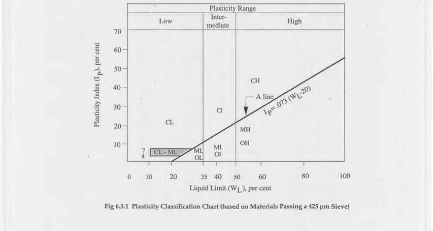 *Fig 6.3.1 Plasticity Classification Chart (based on Materials Passing a 425 μm Sieve)*
**Table 6.3.1 Classification of Soils**
| Classification (for particles smaller than 75 mm and based on estimated weights) | Symbol | Description | % finer than 0.075 mm | Other Criteria |
| :------------------------------------------------------------------------------------------------------------------------------------------- | :----: | :------------------------------------------------------------------------------------ | :-------------------: | :------------------------------------------------------------------------------------------------------------------------------------- |
| Coarse grained soils (over ½ of the material larger than 0.075 mm) — Gravels (over ½ of coarse fraction larger than 4.75 mm) — Clean gravels | GW | Well graded gravels, sandy gravels, sand gravel mixture, little or no fines. | \<5 | $C_u \geq 4$ and $1 \leq C_C \leq 3$ |
| " | GP | Poorly graded gravels, sandy gravels, sand gravel mixture, little or no fines | \<5 | $C_u < 4$ and $1 > C_C > 3$ |
| Gravel with fines | GM | Silty gravels, silty sandy gravels | >12 | $I_p<4$ or the limit values below 'A' line of plasticity chart; for $4>I_p>7$ and limit values above 'A' line, dual symbol required\* |
| " | GC | Clayey gravels, silty clayey gravels | >12 | $I_p>7$ and the limit values above 'A' line of Plasticity Chart |
| Sands (over ½ of coarse fraction smaller than 4.75 mm) — Clean Sands | SW | Well graded sand, gravelly sand, little or no fines | \<5 | $C_u \geq 6$ and $1 \leq C_C \leq 3$ |
| " | SP | Poorly graded sands, gravelly sand, little or no fines | \<5 | $C_u < 6$ and $1 > C_C > 3$ |
| Sands with fines | SM | Silty sand, poorly graded sand silt mixtures | >12 | $I_p<4$ or the limit values below 'A' line of plasticity chart; for $4>I_p>7$ and limit values above 'A' line, dual symbols required\* |
| " | SC | Clayey sand, sand clay mixtures. | >12 | $I_p>7$ and the limit values above 'A' line of plasticity chart |
| Fine grained soils (over ½ of the material smaller than 0.075 mm) — Silts & Clays $w_L < 35$ | ML | Low plastic silt, very fine sands, rock flour, silt with sand | — | Limit values below 'A' line of plasticity chart & $I_p<4$ |
| " | CL | Clays of low plasticity, gravelly clay, sandy clay, silty clay, lean clay | — | Limit values above 'A' line of plasticity chart and/or $I_p>7$ |
| " | OL | Organic silt and clay of low plasticity | — | $\dfrac{\text{Liquid limit (oven dried)}}{\text{Liquid limit (undried)}} < 0.75$ |
| Silts & Clays $3550$ | MH | High plastic silt, micaceous fine sandy or silty soil, elastic silt | — | Limit values on or below 'A' line of plasticity chart |
| " | CH | High plastic clay, fat clay | — | Limit values above 'A' line of plasticity chart |
| " | OH | Organic clay of high plasticity | — | $\dfrac{\text{Liquid limit (oven dried)}}{\text{Liquid limit (undried)}} < 0.75$ |
| Soils of high organic origin | Pt | Peat and highly organic soils | — | Identified by colour, odour, fibrous texture and spongy characteristics |
Note: \* For example, GC-GM, silty, clayey gravel with sand.
$C_u = D_{60}/D_{10}$ = Uniformity Coefficient, $C_C = D_{30}^2/(D_{60} \times D_{10})$ = Coefficient of Curvature
Table 6.3.1's layout in the source (page 6-75) uses merged rows and side-braces to group related classes (e.g. GW/GP under "clean gravels", GM/GC under "gravel with fines") rather than repeating the group label in each row. This has been flattened into a per-row Markdown table, restating the applicable group description in the first data row of each group (marked `"` for repeated groups) to preserve the same information without rowspans, which Markdown tables cannot represent.
**Table 6.3.2 Particle Size Ranges**
| Soil Type | Particle Size Range, mm |
| :------------- | :---------------------: |
| Boulders | >200 |
| Cobbles | 60 - 200 |
| Gravel: Coarse | 20 - 60 |
| Gravel: Medium | 10 - 20 |
| Gravel: Fine | 4.75 - 10 |
| Sand: Coarse | 0.6 - 4.75 |
| Sand: Medium | 0.2 - 0.6 |
| Sand: Fine | 0.075 - 0.2 |
| Silt | 0.002 - 0.075 |
| Clay | \<0.002 |
## 3.5 MATERIALS
All materials for the construction of foundations shall conform to the requirements of Part 5.
### 3.5.1 Concrete
All concrete materials and steel reinforcement used in foundations shall conform to the requirements specified in Chapters 5 and 8 unless otherwise specified in this section.
Concrete to be used in bored or driven cast-in-situ piles shall have a strength greater than 20 MPa and a minimum cement content of 400 kg/m³. For such piles not exceeding a depth of 6 m, where underwater concreting is not involved and where soil conditions are favourable and nonaggressive, the concrete strength may be 15 MPa with a minimum cement content of 350 kg/m³, provided that a higher strength concrete is not needed from structural considerations.
### 3.5.2 Timber
Timber used in foundation shall conform to the standards specified in Sec 2.8 of Part 5. Where timber is exposed to soil or used as load bearing pile above ground water level, it shall be treated in accordance with BDS 819:1975.
## 3.6 TYPES OF FOUNDATION
### 3.6.1 Footings
Footings are foundations that spread the load to the ground at shallow depths. These include individual column footings, continuous wall footings, and combined footings. Footings shall be provided under walls, pilasters, columns, piers, chimneys etc. bearing on soil or rock, except that footings may be omitted under pier or monolithic concrete walls if safe bearing capacity of the soil or rock is not exceeded.
### 3.6.2 Raft Foundation
A foundation consisting of continuous slab that covers the entire area beneath the structure and supports all walls and columns is considered as a raft foundation.
### 3.6.3 Pier Foundation
A cylindrical or prismatic shaft foundation having a ratio of depth to base width greater than 4 is considered a pier foundation. The base of a pier may rest directly on a firm stratum, or on piles. Caisson foundations also fall under the category of pier foundations. A caisson is a hollow shaft or box that is sunk into position and becomes the outer part of finished pier.
### 3.6.4 Pile Foundations
a) **Driven Cast-in-situ Concrete Piles:** A pile formed by driving a steel casing or concrete shell in one or more pieces, which may remain in place after driving or withdrawn, with the inside filled with concrete, falls in this category of piles. Sometimes an enlarged base may be formed by driving out a concrete plug.
b) **Bored Cast-in-situ Concrete Piles:** These are piles formed by concreting bore holes formed by jetting, auguring, rotary drilling or percussion drilling with or without using bentonite mud circulation. Pre-excavation shall be carried out in a manner that will not impair the carrying capacity of the piles already in place or damage adjacent structures. These piles shall be tested for integrity by a suitable method such as dynamic response method and/or load test.
c) **Driven Precast Concrete Piles:** Pile structure capable of being driven into the ground and able to resist handling stresses shall be used for this category of piles.
d) **Under-reamed Concrete Piles:** These are bored cast-in-situ piles having one or more bulbs formed by enlarging the bore hole or pile shaft. Under-reaming should not be done in cohesionless soil both above and below the ground water table.
e) **Timber Piles:** Only structural timber (see Sec 2.8 of Part 5) shall be used as piles for directly transmitting the imposed load to soil. When driven timber poles are used to compact and improve the deposit, this requirement of timber quality may be relaxed.
f) **Other Piles:** Piles such as pipe piles, steel H-piles, bamboo piles, compacted concrete piles (concrete piles with enlarged base in which concrete in the base is placed in small batches that are compacted prior to attaining an initial set), composite piles etc. may be used provided due consideration is given to their installation procedure, durability and load carrying capacity.
## 3.7 GENERAL DESIGN CONSIDERATIONS
### 3.7.1 Design Load and Load Combinations
Foundation design shall consider the following combination of loads.
a) Dead load + normal live load, and
b) Dead load + normal live load + wind load or seismic load whichever is critical.
### 3.7.2 Bearing Pressure
#### 3.7.2.1 Methods for Calculating Bearing Capacity
When physical characteristics such as cohesion, angle of internal friction, density etc. are available, the bearing capacity shall be calculated from stability considerations and shear failure. Established bearing capacity equations shall be used for calculating bearing capacity. The effect of interference of different foundations shall be taken into consideration. A factor of safety of 2.5 shall be adopted to obtain allowable bearing pressure when dead load and normal live load is used. Allowable load shall also limit settlement between supporting elements to a tolerable limit in accordance with Table 6.3.3 and 6.3.4.
**Table 6.3.3 Allowable Displacement Criteria**
| Material | Maximum Deflection between Supports ($L$ = span length) |
| :-------------------------------------------- | :-----------------------------------------------------: |
| Masonry, glass or other frangible material | $L/360$ |
| Metal cladding or similar nonfrangible finish | $L/240$ |
| Steel or concrete frames | $L/150 - L/180$ |
| Wooden frames | $L/100$ |
| Steel or concrete shear walls | As per design |
| Structure | Maximum Slope of Continuous Structure |
| :--------------------------------- | :-----------------------------------: |
| High continuous brick walls | 0.0050-0.0010 |
| Brick dwellings | 0.0030 |
| Brick cladding between columns | 0.0010 |
| Reinforced concrete building frame | 0.0025-0.0040 |
| Reinforced concrete curtain wall | 0.0030 |
| Continuous steel frame | 0.0020 |
| Simply supported steel frame | 0.0050 |
#### 3.7.2.2 Safe Bearing Capacity
For lightly loaded structures (two storeyed or less in occupancy category A, B, C & D) and for preliminary design of any structure, the safe bearing capacities (presumptive bearing values) as given in Table 6.3.5 may be assumed for uniform soil in the absence of test results. Where the bearing material directly under foundation overlie a stratum having smaller presumptive safe bearing capacity, these smaller values shall not be exceeded at the level of such stratum.
#### 3.7.2.3 Field Method of Determining Bearing Capacity
Soil load bearing test such as "Standard Test Method for Bearing Capacity of Soil for Static Load on Spread Footing", (ASTM D1194), shall be performed in lieu of bearing capacity determination by (a) above.
Soil load bearing test shall not be applicable where the proposed bearing stratum is underlain by a stratum of lower strength, unless analysis indicates that the presence of such lower stratum shall not create excessive settlements of the building.
The test shall be made at the levels contemplated for the proposed building footing and at least at two locations within the building premises. The test surface shall be levelled at the elevation of the proposed test for a clear distance of at least 1.5 m all around the test plate. The loaded area shall be square and at least 600 mm x 600 mm. Suitable methods shall be applied to prevent drying of the test surface. In the event ground water is present immediately below, at or above the level required to be tested, dewatering facilities shall be installed to maintain ground water at a minimum of 1.2 m below the level of the test plate during the preparation and duration of the test or tests.
**Table 6.3.4 Rotation Limits for Structures**
| Relative Rotation | Type of Limit and Structure |
| :---------------: | :------------------------------------------------------------------------------------------------------------------------------------------------------------------------------------------------------------ |
| 1/100 | Danger limit for statically determinate structures. |
| 1/150 | Safe limit for statically determinate structures. Danger limit for open steel and reinforced concrete frames, steel storage tanks, and tilt of high, rigid structures. |
| 1/250 | Safe limit for open steel and reinforced concrete frames, steel storage tanks, tilt of high rigid structures. Danger limit for panel walls of framed buildings. Tilting of high buildings may become visible. |
| 1/300 | Limit when difficulties with overhead cranes are to be expected. |
| 1/500 | Safe limit for panel walls of framed buildings. Danger limit for sagging of unreinforced load bearing walls. |
| 1/750 | Limit when difficulties with machinery sensitive to settlement are expected. |
| 1/1000 | Safe limit for sagging of unreinforced load bearing walls. Danger limit for hogging of unreinforced load bearing walls. |
| 1/2000 | Safe limit for hogging of unreinforced load bearing walls. |
**Table 6.3.5 Presumptive Values of Bearing Capacity for Lightly Loaded Structures\***
| Type of Material | Safe Bearing Capacity, kPa |
| :---------------------------------------------------------------------------------------------------------------------------------------------------------------- | :-----------------------------------: |
| 1. Soft Rock or Shale | 440 |
| 2. Gravel, sandy gravel, silty sandy gravel; very dense and offer high resistance to penetration during excavation (soil shall include the groups GW, GP, GM, GC) | 400\*\* |
| 3. Sand (other than fine sand), gravelly sand, silty sand; dry (soil shall include the groups SW, SP, SM, SC) | 200\*\* |
| 4. Fine sand; loose & dry (soil shall include the groups SW, SP) | 100\*\* |
| 5. Silt, clayey silt, clayey sand; dry lumps which can be easily crushed by finger (soil shall include the groups ML, MI, SC, MH) | 150 |
| 6. Clay, sandy clay; can be indented with strong thumb pressure (soil shall include the groups CL, CI, CH) | 150 |
| 7. Soft clay; can be indented with modest thumb pressure (soil shall include the groups CL, CI, CH) | 100 |
| 8. Very soft clay; can be penetrated several centimeters with thumb pressure (soil shall include the groups CL, CI, CH) | 50 |
| 9. Organic clay & Peat (soil shall include the groups OI, OH, OL, Pt) | To be determined after investigation. |
| 10. Fills | To be determined after investigation. |
\* two storeys or less (Occupancy category A, B, C and D)
\*\* 50% of these values shall be used where water table is above the base, or below it within a distance equal to the least dimension of foundation.
#### 3.7.2.4 Allowable Increase
The allowable bearing pressure of the soil determined in accordance with this section may be increased by 33 per cent when lateral forces due to wind or earthquake act simultaneously with gravity loads. No increase in allowable bearing pressure shall be permitted for gravity loads acting alone. In a zone where seismic forces exist, possibility of liquefaction in loose sand, silt and sandy soils shall be investigated.
#### 3.7.2.5 Effect of Dynamic Forces
Where machinery operations or other vibrations are transmitted to the foundation, consideration shall be given in the footing design to prevent detrimental disturbance of the soil.
Impact forces shall be neglected in foundation design except for foundations bearing on loose granular soils; foundations supporting cranes, heavy machinery and similar equipment, or where the ratio of live load causing the impact to the total live plus dead load exceeds 30%.
### 3.7.3 Settlement
#### 3.7.3.1 Estimation of Total Settlement
Total settlement of foundation due to net imposed load shall be estimated in accordance with established engineering principle. An estimate of settlement with respect to the following shall be made where applicable:
i) Elastic compression of the underlying soil below the foundation and of the foundation.
ii) Consolidation including secondary compression of the underlying soil.
iii) Compression and volume change due to change in effective stress or soil migration associated with lowering or movement of ground water.
iv) Seasonal swelling and shrinkage of expansive clays.
v) Ground movement on earth slopes, such as surface erosion, creep or landslide.
vi) Settlement due to adjacent excavation, mining subsidence and underground erosion.
#### 3.7.3.2 Estimation of Differential Settlement
Due consideration shall be given to estimate the differential settlement under the building structure that may arise under the following circumstances:
i) Nonuniformity in subsoil formation within the area covered by the building due to geologic or man-made causes, or anomalies in type, structure, thickness and density of the formation.
ii) Nonuniform pressure distribution due to nonuniform and incomplete loading.
iii) Ground water condition during and after construction.
iv) Loading influence of adjacent structures.
v) Unequal expansion and contraction of soil due to moisture migration, unequal drying, wetting or softening.
#### 3.7.3.3 Allowable Settlement
Allowable or limiting settlement of a building structure will depend on the nature of the structure, the foundation and the soil. As a general rule, a total settlement of 25 mm and a differential settlement of 20 mm between columns in most buildings shall be considered safe for buildings on isolated pad footings. Buildings on raft can usually tolerate greater total settlements. Limiting tolerance for distortion and deflections introduced in a structure is necessarily a subjective process, depending on the status of the building and any specific requirements for serviceability. Where aesthetic criteria dominate, limiting values given in Tables 6.3.3 and 6.3.4 shall be followed as a guide.
## 3.8 REQUIREMENTS FOR FOOTINGS
Design considerations specified in Sec 3.7 shall generally apply for footings. The structural design of reinforced concrete elements shall conform to Chapters 6 and 7 of this Part.
### 3.8.1 Dimension of Footings
Footings shall generally be proportioned from the allowable bearing pressure and stress limitations imposed by limiting settlement.
The angle of spread of the load from the wall base to outer edge of the ground bearing shall not exceed the following:
| Material | Angle of Spread |
| :--------------------- | :------------------------- |
| Brick or stone masonry | ½ horizontal to 1 vertical |
| Lime concrete | ⅔ horizontal to 1 vertical |
| Cement concrete | 1 horizontal to 1 vertical |
A footing shall be placed to depth so that:
a) adequate bearing capacity is achieved,
b) in case of clayey soil, shrinkage and swelling due to seasonal weather change is not significant,
c) it is below possible excavation close by, and
d) it is at least 500 mm below natural ground level unless rock or other weather resistant material is at the surface.
Where footings are to be founded on a slope, the distance of the sloping surface at the base level of the footing measured from the centre of the footing shall not be less than twice the width of the footing.
When adjacent footings are to be placed at different levels, the distance between the edges of footings shall be such as to prevent undesirable overlapping of structures in soil and disturbance of the soil under the higher footing due to excavation of the lower footing.
On a sloping site, footing shall be on a horizontal bearing and stepped. At all changes of levels, footings shall be lapped for a distance of at least equal to the thickness of foundation or three times the height of step, whichever is greater. Adequate precautions shall be taken to prevent tendency for the upper layers of soil to move downhill.
### 3.8.2 Thickness of Footing
The minimum thickness for different types of footing for light structures, shall be as shown in Table 6.3.6.
**Table 6.3.6 Thickness of Footings for Lightly Loaded Structures\***
| Type of Footing | Minimum Thickness | Remark |
| :----------------------------------------------------- | :------------------------------------------------------------- | :------------------------------------------ |
| Masonry | 250 mm; twice the maximum projection from the face of the wall | Greater of the two values shall be selected |
| Plain concrete | 200 mm, or twice the maximum offset in a stepped footing | |
| Reinforced concrete (depth above bottom reinforcement) | 150 mm | Resting on soil |
| Reinforced concrete (depth above bottom reinforcement) | 300 mm | Resting on pile |
\* Two storeys or less in Occupancy category A, B, C and D.
### 3.8.3 Footings on Filled up Ground
Footings shall not be constructed on loosely filled up ground with nonuniform density or consistency, unless adequate strengthening of the soil is made by applying ground improvement techniques.
Where foundations can be separated into two independent units, a slip joint shall be provided to accommodate unequal settlements.
## 3.9 REQUIREMENTS FOR RAFT FOUNDATIONS
Mat or raft and floating foundations shall only be used when the applied load of building or structure is so arranged as to result in practically uniformly balanced loading, and the soil immediately below the mat is of uniform bearing capacity. The characteristics of the soil under the mat or raft shall be considered in the analysis of loading on mats and due allowance shall be made for possible concentrated soil pressures under heavily loaded columns. The structural design of reinforced concrete shall conform to Chapters 6 and 7. The external cover shall conform to Sec 8.1.8 depending on exposure condition.
### 3.9.1 Types of Raft Foundations
A raft foundation may be one of the following types:
a) Flat plate or concrete slab of uniform thickness usually supporting columns spaced uniformly and resting on soils of low compressibility.
b) Flat plates as in (a) but thickened under columns to provide adequate shear and moment resistance.
c) Two way slab and beam system supporting largely spaced columns on compressible soil.
d) Cellular raft or rigid frames consisting of slabs and basement walls, usually used for heavy structures.
### 3.9.2 Design Considerations
Design provisions given in Sec 3.7 shall generally apply. In case the raft supports structure consisting of several parts with varying loads and height, it is advisable to provide separate joints between these parts. Joints shall also be provided wherever there is a change in the direction of the raft. The minimum depth of foundation shall generally be not less than 1.5 m in cohesive soil and 2 m in cohesionless soils. Foundations subject to heavy vibratory loads shall preferably be isolated.
#### 3.9.2.1 Dimensioning
The size and shape of the foundation shall be decided taking into consideration the magnitude of subgrade modulus, the long term deformation of the supporting soil and the distribution of contact pressure.
Distribution of contact pressure underneath a raft is affected by the physical characteristics of the supporting soil. Consideration shall be given to the increased contact pressure developed along the edges of foundation on cohesive soils and the decrease in pressure on granular soils. Both long term and short term deformation and settlement effects shall be considered in the design.
#### 3.9.2.2 Eccentricity
Since raft foundation usually occupies the entire area of a building, it may not be feasible to proportion the raft so that the centroid of the raft coincides with the line of action of the resultant force due to building. In such cases, the effect of eccentricity on the contact pressure distribution shall be considered in the design.
#### 3.9.2.3 Rigidity of Foundation
The rigidity of foundation affects soil pressure distribution which in turn produces additional stresses in the raft due to moments etc. A rigid foundation also generates high secondary stresses. The effects of such rigidity shall be taken into consideration in designing rafts.
#### 3.9.2.4 Methods of Analysis
The essential part of analysis of a raft foundation is the determination of distribution of contact pressure below the mat which is a complex function of the rigidity of raft, and the rigidity of the superstructure and the supporting soil. Any analytical method shall therefore use simplifying assumptions which are reasonably valid for the condition analysed. Choice of a particular method shall therefore be governed by the validity of the assumptions in the particular case.
## 3.10 REQUIREMENTS FOR PIER FOUNDATIONS
Concrete piers shall conform to the requirements for columns. If the bottom of the pier is to be belled for increasing its carrying capacity, such bell shall have at least 300 mm thickness at the edge. The sides shall slope at an angle of not less than 45° with the horizontal. The least permissible dimension shall be 600 mm, irrespective of the pier being circular, square or rectangular.
Plain concrete piers shall not have a height to least lateral dimension ratio more than 6. If this ratio is exceeded, buckling effect shall be taken into consideration. In no case shall the height exceed 12 times the least lateral dimension. The following reduction in allowable concrete stress shall be made when the height exceed 6 times the least lateral dimension unless the least lateral dimension is 1.8 m or greater.
$$
f_r = f_c \left( 1.3 - \frac{H}{20D} \right) \tag{3.10.1}
$$
where
$f_r$ = reduced allowable stress
$f_c$ = allowable stress
$H$ = height of pier, and
$D$ = least lateral dimension of pier
For reinforced concrete piers, the permissible load calculated on the assumption of axially loaded short columns, shall be reduced when the height exceeds 18 times its least lateral dimension by the formula:
$$
P_a = P \left( 1.5 - \frac{H}{36D} \right) \tag{3.10.2}
$$
where
$P_a$ = permissible load,
$H$ = height of pier,
$D$ = least lateral dimension,
$P$ = permissible load as short column.
## 3.11 REQUIREMENTS FOR PILE FOUNDATIONS
A plan showing clearly the designation of all piles by an identifying system shall be filed prior to installation of such piles. All detailed records for individual piles shall bear an identification corresponding to that shown on the plan. A copy of such plan shall be available at the site for inspection at all times during the construction.
The design and installation of pile foundations shall be under the direct supervision of a competent engineer who shall certify that the piles as installed satisfy the design criteria.
Pile foundation shall be designed and installed on the basis of a site investigation report that will include boring or test pits or other subsurface exploration at locations and depths sufficient to determine the position and adequacy of the bearing soil unless adequate data is available upon which the design and installation of the piles can be based. The report shall include but not be limited to:
a) Recommended pile type and capacities,
b) Driving and installation procedure,
c) Field inspection procedure,
d) Pile load test, integrity test requirements,
e) Durability and quality of pile material,
f) Designation of bearing stratum or strata.
All piles shall be braced to provide lateral stability in all directions. Three or more piles connected by a rigid cap shall be considered as being braced, provided that the piles are located in a radial direction from the centroid of the group, not less than 60 degrees apart circumferentially. A two pile group in a rigid cap shall be considered to be braced along the axis connecting the two piles. Piles supporting walls shall be driven alternately in lines at least 300 mm apart and located symmetrically under the centre of gravity of the wall load, unless effective measures are taken to cater for eccentricity and lateral forces, or the wall piles are adequately braced to provide lateral stability.
Piles left in place where a structure has been demolished shall not be used to support new construction unless satisfactory evidence indicates that the piles are sound and meet the requirements of the Code. Such piles shall be load tested or redriven to verify their capacities.
Pile cross-section shall be of sufficient size and strength to withstand driving stresses. Pile diameter/cross-section of a pile shaft at any level shall not be less than the designated nominal diameter/cross-section.
Bored cast-in-situ piles formed by tremie concreting shall have a diameter not less than 400 mm.
### 3.11.1 Design Considerations
#### 3.11.1.1 Bearing Capacity/Allowable Load/Safe Load
The allowable axial load and lateral loads on piles shall be determined by an established method of analysis or load test.
The allowable axial load on a pile shall be the least value permitted by consideration of the following factors:
i) The capacity of the pile as a structural member.
ii) The allowable bearing pressure on soil strata underlying the pile tip.
iii) The resistance to penetration of the pile, including resistance to driving, resistance to jacking, the rate of penetration, or other equivalent criteria.
iv) The capacity as indicated by load test, where load tests are required.
#### 3.11.1.2 Use of Static Formula
The ultimate load carrying capacity of a pile may be calculated from soil properties. The soil properties needed are shear strength parameters (cohesion, angle of internal friction), and soil density.
Any static formula used shall consider appropriate value of adhesion factor (α) for cohesive soil or coefficient of horizontal soil stress ($k_s$) that is consistent with soil condition and pile installation procedure for estimating frictional resistance of an individual pile. In estimating tip resistance, account shall be taken of the change in soil condition at pile tip due to installation process.
The minimum factor of safety on capacity calculated on the basis of static formula shall be 2.5. The factor of safety shall actually depend on the reliability of the formula, depending on a particular site and locality and the reliability of the subsoil parameters employed in the calculations. The assumption of a factor of safety shall also consider the load settlement characteristics of the structure as a whole on a given site.
#### 3.11.1.3 Dynamic Formula
Dynamic formula may be used for driven piles in cohesionless soils such as gravels, coarse sand and such deposits where pore pressure developed due to driving is quickly dissipated.
The allowable compressive load on any pile when determined by the application of an established empirical formula shall not exceed 400 kN. The formula load shall be determined for gravity or power actuated hammers, and hammer energy used shall be the maximum consistent with size, strength and weight of the driven piles. The use of a follower shall be permitted only when approved. The introduction of fresh hammer cushion or pile cushion material prior to final penetration shall not be permitted. Wave equation analysis method may be used for estimating pile capacity of driven piles.
#### 3.11.1.4 Load Test Results
Where more accurate estimate of load carrying capacity of a pile is required, tests in accordance with "Standard Test Method for Piles Under Static Compressive Load", (ASTM D1143) or equivalent shall be performed on individual piles. At least one pile shall be tested in each area of uniform subsoil condition. Where necessary, additional piles shall be load tested to establish the safe design capacity. The resulting allowable loads shall not be more than one-half of that test load which produces a permanent net settlement of not more than 0.00028 mm/kg of test load nor 20 mm.
#### 3.11.1.5 Negative Skin Friction
Piles installed in compressible fill or soft soil subject to compression shall be designed against additional downward load due to downdrag, generally known as negative skin friction of the compressible soil.
In estimating negative skin friction the following factors shall be considered:
i) Relative movement between soil and pile shaft.
ii) Relative movement between any underlying compressible soil and pile shaft.
iii) Elastic compression of the pile under the working load.
iv) The rate of consolidation of the compressible layer.
Negative skin friction is mobilized only when tendency for relative movement between pile shaft and surrounding soil exists.
#### 3.11.1.6 Structural Capacity
Piles shall have the necessary structural capacity to resist all handling stresses during driving or installation and the necessary strength to transmit the load imposed on them to soil.
#### 3.11.1.7 Axial Capacity
The axial carrying capacity of a pile fully embedded in soil with undrained shear strength greater than 10 kN/m² shall not be limited by its strength as long column. If the soil is weak (undrained shear strength less than 10 kN/m²), consideration shall be given to determine whether the shaft would behave as a long column. If necessary, suitable reductions shall be made in its structural strength considering buckling. The effective length of a pile not secured against buckling by adequate bracing shall be governed by the conditions imposed on it by the structure it supports and by the nature of the soil in which it is installed.
#### 3.11.1.8 Lateral Capacity
Lateral capacity of vertical single piles shall be the least of the values calculated on the basis of soil failure, structural capacity of the pile and deflection of the pile head.
Deflection calculations require horizontal subgrade modulus of the surrounding soil. When considering lateral load on piles, the effect of other coexistent loads, including axial load on the pile, shall be taken into consideration for checking structural capacity of the shaft.
For estimating the depth of fixity, established method of analysis shall be used, or lateral load test to at least twice the proposed design working load shall be made. The resulting allowable load shall not be more than one-half of that test load which produces a gross lateral movement of 25 mm at the ground surface.
All piles standing unbraced in air, water or soils not capable of providing lateral support shall be designed as columns in accordance with the provisions of this Code.
#### 3.11.1.9 Spacing of Piles
The centre to centre spacing of piles shall be considered from practical aspects of installing the piles and from the nature of load transfer to the soil and possible reduction in bearing capacity of a group of piles. The spacing of piles shall be such that the average load on the bearing strata will not exceed the safe bearing value of those strata as determined by test boring or other established methods.
Where piles are founded on a very hard stratum and their capacity is mainly derived from end bearing, the spacing shall be governed by the capacity of the end bearing strata. The minimum spacing in such cases shall be 2.5 times the diameter of the pile shaft.
Piles deriving their capacity from frictional resistance shall be sufficiently apart to ensure that the zones of soil from which the piles derive their support do not overlap to such an extent that their bearing values are reduced. Generally, in such cases, the spacing shall not be less than 3.0 times the diameter of the shaft.
In cases of loose sand filling, where displacement during piling may be absorbed by vertical and horizontal compaction of the strata, the minimum spacing may be 2.0 times the diameter of the shaft. For noncircular pile sections, the diameter of the circumscribing circle shall be considered as diameter of the pile shaft.
#### 3.11.1.10 Batter Piles
Batter piles shall be used to transfer inclined load and horizontal forces. In the preliminary design, the load on a batter pile is generally considered to be axial. The distribution of load between batter and vertical piles in a group may be determined graphically or by analytical methods. Due care shall be given to secondary bending as a result of pile cap movement, particularly when the cap is rigid.
Free standing batter piles are subject to bending moments due to their own weight, or external forces from other sources. Batter piles in loose fill or consolidating deposits may become laterally loaded due to settlement of the surrounding soil. In consolidating clay, special precautions, like provision of permanent casing, shall be taken.
#### 3.11.1.11 Factor of Safety
A factor of safety shall be applied to all estimates of failure load after considering:
i) the reliability of the value of the ultimate bearing capacity,
ii) the type of superstructure and type of loading, and
iii) allowable total and differential settlement of the structure.
When ultimate bearing capacity is calculated from either static formula or dynamic formula, the above factors shall be considered. The minimum factor of safety on static formula shall be 2.5.
When safe load on a pile is assessed by applying a factor of safety to load test data, the safety factor shall be increased in unfavourable conditions where:
i) settlement is to be limited or differential settlement avoided (i.e. for accurately aligned machinery or a fragile finish of superstructure),
ii) large impact or vibrating loads are expected,
iii) soil strength or modulus may be expected to deteriorate with time,
iv) live load on a structure carried by friction piles is a considerable portion of the total load and approximate the dead load in duration.
#### 3.11.1.12 Transient Loading/Overloading
The maximum permissible increase over the safe load of a pile due to wind load is 25 per cent. In the case of loads and moments arising due to earthquakes, an increase of 25 to 50 per cent may be allowed depending on soil type except for poorly graded sands with N values less than 10. In case of submerged loose sands, vibration caused by earthquake may cause liquefaction or excessive total and differential settlements. This aspect of the problem shall be investigated and appropriate methods of improvements adopted to achieve suitable values of N. Alternatively, pile foundation shall be provided and taken to depths well into the layers which are not likely to liquefy.
Where a pile in a group, designed for a certain safe load, is found during or after installation, to fall just short of the load required to be carried by it, an overload of up to 10% of the pile capacity may be allowed on each pile. The total overloading on the group shall not be more than 10 per cent of the capacity of the group nor more than 40 per cent of the allowable load on a single pile.
#### 3.11.1.13 Reinforcement
Depending on the design, installation conditions and the loading condition, the amount of reinforcement and its arrangement shall vary. Reinforcements shall be placed to provide at least 75 mm of clear cover, measured to the surface of the pile cap that is in contact with the ground. All reinforcements adjacent to timber or concrete piling shall have a minimum of 25 mm of concrete protection. Reinforcements shall extend to within 100 mm of the edge of the pile cap.
For precast concrete piles, for a length equal to at least three times the minimum lateral dimension at each end of the pile, lateral tie reinforcement consisting of 6 mm diameter bar or larger shall be placed at a spacing not more than 75 mm centre to centre, or an equivalent spiral shall be provided. Elsewhere, the spacing of the ties or the pitch of the spiral may be increased to 300 mm. The minimum amount of longitudinal reinforcement shall be one and a half per cent of the concrete section, placed in a symmetrical pattern of at least 4 bars. If prestressed piles are used, the minimum residual compression in the pile section shall be 4800 kN/m². The cover of concrete over all the reinforcements, including ties, shall not be less than 50 mm. However, where piles are exposed to sea water or water having other corrosive content, the cover shall nowhere be less than 70 mm. Cover shall be measured clear from the main or longitudinal reinforcement.
In cast-in-situ piles, except for steel dowels embedded 1500 mm or less in pile, reinforcement, where required, shall be assembled and tied together and shall be placed in the pile as a unit before the reinforced portion of the pile is filled with concrete. Minimum vertical reinforcement in bored cast-in-situ piles shall be four 13 mm bars and embedded at least half the length of the pile.
For piles installed with a hollow stem auger, where longitudinal steel reinforcement is placed without lateral ties, the reinforcement shall be placed through ducts in the auger prior to filling the pile with concrete. All pile reinforcements shall have a concrete cover of not less than 65 mm.
In under-reamed bored cast-in-situ piles, the minimum area of longitudinal reinforcement in stem shall be 0.4 per cent. Reinforcement is to be provided in the full length, and a minimum of 3 bars of 10 mm of diameter mild steel or 3 bars of 8 mm diameter high strength steel shall be used. Transverse reinforcement shall be provided with bars not less than 6 mm in diameter and at a spacing not more than the stem diameter or 300 mm, whichever is less. Under-reaming shall not be done in cohesionless soil both above and below ground water table. The minimum depth of under-reaming bulb shall be either 2.75 m or below the level of stabilized moisture content, whichever is deeper.
In under-reamed compaction piles, a minimum of four 12 mm bars shall be provided. For piles of length exceeding 5 m and diameter exceeding 375 mm, a minimum of six 12 mm ø bars shall be provided. The circular stirrups of such piles shall be provided with a minimum of 8 mm ø bars. For piles exceeding 400 mm in diameter, a minimum of six 12 mm ø bars shall be provided.
#### 3.11.1.14 Integrity
Piles shall be installed in such a manner and sequence as to prevent distortion or damage to piles being installed or already in place, to the extent that such distortion or damage affects the structural integrity of the piles.
### 3.11.2 Design of Pile Caps
Pile caps shall be of reinforced concrete. The soil immediately below the pile cap shall not be considered as carrying any vertical load. The tops of all piles shall be embedded not less than 75 mm into pile caps and the cap shall extend at least 100 mm beyond the edge of all piles. The tops of all piles shall be cut back to sound material before capping.
The pile cap shall be rigid enough, so that the imposed load can be distributed on the piles in a group equitably.
The cap shall generally be cast over a 75 mm thick levelling course of concrete. The clear cover for the main reinforcement in the cap slab under such condition shall not be less than 60 mm.
### 3.11.3 Installation Procedure
In cast-in-situ bored piles, concrete shall be placed only after excavation has been completed, inspected and accepted, and steel reinforcement accurately placed and adequately secured. Concrete shall be placed in one continuous operation in such a manner as to ensure the exclusion of any foreign matter and to secure a full sized shaft. Concrete shall not be placed through water except where tremie methods are approved. When depositing concrete from the top of pile, the concrete shall not be chuted directly into the pile but shall be poured in a rapid and continuous operation through a funnel hopper centred at the top of the pile.
In tremie concreting, toe of the tremie shall be set at a maximum of 150 mm above the bottom of the borehole. Maximum permissible siltation in bore hole prior to start of concrete operation shall be 75 mm.
For drilled or augered uncased concrete piles, if pile shafts are formed through unstable soil and concrete is placed in an open drill hole, a steel liner shall be inserted in the hole prior to placing concrete. If the steel liner is withdrawn during concreting, the level of concrete shall be maintained above the bottom of the liner to a sufficient height to offset any hydrostatic or lateral earth pressure.
If concrete is placed by pumping through a hollow stem auger, the auger shall not be permitted to rotate during withdrawal and shall be withdrawn in a steady continuous motion. Concrete pumping pressures shall be measured and shall be maintained high enough at all times to offset hydrostatic and lateral earth pressure. Concrete volumes shall be measured to ensure that the volume of concrete placed in each pile is equal to or greater than the theoretical volume of the hole created by the auger. If the installation process of any pile is interrupted or a loss of concreting pressure occurs, the hole shall be redrilled to original depth and reformed.
Augured cast-in-situ pile shall not be installed within 6 pile diameters centre to centre of a pile filled with concrete less than 24 hours old. If concrete level in any bored pile drops, the pile shall be rejected and replaced. Bored cast-in-situ concrete piles shall not be drilled/bored within a clear distance of 3 m from an adjacent pile with concrete less than 48 hours old.
Precast concrete piles shall not be driven within 6 pile diameters centre to centre in granular soil or within one-half the pile length in cohesive soils of a pile filled with concrete less than 48 hours old unless approved by the designer. If the concrete surface in a completed pile rises or drops, the pile shall be rejected and replaced. Piles shall not be installed in soils which could cause pile heave.
In enlarged base piles, enlarged bases are formed in or driven into granular soils either by compacting concrete or driving a precast base. All piles shall be constructed in the same manner as successful prototype test piles were driven for the project. Pile shafts extending through peat or other organic soil shall be encased in a permanent steel casing. If a cased shaft is used, it shall be adequately reinforced to resist column action or the annular space around the pile shaft shall be filled sufficiently to re-establish the lateral support of the soil. If pile heave occurs, the pile shall be rejected unless it can be demonstrated that the pile is not damaged and capable of carrying twice its design load.
Steel cased piles shall have the steel shell mandrel driven their full length in contact with surrounding soil, left permanently in place and filled with concrete. No pile shall be driven within 4.5 times the average pile diameter of a pile filled with concrete less than 24 hours old. Concrete shall not be placed in steel shells within the heave range of driving.
A precast concrete pile shall not be driven before the concrete has attained a compressive strength of at least 0.75 $f_c'$ except that in all cases the concrete strength shall be sufficient to withstand handling and driving forces. All piles shall be handled and driven so as not to cause injury or overstressing which may affect their durability or strength.
A prestressed pile shall not be driven before the concrete has attained a compressive strength of at least 28 kN/m², but not less than such strength sufficient to withstand handling and driving forces.
### 3.11.4 Pile Concreting
#### 3.11.4.1
For bored or driven cast-in-situ piles, concrete shall be deposited in such a way as to preclude segregation. Concrete shall be placed continuously until it is brought to the required level. The top surface shall be maintained as level as possible and the formation of seams shall be avoided.
#### 3.11.4.2
For under-reamed piles, the slump of concrete shall range between 100 mm and 150 mm for concreting in water free holes.
#### 3.11.4.3
For large diameter holes concrete may be placed by tremie or by drop bottom bucket; for small diameter boreholes a tremie shall be utilized.
A slump of 125 mm to 150 mm shall be maintained for concreting by tremie. In case of tremie concreting, for piles of smaller diameter and length up to 10 m, the minimum cement content shall be 350 kg/m³ of concrete. For larger diameter and/or deeper piles, the minimum cement content shall be 400 kg/m³ of concrete (see also Sec 3.5.1).
#### 3.11.4.4
For concreting under water, the concrete shall contain at least 10 per cent more cement than that required for the same mix placed in the dry. The amount of coarse aggregate shall be not less than one and a half times, nor more than two times, that of the fine aggregate. The materials shall be so proportioned as to produce a concrete having a slump of not less than 100 mm, nor more than 150 mm, except where plasticizing admixtures is used in which case, the slump may be 175 mm.
The source (page 6-86) numbers two consecutive clauses "3.11.4.3" (one introducing tremie/drop-bottom placement, the next specifying the tremie slump and cement content). This is a duplicate section number in the original gazette text, not an extraction artifact; it has been preserved by merging the second "3.11.4.3" clause's text into the same subsection body rather than inventing a "3.11.4.5" number not present in the source.
### 3.11.5 Load Test Arrangement and Instrumentation
The ultimate load carrying capacity of a single pile may be determined with reasonable accuracy from load testing. The load test on a pile shall not be carried out earlier than four weeks from the date of casting the pile. A minimum of one pile at each project shall be load tested for bored cast-in-situ piles.
Two principal types of test may be used for applying loading on piles - the constant rate of penetration (CRP) and the maintained load (ML) test. The CRP method is essentially a test to determine the ultimate load on a pile and is therefore applied only to preliminary test piles or research type investigations. In this test the compressive force is progressively increased to cause the pile to penetrate the soil at constant rate until failure occurs. In the ML test the load is increased in stages to 1.5 times or twice the working load with time settlement curve recorded at each stage of loading and unloading. The ML test may also be taken to failure by progressively increasing the load in stages.
In CRP test the recommended rates of penetration are 0.75 mm/min for friction piles in clay and 1.55 mm/min for piles end bearing in granular soil. The CRP test shall not be used for checking compliance with specification requirements for the maximum settlement at given stages of loading.
In the ML test, the load test procedure as specified in "Standard Test Method for Piles Under Static Axial Compressive Load", (ASTM D1143), shall be followed.
Uplift or tension test on piles subject to tension/uplift shall be performed by a continuous rate of uplift (CRU) or an incremental loading (i.e. ML) test. Where uplift loads are intermittent or cyclic in character, as in wave loading on a marine structure, it is recommended to adopt repetitive loading on the test pile. The tests shall be performed in accordance with "Standard Test Method for Individual Piles Under Static Axial Tensile Load", (ASTM D3689).
Lateral load tests shall be performed in accordance with "Standard Test Method for Piles Under Lateral Loads", (ASTM D3966).
## 3.12 EXCAVATION AND FILLS
Excavation for building foundation or for other purposes shall be done in a safe manner so that no danger to life and property prevails at any stage of the work or after completion. The requirements of this section shall be satisfied for all such works in addition to those of Sec 3.2 of Part 7.
Permanent excavations shall have retaining walls of sufficient strength made of steel, masonry, or reinforced concrete to retain the embankment, together with any surcharge load.
Excavations for any purpose shall not extend within 300 mm under any footing or foundation, unless such footing or foundation is first properly underpinned or protected against settlement.
### 3.12.1 Support to Adjoining Buildings and Structures
#### 3.12.1.1 Notice to Adjoining Property
Prior to any excavation close to an adjoining building in another property, a written notice shall be given to the owner of the adjoining property at least 10 days ahead of the date of excavation. The person undertaking the excavation shall, where necessary, incorporate adequate provisions and precautionary measures to ensure safety of the adjoining property and shall supply the details of such measures in the notice to the owner of the adjoining property. He shall obtain approval of the Authority regarding the protective provisions, and permission of the owner of the adjoining property regarding the proposed excavation, in writing.
The protective measures shall incorporate the following:
a) Where the level of the foundations of the adjoining structure is at or above the level of the bottom of the proposed excavation, the vertical load of the adjoining structure shall be supported by proper foundations, underpinning, or other equivalent means.
b) Where the level of the foundations of the adjoining structure is below the level of the bottom of the proposed excavation, provision shall be made to support any increased vertical or lateral load on the existing adjoining structure caused by the new construction.
If on giving the required notice, incorporating or proposing to incorporate the protective provisions which have duly been approved by the Authority, the owner of the adjoining property refuses to permit the proposed excavation or to allow necessary access and other facilities to the person undertaking the excavation for providing the necessary and approved protection to the adjoining property, the responsibility for any damage to the adjoining property due to the excavation shall be that of the owner of the adjoining property.
#### 3.12.1.2 Excavation Work
Every excavation shall be provided with safe means of ingress and exit kept available at all times. When an excavation has been completed, or partly completed and discontinued, abandoned or interrupted, or the required permits have expired, the lot shall be filled and graded to eliminate all steep slopes, holes, obstructions or similar sources of hazard. Fill material shall consist of clean, noncombustible substances. The final surface shall be graded in such a manner as to drain the lot, eliminate pockets, prevent accumulation of water, and preclude any threat of damage to the foundations on the premises or on the adjoining property.
#### 3.12.1.3 Methods of Protection
a) **Shoring, Bracing and Sheeting:** With the exception of rock cuts, the sides of all excavations, including related or resulting embankments, 1.5 m or greater in depth or height measured from the level of the adjacent ground surface to the deepest point of excavation, shall be protected and maintained by shoring, bracing, and sheeting, sheet piling, or other retaining structures. Alternatively, excavated slopes may be inclined not steeper than 1:1, or stepped so that the average slope is not steeper than forty five degrees, with no step more than 1.5 m high, provided such slope does not endanger any structure, including subsurface structures. All sides or slopes of excavations or embankments shall be inspected after rainstorms, or any other hazard increasing event, and safe conditions shall be restored. Sheet piling and bracing needed in trench excavations shall have adequate strength to resist the possible forces resulting from earth or surcharge pressure.
b) **Guard Rail:** A guard rail or a solid enclosure at least 1 m high shall be provided along the open sides of excavations, except that such guard rail or solid enclosure may be omitted from a side or sides when access to the adjoining area is precluded, or where side slopes are one vertical to three horizontal or flatter.
c) **Placing of Construction Material:** Excavated materials and superimposed loads such as equipment, trucks, etc. shall not be placed closer to the edge of the excavation than a distance equal to one and one-half times the depth of such excavation, unless the excavation is in rock or the sides have been sloped or sheet piled (or sheeted) and shored to withstand the lateral force imposed by such superimposed load. When sheet piling is used, it shall extend at least 150 mm above the natural level of the ground. In the case of open excavations with side slopes, the edge of excavation shall be taken as the toe of the slope.
### 3.12.2 Safety Regulations
Whenever subsurface operations are conducted that may impose loads or movement on adjoining property, such as driving of piles, dewatering of soils, or soil densification, the effects of such operations on adjoining property and structures shall be considered. The owner of the property that may be affected shall be given 48 hours written notice of the intention to perform such operations. Where construction operations will cause changes in the ground water level under adjacent buildings, the effects of such changes on the stability and settlement of the adjacent foundation shall be investigated and provision made to prevent damage to such buildings. When a potential hazard exists, elevations of the adjacent buildings shall be recorded at intervals of twenty four hours or less to ascertain if movement has occurred. If so, necessary remedial action shall be undertaken immediately.
Whenever an excavation or fill is to be made that will affect safety, stability, or usability of adjoining properties or buildings, the adjoining properties or buildings shall be protected as required by the provisions of Sec 3.12.1.
On excavation, the soil material directly underlying footings, piers, and walls shall be inspected by an engineer/architect prior to construction of the footing. If such inspection indicates that the soil conditions do not conform to those assumed for the purposes of design and described on the plans, or are unsatisfactory due to disturbance, then additional excavation, reduction in allowable bearing pressure, or other remedial measures shall be adopted.
Except in cases where a proposed excavation will extend less than 1.5 m below grade, all underpinning operations and the construction and excavation of temporary or permanent cofferdams, caissons, bracing, excavation surfaces, or other constructions or excavations required for or affecting the support of adjacent properties or buildings shall be subject to controlled inspection. The details of underpinning, and construction of cofferdams, caissons, bracing or other constructions required for the support of adjacent properties or buildings shall be shown on the plans or prepared in the form of shop or detail drawings and shall be approved by the engineer who prepared the plans.
### 3.12.3 Slope Stability and Protection
The possibility of overturning and sliding of the building shall be considered. The minimum factor of safety against overturning of the structure as a whole shall be 1.5. Resistance against overturning shall be provided by the dead load of the building, the allowable uplift capacity of piling, anchors, weight of the soil directly overlying footings provided that such soil cannot be excavated without recourse to major modification of the building, or by any combination of these factors.
The minimum factor of safety against sliding of the structure under lateral load shall be 1.5. Resistance to lateral loads shall be provided by friction between the foundation and the underlying soil, passive earth pressure, batter piles or by plumb piles, subject to the following:
i) The resistance to lateral loads due to passive earth pressure shall not be taken into consideration where the abutting soil could be removed inadvertently by excavation.
ii) In case of pile supported structures, frictional resistance between the foundation and the underlying soil shall be discounted.
iii) The available resistance to friction between the foundation and the underlying soil shall be predicted on an assumed friction factor of 0.5. A greater value of the coefficient of friction may be used subject to verification by analysis and test.
The faces of cut and fill slopes shall be prepared and maintained to control erosion. The control may consist of effective planting. The protection for slopes shall be installed as soon as practicable. Where cut slopes are not subject to erosion due to erosion resistant character of the materials, such protection may be omitted.
Where necessary, check dams, cribbing, riprap or other devices or methods shall be employed to control erosion.
### 3.12.4 Dewatering and Ground Water Control
All excavations shall be drained and the drainage maintained as long as the excavation continues or remains. Where necessary, pumping shall be used. No condition shall be created as a result of construction operations that will interfere with natural surface drainage. Water courses, drainage ditches, etc. shall not be obstructed by refuse, waste building materials, earth, stones, tree stumps, branches, or other debris that may interfere with surface drainage or cause the impoundment of surface water.
### 3.12.5 Quality of Fill
The excavation outside the foundation shall be backfilled with soil that is free of organic material, construction debris and large rocks. The backfill shall be placed in lifts and compacted in a manner which does not damage foundation, the waterproofing or damp-proofing material.
#### 3.12.5.1 Placement of Fill to Support Building
Fills to be used to support the foundation of any building or structure shall be placed in accordance with established engineering principle. Before placement of the fill, the existing ground surface shall be stripped off all organic growth, timber, rubbish and debris. After stripping, the ground surface shall be compacted. Materials for fill shall consist of sand, gravel, crushed stone, crushed earth, or a mixture of these. The fill material shall contain no particles exceeding 100 mm in the largest dimension. A soil investigation report and a report of satisfactory placement of fill, both acceptable to the Building Official shall be submitted. In an uncontrolled fill, the soil within the building area shall be explored using test pits. At least one test pit penetrating at least 2 m below the level of the bottom of the proposed foundation shall be provided for every 200 m² of building area. Wherever such test pits consistently indicate that the fill is composed of material that is free of voids and free of extensive inclusion of mud, organic materials such as paper, garbage, cans, metallic refuse or debris, the fill material shall be acceptable. Where the fill shows voids or inclusions as described above, either the fill shall be treated as having no presumptive bearing capacity, or the building shall incorporate adequate strength and stiffness to bridge such voids or inclusions or shall be articulated to prevent damage due to differential or localized settlement of the fill.
#### 3.12.5.2 Specification of Density and Water Content
Where foundations are to be placed on controlled fill materials, the fill must be compacted in layers not exceeding 300 mm. Clear specification shall be provided for the range of water content, the degree of compaction to be achieved and the method of compaction that shall be followed. Such specification shall be based on the shear strength requirement for the fill soil and allowable settlement estimate. The minimum density of controlled fill shall be 95% of the optimum density obtained from "Standard Test Method for Moisture-Density Relation of Soil and Soil-Aggregate Mixture using 10-lb (4.54 kg) Rammer and 18-in (457 mm) Drop", (ASTM D1557).
The degree of compaction achieved in a fill shall be obtained from insitu density measurements. No new layer shall be placed unless a satisfactory density is attained in each layer.
## 3.13 WATERPROOFING AND DAMP-PROOFING
Walls or portions thereof that retain earth and enclose interior spaces, and floors below grade shall be waterproofed and damp-proofed, with the exception of those spaces where such omission is not detrimental to the building or occupancy. The roof is also required to be waterproofed. The owner shall perform a subsurface investigation to determine the possibility of the ground water table rising above the proposed elevation of the floor or floors below grade unless satisfactory data from adjacent areas demonstrate that ground water has not been a problem.
There may arise two situations: (i) where no hydrostatic pressure occurs and (ii) where hydrostatic pressure occurs. Where hydrostatic pressure conditions exist, floors and walls below finished ground level shall be waterproofed in accordance with Sec 3.13.1 below. Where hydrostatic pressure conditions do not exist, damp-proofing and perimeter drainage shall be provided in accordance with Sec 3.13.2 below. In addition, the damp-proofing and waterproofing shall also meet the requirements of Sec 3.13.3. All damp-proofing and waterproofing materials shall conform to the requirements of Sec 2.16.7 of Part 5.
### 3.13.1 Waterproofing where Hydrostatic Pressure Occurs
Where ground water investigation indicates that a hydrostatic pressure condition exists, or is likely to occur, walls and floors shall be waterproofed in accordance with this section.
#### 3.13.1.1 Floor Waterproofing
Floors required to be waterproofed shall be of concrete and shall be designed and constructed to withstand the anticipated hydrostatic pressure.
Waterproofing of the floor shall be accomplished by placing under the slab a membrane of rubberized asphalt, or butyl rubber, or a modified asphalt, or neoprene, or not less than 0.15 mm polyvinyl chloride or polyethylene, or other approved materials, capable of bridging nonstructural cracks. Joints in the membrane shall be lapped not less than 150 mm and sealed in an approved manner.
#### 3.13.1.2 Wall Waterproofing
Walls required to be waterproofed shall be of concrete or masonry designed to withstand the anticipated hydrostatic pressure and other lateral loads. Prior to the application of waterproofing materials on concrete walls, all holes and recesses resulting from the removal of form ties shall be sealed with a bituminous material or other approved methods or materials. Unit masonry walls shall be pargeted on the exterior surface below ground level with not less than 10 mm of Portland cement mortar. The pargeting shall be continued to the foundation. Pargeting of unit masonry walls is not required where a material is approved for direct application to the masonry.
Waterproofing shall be applied from a point 300 mm above the maximum elevation of the ground water table down to the top of the spread portion of the foundation. The remainder of the wall up to a level not less than 150 mm above finished grade shall be damp-proofed in accordance with Sec 3.13.2.2.
Wall waterproofing materials shall consist of two-ply hot-mopped felts, not less than 0.15 mm polyvinyl chloride, 1.0 mm polymer modified asphalt, 0.15 mm polyethylene or other approved methods or materials capable of bridging nonstructural cracks. Joints in the membrane shall be lapped not less than 150 mm and sealed in an approved manner.
Joints in walls and floors, joints between the wall and the floor, and penetrations of the wall and floor shall be made watertight utilizing established methods and materials.
### 3.13.2 Damp-proofing with no Hydrostatic Pressure
Where hydrostatic pressure will not occur, floors and walls shall be damp-proofed and a subsoil drainage system shall be installed as described below:
#### 3.13.2.1 Floor Damp-proofing
For floors, damp-proofing materials shall be installed between the floor and base materials. The base material shall not be less than 100 mm in thickness consisting of gravel or crushed stone containing not more than 10 per cent material that passes a 4.76 mm sieve. Where a site is located in well drained gravel or sand/gravel mixture, a floor base is not required. When the finished ground level is below the floor level for more than 25 per cent of the perimeter of the building, the base material need not be provided. Where a separate floor is provided above a concrete slab the damp-proofing may be installed on top of the slab.
Damp-proofing materials, where installed beneath the slab, shall consist of not less than 0.15 mm polyethylene with joints lapped not less than 150 mm, or other approved methods or materials. Where permitted to be installed on top of the slab, damp-proofing shall consist of mopped on bitumen, not less than 0.1 mm even, or other approved methods or materials. Joints in membranes shall be lapped not less than 150 mm and sealed in an approved manner.
#### 3.13.2.2 Wall Damp-proofing
For walls, damp-proofing materials shall be installed on the exterior surface and shall extend from a point 150 mm above grade, down to the top of the spread portion of the foundation.
Wall damp-proofing material shall consist of a bituminous material, acrylic modified cement base coating, rubberized asphalt, polymer-modified asphalt, butyl rubber, or other approved materials capable of bridging nonstructural cracks.
#### 3.13.2.3 Perimeter Drain
A drain shall be provided around the perimeter of a foundation that consists of gravel or crushed stone containing not more than 10 per cent material that passes through a 4.76 mm sieve. The drain shall extend a minimum of 300 mm beyond the outside edge of the foundation. The thickness shall be such that the bottom of the drain is not higher than the bottom of the base under the floor, and that the top of the drain is not less than 150 mm above the base of the foundation. The top of the drain shall be covered with an approved filter membrane material. Where a drain tile or perforated pipe is used, the invert of the pipe or tile shall not be higher than the floor elevation. The top of joints or the top of perforations shall be protected with an approved filter membrane material. The pipe or tile shall be placed on not less than 50 mm of gravel or crushed stone complying with this section, and shall be covered with not less than 150 mm of the same material.
The floor base and foundation perimeter drain shall discharge by gravity or mechanical means into an approved drainage system. Where a site is located in well drained gravel or sand/gravel mixture, a dedicated drainage system is not required. When the finished ground level is below the floor level for more than 25 per cent of the perimeter of the building, the foundation drain need be provided only around that portion of the building where the ground level is above the floor level.
### 3.13.3 Other Damp-proofing and Waterproofing Requirements
#### 3.13.3.1 Placement of Backfill
The excavation outside the foundation shall be backfilled with soil that is free of organic material, construction debris and large rocks. The backfill shall be placed in lifts and compacted in a manner which does not damage the waterproofing or damp-proofing material or structurally damage the wall.
#### 3.13.3.2 Site Grading
The ground immediately adjacent to the foundation shall be sloped away from the building at a slope not less than 1 unit vertical in 12 units horizontal (1:12) for a minimum distance of 2.5 m measured perpendicular to the face of the wall or an alternative method of diverting water away from the foundation shall be used. Consideration shall be given to possible additional settlement of the backfill when establishing the final ground level adjacent to the foundation.
#### 3.13.3.3 Erosion Protection
Where water impacts the ground from the edge of the roof, down spout, scupper, valley or other rainwater collection or diversion device, provisions shall be used to prevent soil erosion and direct the water away from the foundation.
## Related Appendix
Appendix B Methods of Soil Exploration and Sampling
*Fig 6.3.1 Plasticity Classification Chart (based on Materials Passing a 425 μm Sieve)*
**Table 6.3.1 Classification of Soils**
| Classification (for particles smaller than 75 mm and based on estimated weights) | Symbol | Description | % finer than 0.075 mm | Other Criteria |
| :------------------------------------------------------------------------------------------------------------------------------------------- | :----: | :------------------------------------------------------------------------------------ | :-------------------: | :------------------------------------------------------------------------------------------------------------------------------------- |
| Coarse grained soils (over ½ of the material larger than 0.075 mm) — Gravels (over ½ of coarse fraction larger than 4.75 mm) — Clean gravels | GW | Well graded gravels, sandy gravels, sand gravel mixture, little or no fines. | \<5 | $C_u \geq 4$ and $1 \leq C_C \leq 3$ |
| " | GP | Poorly graded gravels, sandy gravels, sand gravel mixture, little or no fines | \<5 | $C_u < 4$ and $1 > C_C > 3$ |
| Gravel with fines | GM | Silty gravels, silty sandy gravels | >12 | $I_p<4$ or the limit values below 'A' line of plasticity chart; for $4>I_p>7$ and limit values above 'A' line, dual symbol required\* |
| " | GC | Clayey gravels, silty clayey gravels | >12 | $I_p>7$ and the limit values above 'A' line of Plasticity Chart |
| Sands (over ½ of coarse fraction smaller than 4.75 mm) — Clean Sands | SW | Well graded sand, gravelly sand, little or no fines | \<5 | $C_u \geq 6$ and $1 \leq C_C \leq 3$ |
| " | SP | Poorly graded sands, gravelly sand, little or no fines | \<5 | $C_u < 6$ and $1 > C_C > 3$ |
| Sands with fines | SM | Silty sand, poorly graded sand silt mixtures | >12 | $I_p<4$ or the limit values below 'A' line of plasticity chart; for $4>I_p>7$ and limit values above 'A' line, dual symbols required\* |
| " | SC | Clayey sand, sand clay mixtures. | >12 | $I_p>7$ and the limit values above 'A' line of plasticity chart |
| Fine grained soils (over ½ of the material smaller than 0.075 mm) — Silts & Clays $w_L < 35$ | ML | Low plastic silt, very fine sands, rock flour, silt with sand | — | Limit values below 'A' line of plasticity chart & $I_p<4$ |
| " | CL | Clays of low plasticity, gravelly clay, sandy clay, silty clay, lean clay | — | Limit values above 'A' line of plasticity chart and/or $I_p>7$ |
| " | OL | Organic silt and clay of low plasticity | — | $\dfrac{\text{Liquid limit (oven dried)}}{\text{Liquid limit (undried)}} < 0.75$ |
| Silts & Clays $3550$ | MH | High plastic silt, micaceous fine sandy or silty soil, elastic silt | — | Limit values on or below 'A' line of plasticity chart |
| " | CH | High plastic clay, fat clay | — | Limit values above 'A' line of plasticity chart |
| " | OH | Organic clay of high plasticity | — | $\dfrac{\text{Liquid limit (oven dried)}}{\text{Liquid limit (undried)}} < 0.75$ |
| Soils of high organic origin | Pt | Peat and highly organic soils | — | Identified by colour, odour, fibrous texture and spongy characteristics |
Note: \* For example, GC-GM, silty, clayey gravel with sand.
$C_u = D_{60}/D_{10}$ = Uniformity Coefficient, $C_C = D_{30}^2/(D_{60} \times D_{10})$ = Coefficient of Curvature
Table 6.3.1's layout in the source (page 6-75) uses merged rows and side-braces to group related classes (e.g. GW/GP under "clean gravels", GM/GC under "gravel with fines") rather than repeating the group label in each row. This has been flattened into a per-row Markdown table, restating the applicable group description in the first data row of each group (marked `"` for repeated groups) to preserve the same information without rowspans, which Markdown tables cannot represent.
**Table 6.3.2 Particle Size Ranges**
| Soil Type | Particle Size Range, mm |
| :------------- | :---------------------: |
| Boulders | >200 |
| Cobbles | 60 - 200 |
| Gravel: Coarse | 20 - 60 |
| Gravel: Medium | 10 - 20 |
| Gravel: Fine | 4.75 - 10 |
| Sand: Coarse | 0.6 - 4.75 |
| Sand: Medium | 0.2 - 0.6 |
| Sand: Fine | 0.075 - 0.2 |
| Silt | 0.002 - 0.075 |
| Clay | \<0.002 |
## 3.5 MATERIALS
All materials for the construction of foundations shall conform to the requirements of Part 5.
### 3.5.1 Concrete
All concrete materials and steel reinforcement used in foundations shall conform to the requirements specified in Chapters 5 and 8 unless otherwise specified in this section.
Concrete to be used in bored or driven cast-in-situ piles shall have a strength greater than 20 MPa and a minimum cement content of 400 kg/m³. For such piles not exceeding a depth of 6 m, where underwater concreting is not involved and where soil conditions are favourable and nonaggressive, the concrete strength may be 15 MPa with a minimum cement content of 350 kg/m³, provided that a higher strength concrete is not needed from structural considerations.
### 3.5.2 Timber
Timber used in foundation shall conform to the standards specified in Sec 2.8 of Part 5. Where timber is exposed to soil or used as load bearing pile above ground water level, it shall be treated in accordance with BDS 819:1975.
## 3.6 TYPES OF FOUNDATION
### 3.6.1 Footings
Footings are foundations that spread the load to the ground at shallow depths. These include individual column footings, continuous wall footings, and combined footings. Footings shall be provided under walls, pilasters, columns, piers, chimneys etc. bearing on soil or rock, except that footings may be omitted under pier or monolithic concrete walls if safe bearing capacity of the soil or rock is not exceeded.
### 3.6.2 Raft Foundation
A foundation consisting of continuous slab that covers the entire area beneath the structure and supports all walls and columns is considered as a raft foundation.
### 3.6.3 Pier Foundation
A cylindrical or prismatic shaft foundation having a ratio of depth to base width greater than 4 is considered a pier foundation. The base of a pier may rest directly on a firm stratum, or on piles. Caisson foundations also fall under the category of pier foundations. A caisson is a hollow shaft or box that is sunk into position and becomes the outer part of finished pier.
### 3.6.4 Pile Foundations
a) **Driven Cast-in-situ Concrete Piles:** A pile formed by driving a steel casing or concrete shell in one or more pieces, which may remain in place after driving or withdrawn, with the inside filled with concrete, falls in this category of piles. Sometimes an enlarged base may be formed by driving out a concrete plug.
b) **Bored Cast-in-situ Concrete Piles:** These are piles formed by concreting bore holes formed by jetting, auguring, rotary drilling or percussion drilling with or without using bentonite mud circulation. Pre-excavation shall be carried out in a manner that will not impair the carrying capacity of the piles already in place or damage adjacent structures. These piles shall be tested for integrity by a suitable method such as dynamic response method and/or load test.
c) **Driven Precast Concrete Piles:** Pile structure capable of being driven into the ground and able to resist handling stresses shall be used for this category of piles.
d) **Under-reamed Concrete Piles:** These are bored cast-in-situ piles having one or more bulbs formed by enlarging the bore hole or pile shaft. Under-reaming should not be done in cohesionless soil both above and below the ground water table.
e) **Timber Piles:** Only structural timber (see Sec 2.8 of Part 5) shall be used as piles for directly transmitting the imposed load to soil. When driven timber poles are used to compact and improve the deposit, this requirement of timber quality may be relaxed.
f) **Other Piles:** Piles such as pipe piles, steel H-piles, bamboo piles, compacted concrete piles (concrete piles with enlarged base in which concrete in the base is placed in small batches that are compacted prior to attaining an initial set), composite piles etc. may be used provided due consideration is given to their installation procedure, durability and load carrying capacity.
## 3.7 GENERAL DESIGN CONSIDERATIONS
### 3.7.1 Design Load and Load Combinations
Foundation design shall consider the following combination of loads.
a) Dead load + normal live load, and
b) Dead load + normal live load + wind load or seismic load whichever is critical.
### 3.7.2 Bearing Pressure
#### 3.7.2.1 Methods for Calculating Bearing Capacity
When physical characteristics such as cohesion, angle of internal friction, density etc. are available, the bearing capacity shall be calculated from stability considerations and shear failure. Established bearing capacity equations shall be used for calculating bearing capacity. The effect of interference of different foundations shall be taken into consideration. A factor of safety of 2.5 shall be adopted to obtain allowable bearing pressure when dead load and normal live load is used. Allowable load shall also limit settlement between supporting elements to a tolerable limit in accordance with Table 6.3.3 and 6.3.4.
**Table 6.3.3 Allowable Displacement Criteria**
| Material | Maximum Deflection between Supports ($L$ = span length) |
| :-------------------------------------------- | :-----------------------------------------------------: |
| Masonry, glass or other frangible material | $L/360$ |
| Metal cladding or similar nonfrangible finish | $L/240$ |
| Steel or concrete frames | $L/150 - L/180$ |
| Wooden frames | $L/100$ |
| Steel or concrete shear walls | As per design |
| Structure | Maximum Slope of Continuous Structure |
| :--------------------------------- | :-----------------------------------: |
| High continuous brick walls | 0.0050-0.0010 |
| Brick dwellings | 0.0030 |
| Brick cladding between columns | 0.0010 |
| Reinforced concrete building frame | 0.0025-0.0040 |
| Reinforced concrete curtain wall | 0.0030 |
| Continuous steel frame | 0.0020 |
| Simply supported steel frame | 0.0050 |
#### 3.7.2.2 Safe Bearing Capacity
For lightly loaded structures (two storeyed or less in occupancy category A, B, C & D) and for preliminary design of any structure, the safe bearing capacities (presumptive bearing values) as given in Table 6.3.5 may be assumed for uniform soil in the absence of test results. Where the bearing material directly under foundation overlie a stratum having smaller presumptive safe bearing capacity, these smaller values shall not be exceeded at the level of such stratum.
#### 3.7.2.3 Field Method of Determining Bearing Capacity
Soil load bearing test such as "Standard Test Method for Bearing Capacity of Soil for Static Load on Spread Footing", (ASTM D1194), shall be performed in lieu of bearing capacity determination by (a) above.
Soil load bearing test shall not be applicable where the proposed bearing stratum is underlain by a stratum of lower strength, unless analysis indicates that the presence of such lower stratum shall not create excessive settlements of the building.
The test shall be made at the levels contemplated for the proposed building footing and at least at two locations within the building premises. The test surface shall be levelled at the elevation of the proposed test for a clear distance of at least 1.5 m all around the test plate. The loaded area shall be square and at least 600 mm x 600 mm. Suitable methods shall be applied to prevent drying of the test surface. In the event ground water is present immediately below, at or above the level required to be tested, dewatering facilities shall be installed to maintain ground water at a minimum of 1.2 m below the level of the test plate during the preparation and duration of the test or tests.
**Table 6.3.4 Rotation Limits for Structures**
| Relative Rotation | Type of Limit and Structure |
| :---------------: | :------------------------------------------------------------------------------------------------------------------------------------------------------------------------------------------------------------ |
| 1/100 | Danger limit for statically determinate structures. |
| 1/150 | Safe limit for statically determinate structures. Danger limit for open steel and reinforced concrete frames, steel storage tanks, and tilt of high, rigid structures. |
| 1/250 | Safe limit for open steel and reinforced concrete frames, steel storage tanks, tilt of high rigid structures. Danger limit for panel walls of framed buildings. Tilting of high buildings may become visible. |
| 1/300 | Limit when difficulties with overhead cranes are to be expected. |
| 1/500 | Safe limit for panel walls of framed buildings. Danger limit for sagging of unreinforced load bearing walls. |
| 1/750 | Limit when difficulties with machinery sensitive to settlement are expected. |
| 1/1000 | Safe limit for sagging of unreinforced load bearing walls. Danger limit for hogging of unreinforced load bearing walls. |
| 1/2000 | Safe limit for hogging of unreinforced load bearing walls. |
**Table 6.3.5 Presumptive Values of Bearing Capacity for Lightly Loaded Structures\***
| Type of Material | Safe Bearing Capacity, kPa |
| :---------------------------------------------------------------------------------------------------------------------------------------------------------------- | :-----------------------------------: |
| 1. Soft Rock or Shale | 440 |
| 2. Gravel, sandy gravel, silty sandy gravel; very dense and offer high resistance to penetration during excavation (soil shall include the groups GW, GP, GM, GC) | 400\*\* |
| 3. Sand (other than fine sand), gravelly sand, silty sand; dry (soil shall include the groups SW, SP, SM, SC) | 200\*\* |
| 4. Fine sand; loose & dry (soil shall include the groups SW, SP) | 100\*\* |
| 5. Silt, clayey silt, clayey sand; dry lumps which can be easily crushed by finger (soil shall include the groups ML, MI, SC, MH) | 150 |
| 6. Clay, sandy clay; can be indented with strong thumb pressure (soil shall include the groups CL, CI, CH) | 150 |
| 7. Soft clay; can be indented with modest thumb pressure (soil shall include the groups CL, CI, CH) | 100 |
| 8. Very soft clay; can be penetrated several centimeters with thumb pressure (soil shall include the groups CL, CI, CH) | 50 |
| 9. Organic clay & Peat (soil shall include the groups OI, OH, OL, Pt) | To be determined after investigation. |
| 10. Fills | To be determined after investigation. |
\* two storeys or less (Occupancy category A, B, C and D)
\*\* 50% of these values shall be used where water table is above the base, or below it within a distance equal to the least dimension of foundation.
#### 3.7.2.4 Allowable Increase
The allowable bearing pressure of the soil determined in accordance with this section may be increased by 33 per cent when lateral forces due to wind or earthquake act simultaneously with gravity loads. No increase in allowable bearing pressure shall be permitted for gravity loads acting alone. In a zone where seismic forces exist, possibility of liquefaction in loose sand, silt and sandy soils shall be investigated.
#### 3.7.2.5 Effect of Dynamic Forces
Where machinery operations or other vibrations are transmitted to the foundation, consideration shall be given in the footing design to prevent detrimental disturbance of the soil.
Impact forces shall be neglected in foundation design except for foundations bearing on loose granular soils; foundations supporting cranes, heavy machinery and similar equipment, or where the ratio of live load causing the impact to the total live plus dead load exceeds 30%.
### 3.7.3 Settlement
#### 3.7.3.1 Estimation of Total Settlement
Total settlement of foundation due to net imposed load shall be estimated in accordance with established engineering principle. An estimate of settlement with respect to the following shall be made where applicable:
i) Elastic compression of the underlying soil below the foundation and of the foundation.
ii) Consolidation including secondary compression of the underlying soil.
iii) Compression and volume change due to change in effective stress or soil migration associated with lowering or movement of ground water.
iv) Seasonal swelling and shrinkage of expansive clays.
v) Ground movement on earth slopes, such as surface erosion, creep or landslide.
vi) Settlement due to adjacent excavation, mining subsidence and underground erosion.
#### 3.7.3.2 Estimation of Differential Settlement
Due consideration shall be given to estimate the differential settlement under the building structure that may arise under the following circumstances:
i) Nonuniformity in subsoil formation within the area covered by the building due to geologic or man-made causes, or anomalies in type, structure, thickness and density of the formation.
ii) Nonuniform pressure distribution due to nonuniform and incomplete loading.
iii) Ground water condition during and after construction.
iv) Loading influence of adjacent structures.
v) Unequal expansion and contraction of soil due to moisture migration, unequal drying, wetting or softening.
#### 3.7.3.3 Allowable Settlement
Allowable or limiting settlement of a building structure will depend on the nature of the structure, the foundation and the soil. As a general rule, a total settlement of 25 mm and a differential settlement of 20 mm between columns in most buildings shall be considered safe for buildings on isolated pad footings. Buildings on raft can usually tolerate greater total settlements. Limiting tolerance for distortion and deflections introduced in a structure is necessarily a subjective process, depending on the status of the building and any specific requirements for serviceability. Where aesthetic criteria dominate, limiting values given in Tables 6.3.3 and 6.3.4 shall be followed as a guide.
## 3.8 REQUIREMENTS FOR FOOTINGS
Design considerations specified in Sec 3.7 shall generally apply for footings. The structural design of reinforced concrete elements shall conform to Chapters 6 and 7 of this Part.
### 3.8.1 Dimension of Footings
Footings shall generally be proportioned from the allowable bearing pressure and stress limitations imposed by limiting settlement.
The angle of spread of the load from the wall base to outer edge of the ground bearing shall not exceed the following:
| Material | Angle of Spread |
| :--------------------- | :------------------------- |
| Brick or stone masonry | ½ horizontal to 1 vertical |
| Lime concrete | ⅔ horizontal to 1 vertical |
| Cement concrete | 1 horizontal to 1 vertical |
A footing shall be placed to depth so that:
a) adequate bearing capacity is achieved,
b) in case of clayey soil, shrinkage and swelling due to seasonal weather change is not significant,
c) it is below possible excavation close by, and
d) it is at least 500 mm below natural ground level unless rock or other weather resistant material is at the surface.
Where footings are to be founded on a slope, the distance of the sloping surface at the base level of the footing measured from the centre of the footing shall not be less than twice the width of the footing.
When adjacent footings are to be placed at different levels, the distance between the edges of footings shall be such as to prevent undesirable overlapping of structures in soil and disturbance of the soil under the higher footing due to excavation of the lower footing.
On a sloping site, footing shall be on a horizontal bearing and stepped. At all changes of levels, footings shall be lapped for a distance of at least equal to the thickness of foundation or three times the height of step, whichever is greater. Adequate precautions shall be taken to prevent tendency for the upper layers of soil to move downhill.
### 3.8.2 Thickness of Footing
The minimum thickness for different types of footing for light structures, shall be as shown in Table 6.3.6.
**Table 6.3.6 Thickness of Footings for Lightly Loaded Structures\***
| Type of Footing | Minimum Thickness | Remark |
| :----------------------------------------------------- | :------------------------------------------------------------- | :------------------------------------------ |
| Masonry | 250 mm; twice the maximum projection from the face of the wall | Greater of the two values shall be selected |
| Plain concrete | 200 mm, or twice the maximum offset in a stepped footing | |
| Reinforced concrete (depth above bottom reinforcement) | 150 mm | Resting on soil |
| Reinforced concrete (depth above bottom reinforcement) | 300 mm | Resting on pile |
\* Two storeys or less in Occupancy category A, B, C and D.
### 3.8.3 Footings on Filled up Ground
Footings shall not be constructed on loosely filled up ground with nonuniform density or consistency, unless adequate strengthening of the soil is made by applying ground improvement techniques.
Where foundations can be separated into two independent units, a slip joint shall be provided to accommodate unequal settlements.
## 3.9 REQUIREMENTS FOR RAFT FOUNDATIONS
Mat or raft and floating foundations shall only be used when the applied load of building or structure is so arranged as to result in practically uniformly balanced loading, and the soil immediately below the mat is of uniform bearing capacity. The characteristics of the soil under the mat or raft shall be considered in the analysis of loading on mats and due allowance shall be made for possible concentrated soil pressures under heavily loaded columns. The structural design of reinforced concrete shall conform to Chapters 6 and 7. The external cover shall conform to Sec 8.1.8 depending on exposure condition.
### 3.9.1 Types of Raft Foundations
A raft foundation may be one of the following types:
a) Flat plate or concrete slab of uniform thickness usually supporting columns spaced uniformly and resting on soils of low compressibility.
b) Flat plates as in (a) but thickened under columns to provide adequate shear and moment resistance.
c) Two way slab and beam system supporting largely spaced columns on compressible soil.
d) Cellular raft or rigid frames consisting of slabs and basement walls, usually used for heavy structures.
### 3.9.2 Design Considerations
Design provisions given in Sec 3.7 shall generally apply. In case the raft supports structure consisting of several parts with varying loads and height, it is advisable to provide separate joints between these parts. Joints shall also be provided wherever there is a change in the direction of the raft. The minimum depth of foundation shall generally be not less than 1.5 m in cohesive soil and 2 m in cohesionless soils. Foundations subject to heavy vibratory loads shall preferably be isolated.
#### 3.9.2.1 Dimensioning
The size and shape of the foundation shall be decided taking into consideration the magnitude of subgrade modulus, the long term deformation of the supporting soil and the distribution of contact pressure.
Distribution of contact pressure underneath a raft is affected by the physical characteristics of the supporting soil. Consideration shall be given to the increased contact pressure developed along the edges of foundation on cohesive soils and the decrease in pressure on granular soils. Both long term and short term deformation and settlement effects shall be considered in the design.
#### 3.9.2.2 Eccentricity
Since raft foundation usually occupies the entire area of a building, it may not be feasible to proportion the raft so that the centroid of the raft coincides with the line of action of the resultant force due to building. In such cases, the effect of eccentricity on the contact pressure distribution shall be considered in the design.
#### 3.9.2.3 Rigidity of Foundation
The rigidity of foundation affects soil pressure distribution which in turn produces additional stresses in the raft due to moments etc. A rigid foundation also generates high secondary stresses. The effects of such rigidity shall be taken into consideration in designing rafts.
#### 3.9.2.4 Methods of Analysis
The essential part of analysis of a raft foundation is the determination of distribution of contact pressure below the mat which is a complex function of the rigidity of raft, and the rigidity of the superstructure and the supporting soil. Any analytical method shall therefore use simplifying assumptions which are reasonably valid for the condition analysed. Choice of a particular method shall therefore be governed by the validity of the assumptions in the particular case.
## 3.10 REQUIREMENTS FOR PIER FOUNDATIONS
Concrete piers shall conform to the requirements for columns. If the bottom of the pier is to be belled for increasing its carrying capacity, such bell shall have at least 300 mm thickness at the edge. The sides shall slope at an angle of not less than 45° with the horizontal. The least permissible dimension shall be 600 mm, irrespective of the pier being circular, square or rectangular.
Plain concrete piers shall not have a height to least lateral dimension ratio more than 6. If this ratio is exceeded, buckling effect shall be taken into consideration. In no case shall the height exceed 12 times the least lateral dimension. The following reduction in allowable concrete stress shall be made when the height exceed 6 times the least lateral dimension unless the least lateral dimension is 1.8 m or greater.
$$
f_r = f_c \left( 1.3 - \frac{H}{20D} \right) \tag{3.10.1}
$$
where
$f_r$ = reduced allowable stress
$f_c$ = allowable stress
$H$ = height of pier, and
$D$ = least lateral dimension of pier
For reinforced concrete piers, the permissible load calculated on the assumption of axially loaded short columns, shall be reduced when the height exceeds 18 times its least lateral dimension by the formula:
$$
P_a = P \left( 1.5 - \frac{H}{36D} \right) \tag{3.10.2}
$$
where
$P_a$ = permissible load,
$H$ = height of pier,
$D$ = least lateral dimension,
$P$ = permissible load as short column.
## 3.11 REQUIREMENTS FOR PILE FOUNDATIONS
A plan showing clearly the designation of all piles by an identifying system shall be filed prior to installation of such piles. All detailed records for individual piles shall bear an identification corresponding to that shown on the plan. A copy of such plan shall be available at the site for inspection at all times during the construction.
The design and installation of pile foundations shall be under the direct supervision of a competent engineer who shall certify that the piles as installed satisfy the design criteria.
Pile foundation shall be designed and installed on the basis of a site investigation report that will include boring or test pits or other subsurface exploration at locations and depths sufficient to determine the position and adequacy of the bearing soil unless adequate data is available upon which the design and installation of the piles can be based. The report shall include but not be limited to:
a) Recommended pile type and capacities,
b) Driving and installation procedure,
c) Field inspection procedure,
d) Pile load test, integrity test requirements,
e) Durability and quality of pile material,
f) Designation of bearing stratum or strata.
All piles shall be braced to provide lateral stability in all directions. Three or more piles connected by a rigid cap shall be considered as being braced, provided that the piles are located in a radial direction from the centroid of the group, not less than 60 degrees apart circumferentially. A two pile group in a rigid cap shall be considered to be braced along the axis connecting the two piles. Piles supporting walls shall be driven alternately in lines at least 300 mm apart and located symmetrically under the centre of gravity of the wall load, unless effective measures are taken to cater for eccentricity and lateral forces, or the wall piles are adequately braced to provide lateral stability.
Piles left in place where a structure has been demolished shall not be used to support new construction unless satisfactory evidence indicates that the piles are sound and meet the requirements of the Code. Such piles shall be load tested or redriven to verify their capacities.
Pile cross-section shall be of sufficient size and strength to withstand driving stresses. Pile diameter/cross-section of a pile shaft at any level shall not be less than the designated nominal diameter/cross-section.
Bored cast-in-situ piles formed by tremie concreting shall have a diameter not less than 400 mm.
### 3.11.1 Design Considerations
#### 3.11.1.1 Bearing Capacity/Allowable Load/Safe Load
The allowable axial load and lateral loads on piles shall be determined by an established method of analysis or load test.
The allowable axial load on a pile shall be the least value permitted by consideration of the following factors:
i) The capacity of the pile as a structural member.
ii) The allowable bearing pressure on soil strata underlying the pile tip.
iii) The resistance to penetration of the pile, including resistance to driving, resistance to jacking, the rate of penetration, or other equivalent criteria.
iv) The capacity as indicated by load test, where load tests are required.
#### 3.11.1.2 Use of Static Formula
The ultimate load carrying capacity of a pile may be calculated from soil properties. The soil properties needed are shear strength parameters (cohesion, angle of internal friction), and soil density.
Any static formula used shall consider appropriate value of adhesion factor (α) for cohesive soil or coefficient of horizontal soil stress ($k_s$) that is consistent with soil condition and pile installation procedure for estimating frictional resistance of an individual pile. In estimating tip resistance, account shall be taken of the change in soil condition at pile tip due to installation process.
The minimum factor of safety on capacity calculated on the basis of static formula shall be 2.5. The factor of safety shall actually depend on the reliability of the formula, depending on a particular site and locality and the reliability of the subsoil parameters employed in the calculations. The assumption of a factor of safety shall also consider the load settlement characteristics of the structure as a whole on a given site.
#### 3.11.1.3 Dynamic Formula
Dynamic formula may be used for driven piles in cohesionless soils such as gravels, coarse sand and such deposits where pore pressure developed due to driving is quickly dissipated.
The allowable compressive load on any pile when determined by the application of an established empirical formula shall not exceed 400 kN. The formula load shall be determined for gravity or power actuated hammers, and hammer energy used shall be the maximum consistent with size, strength and weight of the driven piles. The use of a follower shall be permitted only when approved. The introduction of fresh hammer cushion or pile cushion material prior to final penetration shall not be permitted. Wave equation analysis method may be used for estimating pile capacity of driven piles.
#### 3.11.1.4 Load Test Results
Where more accurate estimate of load carrying capacity of a pile is required, tests in accordance with "Standard Test Method for Piles Under Static Compressive Load", (ASTM D1143) or equivalent shall be performed on individual piles. At least one pile shall be tested in each area of uniform subsoil condition. Where necessary, additional piles shall be load tested to establish the safe design capacity. The resulting allowable loads shall not be more than one-half of that test load which produces a permanent net settlement of not more than 0.00028 mm/kg of test load nor 20 mm.
#### 3.11.1.5 Negative Skin Friction
Piles installed in compressible fill or soft soil subject to compression shall be designed against additional downward load due to downdrag, generally known as negative skin friction of the compressible soil.
In estimating negative skin friction the following factors shall be considered:
i) Relative movement between soil and pile shaft.
ii) Relative movement between any underlying compressible soil and pile shaft.
iii) Elastic compression of the pile under the working load.
iv) The rate of consolidation of the compressible layer.
Negative skin friction is mobilized only when tendency for relative movement between pile shaft and surrounding soil exists.
#### 3.11.1.6 Structural Capacity
Piles shall have the necessary structural capacity to resist all handling stresses during driving or installation and the necessary strength to transmit the load imposed on them to soil.
#### 3.11.1.7 Axial Capacity
The axial carrying capacity of a pile fully embedded in soil with undrained shear strength greater than 10 kN/m² shall not be limited by its strength as long column. If the soil is weak (undrained shear strength less than 10 kN/m²), consideration shall be given to determine whether the shaft would behave as a long column. If necessary, suitable reductions shall be made in its structural strength considering buckling. The effective length of a pile not secured against buckling by adequate bracing shall be governed by the conditions imposed on it by the structure it supports and by the nature of the soil in which it is installed.
#### 3.11.1.8 Lateral Capacity
Lateral capacity of vertical single piles shall be the least of the values calculated on the basis of soil failure, structural capacity of the pile and deflection of the pile head.
Deflection calculations require horizontal subgrade modulus of the surrounding soil. When considering lateral load on piles, the effect of other coexistent loads, including axial load on the pile, shall be taken into consideration for checking structural capacity of the shaft.
For estimating the depth of fixity, established method of analysis shall be used, or lateral load test to at least twice the proposed design working load shall be made. The resulting allowable load shall not be more than one-half of that test load which produces a gross lateral movement of 25 mm at the ground surface.
All piles standing unbraced in air, water or soils not capable of providing lateral support shall be designed as columns in accordance with the provisions of this Code.
#### 3.11.1.9 Spacing of Piles
The centre to centre spacing of piles shall be considered from practical aspects of installing the piles and from the nature of load transfer to the soil and possible reduction in bearing capacity of a group of piles. The spacing of piles shall be such that the average load on the bearing strata will not exceed the safe bearing value of those strata as determined by test boring or other established methods.
Where piles are founded on a very hard stratum and their capacity is mainly derived from end bearing, the spacing shall be governed by the capacity of the end bearing strata. The minimum spacing in such cases shall be 2.5 times the diameter of the pile shaft.
Piles deriving their capacity from frictional resistance shall be sufficiently apart to ensure that the zones of soil from which the piles derive their support do not overlap to such an extent that their bearing values are reduced. Generally, in such cases, the spacing shall not be less than 3.0 times the diameter of the shaft.
In cases of loose sand filling, where displacement during piling may be absorbed by vertical and horizontal compaction of the strata, the minimum spacing may be 2.0 times the diameter of the shaft. For noncircular pile sections, the diameter of the circumscribing circle shall be considered as diameter of the pile shaft.
#### 3.11.1.10 Batter Piles
Batter piles shall be used to transfer inclined load and horizontal forces. In the preliminary design, the load on a batter pile is generally considered to be axial. The distribution of load between batter and vertical piles in a group may be determined graphically or by analytical methods. Due care shall be given to secondary bending as a result of pile cap movement, particularly when the cap is rigid.
Free standing batter piles are subject to bending moments due to their own weight, or external forces from other sources. Batter piles in loose fill or consolidating deposits may become laterally loaded due to settlement of the surrounding soil. In consolidating clay, special precautions, like provision of permanent casing, shall be taken.
#### 3.11.1.11 Factor of Safety
A factor of safety shall be applied to all estimates of failure load after considering:
i) the reliability of the value of the ultimate bearing capacity,
ii) the type of superstructure and type of loading, and
iii) allowable total and differential settlement of the structure.
When ultimate bearing capacity is calculated from either static formula or dynamic formula, the above factors shall be considered. The minimum factor of safety on static formula shall be 2.5.
When safe load on a pile is assessed by applying a factor of safety to load test data, the safety factor shall be increased in unfavourable conditions where:
i) settlement is to be limited or differential settlement avoided (i.e. for accurately aligned machinery or a fragile finish of superstructure),
ii) large impact or vibrating loads are expected,
iii) soil strength or modulus may be expected to deteriorate with time,
iv) live load on a structure carried by friction piles is a considerable portion of the total load and approximate the dead load in duration.
#### 3.11.1.12 Transient Loading/Overloading
The maximum permissible increase over the safe load of a pile due to wind load is 25 per cent. In the case of loads and moments arising due to earthquakes, an increase of 25 to 50 per cent may be allowed depending on soil type except for poorly graded sands with N values less than 10. In case of submerged loose sands, vibration caused by earthquake may cause liquefaction or excessive total and differential settlements. This aspect of the problem shall be investigated and appropriate methods of improvements adopted to achieve suitable values of N. Alternatively, pile foundation shall be provided and taken to depths well into the layers which are not likely to liquefy.
Where a pile in a group, designed for a certain safe load, is found during or after installation, to fall just short of the load required to be carried by it, an overload of up to 10% of the pile capacity may be allowed on each pile. The total overloading on the group shall not be more than 10 per cent of the capacity of the group nor more than 40 per cent of the allowable load on a single pile.
#### 3.11.1.13 Reinforcement
Depending on the design, installation conditions and the loading condition, the amount of reinforcement and its arrangement shall vary. Reinforcements shall be placed to provide at least 75 mm of clear cover, measured to the surface of the pile cap that is in contact with the ground. All reinforcements adjacent to timber or concrete piling shall have a minimum of 25 mm of concrete protection. Reinforcements shall extend to within 100 mm of the edge of the pile cap.
For precast concrete piles, for a length equal to at least three times the minimum lateral dimension at each end of the pile, lateral tie reinforcement consisting of 6 mm diameter bar or larger shall be placed at a spacing not more than 75 mm centre to centre, or an equivalent spiral shall be provided. Elsewhere, the spacing of the ties or the pitch of the spiral may be increased to 300 mm. The minimum amount of longitudinal reinforcement shall be one and a half per cent of the concrete section, placed in a symmetrical pattern of at least 4 bars. If prestressed piles are used, the minimum residual compression in the pile section shall be 4800 kN/m². The cover of concrete over all the reinforcements, including ties, shall not be less than 50 mm. However, where piles are exposed to sea water or water having other corrosive content, the cover shall nowhere be less than 70 mm. Cover shall be measured clear from the main or longitudinal reinforcement.
In cast-in-situ piles, except for steel dowels embedded 1500 mm or less in pile, reinforcement, where required, shall be assembled and tied together and shall be placed in the pile as a unit before the reinforced portion of the pile is filled with concrete. Minimum vertical reinforcement in bored cast-in-situ piles shall be four 13 mm bars and embedded at least half the length of the pile.
For piles installed with a hollow stem auger, where longitudinal steel reinforcement is placed without lateral ties, the reinforcement shall be placed through ducts in the auger prior to filling the pile with concrete. All pile reinforcements shall have a concrete cover of not less than 65 mm.
In under-reamed bored cast-in-situ piles, the minimum area of longitudinal reinforcement in stem shall be 0.4 per cent. Reinforcement is to be provided in the full length, and a minimum of 3 bars of 10 mm of diameter mild steel or 3 bars of 8 mm diameter high strength steel shall be used. Transverse reinforcement shall be provided with bars not less than 6 mm in diameter and at a spacing not more than the stem diameter or 300 mm, whichever is less. Under-reaming shall not be done in cohesionless soil both above and below ground water table. The minimum depth of under-reaming bulb shall be either 2.75 m or below the level of stabilized moisture content, whichever is deeper.
In under-reamed compaction piles, a minimum of four 12 mm bars shall be provided. For piles of length exceeding 5 m and diameter exceeding 375 mm, a minimum of six 12 mm ø bars shall be provided. The circular stirrups of such piles shall be provided with a minimum of 8 mm ø bars. For piles exceeding 400 mm in diameter, a minimum of six 12 mm ø bars shall be provided.
#### 3.11.1.14 Integrity
Piles shall be installed in such a manner and sequence as to prevent distortion or damage to piles being installed or already in place, to the extent that such distortion or damage affects the structural integrity of the piles.
### 3.11.2 Design of Pile Caps
Pile caps shall be of reinforced concrete. The soil immediately below the pile cap shall not be considered as carrying any vertical load. The tops of all piles shall be embedded not less than 75 mm into pile caps and the cap shall extend at least 100 mm beyond the edge of all piles. The tops of all piles shall be cut back to sound material before capping.
The pile cap shall be rigid enough, so that the imposed load can be distributed on the piles in a group equitably.
The cap shall generally be cast over a 75 mm thick levelling course of concrete. The clear cover for the main reinforcement in the cap slab under such condition shall not be less than 60 mm.
### 3.11.3 Installation Procedure
In cast-in-situ bored piles, concrete shall be placed only after excavation has been completed, inspected and accepted, and steel reinforcement accurately placed and adequately secured. Concrete shall be placed in one continuous operation in such a manner as to ensure the exclusion of any foreign matter and to secure a full sized shaft. Concrete shall not be placed through water except where tremie methods are approved. When depositing concrete from the top of pile, the concrete shall not be chuted directly into the pile but shall be poured in a rapid and continuous operation through a funnel hopper centred at the top of the pile.
In tremie concreting, toe of the tremie shall be set at a maximum of 150 mm above the bottom of the borehole. Maximum permissible siltation in bore hole prior to start of concrete operation shall be 75 mm.
For drilled or augered uncased concrete piles, if pile shafts are formed through unstable soil and concrete is placed in an open drill hole, a steel liner shall be inserted in the hole prior to placing concrete. If the steel liner is withdrawn during concreting, the level of concrete shall be maintained above the bottom of the liner to a sufficient height to offset any hydrostatic or lateral earth pressure.
If concrete is placed by pumping through a hollow stem auger, the auger shall not be permitted to rotate during withdrawal and shall be withdrawn in a steady continuous motion. Concrete pumping pressures shall be measured and shall be maintained high enough at all times to offset hydrostatic and lateral earth pressure. Concrete volumes shall be measured to ensure that the volume of concrete placed in each pile is equal to or greater than the theoretical volume of the hole created by the auger. If the installation process of any pile is interrupted or a loss of concreting pressure occurs, the hole shall be redrilled to original depth and reformed.
Augured cast-in-situ pile shall not be installed within 6 pile diameters centre to centre of a pile filled with concrete less than 24 hours old. If concrete level in any bored pile drops, the pile shall be rejected and replaced. Bored cast-in-situ concrete piles shall not be drilled/bored within a clear distance of 3 m from an adjacent pile with concrete less than 48 hours old.
Precast concrete piles shall not be driven within 6 pile diameters centre to centre in granular soil or within one-half the pile length in cohesive soils of a pile filled with concrete less than 48 hours old unless approved by the designer. If the concrete surface in a completed pile rises or drops, the pile shall be rejected and replaced. Piles shall not be installed in soils which could cause pile heave.
In enlarged base piles, enlarged bases are formed in or driven into granular soils either by compacting concrete or driving a precast base. All piles shall be constructed in the same manner as successful prototype test piles were driven for the project. Pile shafts extending through peat or other organic soil shall be encased in a permanent steel casing. If a cased shaft is used, it shall be adequately reinforced to resist column action or the annular space around the pile shaft shall be filled sufficiently to re-establish the lateral support of the soil. If pile heave occurs, the pile shall be rejected unless it can be demonstrated that the pile is not damaged and capable of carrying twice its design load.
Steel cased piles shall have the steel shell mandrel driven their full length in contact with surrounding soil, left permanently in place and filled with concrete. No pile shall be driven within 4.5 times the average pile diameter of a pile filled with concrete less than 24 hours old. Concrete shall not be placed in steel shells within the heave range of driving.
A precast concrete pile shall not be driven before the concrete has attained a compressive strength of at least 0.75 $f_c'$ except that in all cases the concrete strength shall be sufficient to withstand handling and driving forces. All piles shall be handled and driven so as not to cause injury or overstressing which may affect their durability or strength.
A prestressed pile shall not be driven before the concrete has attained a compressive strength of at least 28 kN/m², but not less than such strength sufficient to withstand handling and driving forces.
### 3.11.4 Pile Concreting
#### 3.11.4.1
For bored or driven cast-in-situ piles, concrete shall be deposited in such a way as to preclude segregation. Concrete shall be placed continuously until it is brought to the required level. The top surface shall be maintained as level as possible and the formation of seams shall be avoided.
#### 3.11.4.2
For under-reamed piles, the slump of concrete shall range between 100 mm and 150 mm for concreting in water free holes.
#### 3.11.4.3
For large diameter holes concrete may be placed by tremie or by drop bottom bucket; for small diameter boreholes a tremie shall be utilized.
A slump of 125 mm to 150 mm shall be maintained for concreting by tremie. In case of tremie concreting, for piles of smaller diameter and length up to 10 m, the minimum cement content shall be 350 kg/m³ of concrete. For larger diameter and/or deeper piles, the minimum cement content shall be 400 kg/m³ of concrete (see also Sec 3.5.1).
#### 3.11.4.4
For concreting under water, the concrete shall contain at least 10 per cent more cement than that required for the same mix placed in the dry. The amount of coarse aggregate shall be not less than one and a half times, nor more than two times, that of the fine aggregate. The materials shall be so proportioned as to produce a concrete having a slump of not less than 100 mm, nor more than 150 mm, except where plasticizing admixtures is used in which case, the slump may be 175 mm.
The source (page 6-86) numbers two consecutive clauses "3.11.4.3" (one introducing tremie/drop-bottom placement, the next specifying the tremie slump and cement content). This is a duplicate section number in the original gazette text, not an extraction artifact; it has been preserved by merging the second "3.11.4.3" clause's text into the same subsection body rather than inventing a "3.11.4.5" number not present in the source.
### 3.11.5 Load Test Arrangement and Instrumentation
The ultimate load carrying capacity of a single pile may be determined with reasonable accuracy from load testing. The load test on a pile shall not be carried out earlier than four weeks from the date of casting the pile. A minimum of one pile at each project shall be load tested for bored cast-in-situ piles.
Two principal types of test may be used for applying loading on piles - the constant rate of penetration (CRP) and the maintained load (ML) test. The CRP method is essentially a test to determine the ultimate load on a pile and is therefore applied only to preliminary test piles or research type investigations. In this test the compressive force is progressively increased to cause the pile to penetrate the soil at constant rate until failure occurs. In the ML test the load is increased in stages to 1.5 times or twice the working load with time settlement curve recorded at each stage of loading and unloading. The ML test may also be taken to failure by progressively increasing the load in stages.
In CRP test the recommended rates of penetration are 0.75 mm/min for friction piles in clay and 1.55 mm/min for piles end bearing in granular soil. The CRP test shall not be used for checking compliance with specification requirements for the maximum settlement at given stages of loading.
In the ML test, the load test procedure as specified in "Standard Test Method for Piles Under Static Axial Compressive Load", (ASTM D1143), shall be followed.
Uplift or tension test on piles subject to tension/uplift shall be performed by a continuous rate of uplift (CRU) or an incremental loading (i.e. ML) test. Where uplift loads are intermittent or cyclic in character, as in wave loading on a marine structure, it is recommended to adopt repetitive loading on the test pile. The tests shall be performed in accordance with "Standard Test Method for Individual Piles Under Static Axial Tensile Load", (ASTM D3689).
Lateral load tests shall be performed in accordance with "Standard Test Method for Piles Under Lateral Loads", (ASTM D3966).
## 3.12 EXCAVATION AND FILLS
Excavation for building foundation or for other purposes shall be done in a safe manner so that no danger to life and property prevails at any stage of the work or after completion. The requirements of this section shall be satisfied for all such works in addition to those of Sec 3.2 of Part 7.
Permanent excavations shall have retaining walls of sufficient strength made of steel, masonry, or reinforced concrete to retain the embankment, together with any surcharge load.
Excavations for any purpose shall not extend within 300 mm under any footing or foundation, unless such footing or foundation is first properly underpinned or protected against settlement.
### 3.12.1 Support to Adjoining Buildings and Structures
#### 3.12.1.1 Notice to Adjoining Property
Prior to any excavation close to an adjoining building in another property, a written notice shall be given to the owner of the adjoining property at least 10 days ahead of the date of excavation. The person undertaking the excavation shall, where necessary, incorporate adequate provisions and precautionary measures to ensure safety of the adjoining property and shall supply the details of such measures in the notice to the owner of the adjoining property. He shall obtain approval of the Authority regarding the protective provisions, and permission of the owner of the adjoining property regarding the proposed excavation, in writing.
The protective measures shall incorporate the following:
a) Where the level of the foundations of the adjoining structure is at or above the level of the bottom of the proposed excavation, the vertical load of the adjoining structure shall be supported by proper foundations, underpinning, or other equivalent means.
b) Where the level of the foundations of the adjoining structure is below the level of the bottom of the proposed excavation, provision shall be made to support any increased vertical or lateral load on the existing adjoining structure caused by the new construction.
If on giving the required notice, incorporating or proposing to incorporate the protective provisions which have duly been approved by the Authority, the owner of the adjoining property refuses to permit the proposed excavation or to allow necessary access and other facilities to the person undertaking the excavation for providing the necessary and approved protection to the adjoining property, the responsibility for any damage to the adjoining property due to the excavation shall be that of the owner of the adjoining property.
#### 3.12.1.2 Excavation Work
Every excavation shall be provided with safe means of ingress and exit kept available at all times. When an excavation has been completed, or partly completed and discontinued, abandoned or interrupted, or the required permits have expired, the lot shall be filled and graded to eliminate all steep slopes, holes, obstructions or similar sources of hazard. Fill material shall consist of clean, noncombustible substances. The final surface shall be graded in such a manner as to drain the lot, eliminate pockets, prevent accumulation of water, and preclude any threat of damage to the foundations on the premises or on the adjoining property.
#### 3.12.1.3 Methods of Protection
a) **Shoring, Bracing and Sheeting:** With the exception of rock cuts, the sides of all excavations, including related or resulting embankments, 1.5 m or greater in depth or height measured from the level of the adjacent ground surface to the deepest point of excavation, shall be protected and maintained by shoring, bracing, and sheeting, sheet piling, or other retaining structures. Alternatively, excavated slopes may be inclined not steeper than 1:1, or stepped so that the average slope is not steeper than forty five degrees, with no step more than 1.5 m high, provided such slope does not endanger any structure, including subsurface structures. All sides or slopes of excavations or embankments shall be inspected after rainstorms, or any other hazard increasing event, and safe conditions shall be restored. Sheet piling and bracing needed in trench excavations shall have adequate strength to resist the possible forces resulting from earth or surcharge pressure.
b) **Guard Rail:** A guard rail or a solid enclosure at least 1 m high shall be provided along the open sides of excavations, except that such guard rail or solid enclosure may be omitted from a side or sides when access to the adjoining area is precluded, or where side slopes are one vertical to three horizontal or flatter.
c) **Placing of Construction Material:** Excavated materials and superimposed loads such as equipment, trucks, etc. shall not be placed closer to the edge of the excavation than a distance equal to one and one-half times the depth of such excavation, unless the excavation is in rock or the sides have been sloped or sheet piled (or sheeted) and shored to withstand the lateral force imposed by such superimposed load. When sheet piling is used, it shall extend at least 150 mm above the natural level of the ground. In the case of open excavations with side slopes, the edge of excavation shall be taken as the toe of the slope.
### 3.12.2 Safety Regulations
Whenever subsurface operations are conducted that may impose loads or movement on adjoining property, such as driving of piles, dewatering of soils, or soil densification, the effects of such operations on adjoining property and structures shall be considered. The owner of the property that may be affected shall be given 48 hours written notice of the intention to perform such operations. Where construction operations will cause changes in the ground water level under adjacent buildings, the effects of such changes on the stability and settlement of the adjacent foundation shall be investigated and provision made to prevent damage to such buildings. When a potential hazard exists, elevations of the adjacent buildings shall be recorded at intervals of twenty four hours or less to ascertain if movement has occurred. If so, necessary remedial action shall be undertaken immediately.
Whenever an excavation or fill is to be made that will affect safety, stability, or usability of adjoining properties or buildings, the adjoining properties or buildings shall be protected as required by the provisions of Sec 3.12.1.
On excavation, the soil material directly underlying footings, piers, and walls shall be inspected by an engineer/architect prior to construction of the footing. If such inspection indicates that the soil conditions do not conform to those assumed for the purposes of design and described on the plans, or are unsatisfactory due to disturbance, then additional excavation, reduction in allowable bearing pressure, or other remedial measures shall be adopted.
Except in cases where a proposed excavation will extend less than 1.5 m below grade, all underpinning operations and the construction and excavation of temporary or permanent cofferdams, caissons, bracing, excavation surfaces, or other constructions or excavations required for or affecting the support of adjacent properties or buildings shall be subject to controlled inspection. The details of underpinning, and construction of cofferdams, caissons, bracing or other constructions required for the support of adjacent properties or buildings shall be shown on the plans or prepared in the form of shop or detail drawings and shall be approved by the engineer who prepared the plans.
### 3.12.3 Slope Stability and Protection
The possibility of overturning and sliding of the building shall be considered. The minimum factor of safety against overturning of the structure as a whole shall be 1.5. Resistance against overturning shall be provided by the dead load of the building, the allowable uplift capacity of piling, anchors, weight of the soil directly overlying footings provided that such soil cannot be excavated without recourse to major modification of the building, or by any combination of these factors.
The minimum factor of safety against sliding of the structure under lateral load shall be 1.5. Resistance to lateral loads shall be provided by friction between the foundation and the underlying soil, passive earth pressure, batter piles or by plumb piles, subject to the following:
i) The resistance to lateral loads due to passive earth pressure shall not be taken into consideration where the abutting soil could be removed inadvertently by excavation.
ii) In case of pile supported structures, frictional resistance between the foundation and the underlying soil shall be discounted.
iii) The available resistance to friction between the foundation and the underlying soil shall be predicted on an assumed friction factor of 0.5. A greater value of the coefficient of friction may be used subject to verification by analysis and test.
The faces of cut and fill slopes shall be prepared and maintained to control erosion. The control may consist of effective planting. The protection for slopes shall be installed as soon as practicable. Where cut slopes are not subject to erosion due to erosion resistant character of the materials, such protection may be omitted.
Where necessary, check dams, cribbing, riprap or other devices or methods shall be employed to control erosion.
### 3.12.4 Dewatering and Ground Water Control
All excavations shall be drained and the drainage maintained as long as the excavation continues or remains. Where necessary, pumping shall be used. No condition shall be created as a result of construction operations that will interfere with natural surface drainage. Water courses, drainage ditches, etc. shall not be obstructed by refuse, waste building materials, earth, stones, tree stumps, branches, or other debris that may interfere with surface drainage or cause the impoundment of surface water.
### 3.12.5 Quality of Fill
The excavation outside the foundation shall be backfilled with soil that is free of organic material, construction debris and large rocks. The backfill shall be placed in lifts and compacted in a manner which does not damage foundation, the waterproofing or damp-proofing material.
#### 3.12.5.1 Placement of Fill to Support Building
Fills to be used to support the foundation of any building or structure shall be placed in accordance with established engineering principle. Before placement of the fill, the existing ground surface shall be stripped off all organic growth, timber, rubbish and debris. After stripping, the ground surface shall be compacted. Materials for fill shall consist of sand, gravel, crushed stone, crushed earth, or a mixture of these. The fill material shall contain no particles exceeding 100 mm in the largest dimension. A soil investigation report and a report of satisfactory placement of fill, both acceptable to the Building Official shall be submitted. In an uncontrolled fill, the soil within the building area shall be explored using test pits. At least one test pit penetrating at least 2 m below the level of the bottom of the proposed foundation shall be provided for every 200 m² of building area. Wherever such test pits consistently indicate that the fill is composed of material that is free of voids and free of extensive inclusion of mud, organic materials such as paper, garbage, cans, metallic refuse or debris, the fill material shall be acceptable. Where the fill shows voids or inclusions as described above, either the fill shall be treated as having no presumptive bearing capacity, or the building shall incorporate adequate strength and stiffness to bridge such voids or inclusions or shall be articulated to prevent damage due to differential or localized settlement of the fill.
#### 3.12.5.2 Specification of Density and Water Content
Where foundations are to be placed on controlled fill materials, the fill must be compacted in layers not exceeding 300 mm. Clear specification shall be provided for the range of water content, the degree of compaction to be achieved and the method of compaction that shall be followed. Such specification shall be based on the shear strength requirement for the fill soil and allowable settlement estimate. The minimum density of controlled fill shall be 95% of the optimum density obtained from "Standard Test Method for Moisture-Density Relation of Soil and Soil-Aggregate Mixture using 10-lb (4.54 kg) Rammer and 18-in (457 mm) Drop", (ASTM D1557).
The degree of compaction achieved in a fill shall be obtained from insitu density measurements. No new layer shall be placed unless a satisfactory density is attained in each layer.
## 3.13 WATERPROOFING AND DAMP-PROOFING
Walls or portions thereof that retain earth and enclose interior spaces, and floors below grade shall be waterproofed and damp-proofed, with the exception of those spaces where such omission is not detrimental to the building or occupancy. The roof is also required to be waterproofed. The owner shall perform a subsurface investigation to determine the possibility of the ground water table rising above the proposed elevation of the floor or floors below grade unless satisfactory data from adjacent areas demonstrate that ground water has not been a problem.
There may arise two situations: (i) where no hydrostatic pressure occurs and (ii) where hydrostatic pressure occurs. Where hydrostatic pressure conditions exist, floors and walls below finished ground level shall be waterproofed in accordance with Sec 3.13.1 below. Where hydrostatic pressure conditions do not exist, damp-proofing and perimeter drainage shall be provided in accordance with Sec 3.13.2 below. In addition, the damp-proofing and waterproofing shall also meet the requirements of Sec 3.13.3. All damp-proofing and waterproofing materials shall conform to the requirements of Sec 2.16.7 of Part 5.
### 3.13.1 Waterproofing where Hydrostatic Pressure Occurs
Where ground water investigation indicates that a hydrostatic pressure condition exists, or is likely to occur, walls and floors shall be waterproofed in accordance with this section.
#### 3.13.1.1 Floor Waterproofing
Floors required to be waterproofed shall be of concrete and shall be designed and constructed to withstand the anticipated hydrostatic pressure.
Waterproofing of the floor shall be accomplished by placing under the slab a membrane of rubberized asphalt, or butyl rubber, or a modified asphalt, or neoprene, or not less than 0.15 mm polyvinyl chloride or polyethylene, or other approved materials, capable of bridging nonstructural cracks. Joints in the membrane shall be lapped not less than 150 mm and sealed in an approved manner.
#### 3.13.1.2 Wall Waterproofing
Walls required to be waterproofed shall be of concrete or masonry designed to withstand the anticipated hydrostatic pressure and other lateral loads. Prior to the application of waterproofing materials on concrete walls, all holes and recesses resulting from the removal of form ties shall be sealed with a bituminous material or other approved methods or materials. Unit masonry walls shall be pargeted on the exterior surface below ground level with not less than 10 mm of Portland cement mortar. The pargeting shall be continued to the foundation. Pargeting of unit masonry walls is not required where a material is approved for direct application to the masonry.
Waterproofing shall be applied from a point 300 mm above the maximum elevation of the ground water table down to the top of the spread portion of the foundation. The remainder of the wall up to a level not less than 150 mm above finished grade shall be damp-proofed in accordance with Sec 3.13.2.2.
Wall waterproofing materials shall consist of two-ply hot-mopped felts, not less than 0.15 mm polyvinyl chloride, 1.0 mm polymer modified asphalt, 0.15 mm polyethylene or other approved methods or materials capable of bridging nonstructural cracks. Joints in the membrane shall be lapped not less than 150 mm and sealed in an approved manner.
Joints in walls and floors, joints between the wall and the floor, and penetrations of the wall and floor shall be made watertight utilizing established methods and materials.
### 3.13.2 Damp-proofing with no Hydrostatic Pressure
Where hydrostatic pressure will not occur, floors and walls shall be damp-proofed and a subsoil drainage system shall be installed as described below:
#### 3.13.2.1 Floor Damp-proofing
For floors, damp-proofing materials shall be installed between the floor and base materials. The base material shall not be less than 100 mm in thickness consisting of gravel or crushed stone containing not more than 10 per cent material that passes a 4.76 mm sieve. Where a site is located in well drained gravel or sand/gravel mixture, a floor base is not required. When the finished ground level is below the floor level for more than 25 per cent of the perimeter of the building, the base material need not be provided. Where a separate floor is provided above a concrete slab the damp-proofing may be installed on top of the slab.
Damp-proofing materials, where installed beneath the slab, shall consist of not less than 0.15 mm polyethylene with joints lapped not less than 150 mm, or other approved methods or materials. Where permitted to be installed on top of the slab, damp-proofing shall consist of mopped on bitumen, not less than 0.1 mm even, or other approved methods or materials. Joints in membranes shall be lapped not less than 150 mm and sealed in an approved manner.
#### 3.13.2.2 Wall Damp-proofing
For walls, damp-proofing materials shall be installed on the exterior surface and shall extend from a point 150 mm above grade, down to the top of the spread portion of the foundation.
Wall damp-proofing material shall consist of a bituminous material, acrylic modified cement base coating, rubberized asphalt, polymer-modified asphalt, butyl rubber, or other approved materials capable of bridging nonstructural cracks.
#### 3.13.2.3 Perimeter Drain
A drain shall be provided around the perimeter of a foundation that consists of gravel or crushed stone containing not more than 10 per cent material that passes through a 4.76 mm sieve. The drain shall extend a minimum of 300 mm beyond the outside edge of the foundation. The thickness shall be such that the bottom of the drain is not higher than the bottom of the base under the floor, and that the top of the drain is not less than 150 mm above the base of the foundation. The top of the drain shall be covered with an approved filter membrane material. Where a drain tile or perforated pipe is used, the invert of the pipe or tile shall not be higher than the floor elevation. The top of joints or the top of perforations shall be protected with an approved filter membrane material. The pipe or tile shall be placed on not less than 50 mm of gravel or crushed stone complying with this section, and shall be covered with not less than 150 mm of the same material.
The floor base and foundation perimeter drain shall discharge by gravity or mechanical means into an approved drainage system. Where a site is located in well drained gravel or sand/gravel mixture, a dedicated drainage system is not required. When the finished ground level is below the floor level for more than 25 per cent of the perimeter of the building, the foundation drain need be provided only around that portion of the building where the ground level is above the floor level.
### 3.13.3 Other Damp-proofing and Waterproofing Requirements
#### 3.13.3.1 Placement of Backfill
The excavation outside the foundation shall be backfilled with soil that is free of organic material, construction debris and large rocks. The backfill shall be placed in lifts and compacted in a manner which does not damage the waterproofing or damp-proofing material or structurally damage the wall.
#### 3.13.3.2 Site Grading
The ground immediately adjacent to the foundation shall be sloped away from the building at a slope not less than 1 unit vertical in 12 units horizontal (1:12) for a minimum distance of 2.5 m measured perpendicular to the face of the wall or an alternative method of diverting water away from the foundation shall be used. Consideration shall be given to possible additional settlement of the backfill when establishing the final ground level adjacent to the foundation.
#### 3.13.3.3 Erosion Protection
Where water impacts the ground from the edge of the roof, down spout, scupper, valley or other rainwater collection or diversion device, provisions shall be used to prevent soil erosion and direct the water away from the foundation.
## Related Appendix
Appendix B Methods of Soil Exploration and Sampling