
11.1 Scope
This section of the Code provides minimum requirements for the design and construction of timber structures.11.2 Notation
Unless otherwise explicitly stated, the following units shall be implicit for the corresponding quantities in the design and other expressions provided in this chapter.
Symbols:
11.3 Terminology
This section provides an alphabetical list of the terms used in this chapter of the Code. In case of any conflict or contradiction between a definition given in this section and that in Part 1, the meaning provided in this section shall govern for interpretation of the provisions of this chapter.11.3.1 Structural Purpose Definitions
BASIC OR ULTIMATE STRESS: The stress which is determined on small clear specimen of timber, and does not take into account the effect of naturally occurring phenomenon and other factors. LOCATION: Location is generally referred to as exact position where a timber is used. INSIDE LOCATION: Locations in structures where timber remain continuously dry and protected from weather, such as inside a building. OUTSIDE LOCATION: Locations in structures where timber is occasionally subject to wetting and drying such as open sheds and outdoor structures. WET LOCATION: Locations in structures where timber is almost continuously damp or wet due to contact with the earth or water, such as pile and timber foundation. PERMISSIBLE STRESS: The basic stress as modified by modification factors according to defects, locations and particulars of design. SPACED COLUMN: Two or more individual members with their longitudinal axis parallel, separated at the ends and middle points by blocking and joined at the ends by timber connectors capable of developing required shear resistance.11.3.2 Definitions of Defects in Timber
CHECK: A separation of fibres extending along the grain which is confined to one face of a piece of timber. COMPRESSION WOOD: Abnormal wood formed on the lower sides of branches and inclined stems of coniferous trees. It is darker and harder than normal wood but relatively low in strength for its weight. It can be usually identified by wide eccentric growth rings with abnormally high proportion of growth latewood. DEAD KNOT: A knot in which the layers of annual growth are not completely intergrown with those of the adjacent wood. It is surrounded by pitch or bark. The encasement may be partial or complete. DECAY OR ROT: Disintegration of wood tissues caused by wood destroying fungi or other micro-organisms. DECAYED KNOT: A knot softer than the surrounding wood and containing decay. DIAMETER OF KNOT: The maximum distance between the two points farthest apart on the periphery of a round knot, on the face on which it becomes visible. In the case of a spike or a splay knot, the maximum width of the knot visible on the face on which it appears shall be taken as its diameter. DISCOLORATION: A change from the normal colour of the wood which does not impair the strength of the wood. KNOT: A branch base or limb embedded in the tree by natural growth. KNOT HOLE: A hole left in the timber due to the removal of a knot. LIVE KNOT: A knot free from decay and other defects, in which the fibres are firmly intergrown with those of the surrounding wood. LOG: An unhewn piece of felled tree or similar mass of wood. LOOSE GRAIN: A defect on a flat swan surface caused by the separation or raising of wood fibres along the growth rings. LOOSE KNOT: A knot that is not held firmly in place by growth and that cannot be relied upon to remain in place. MOULD: A soft vegetative growth that forms on wood in damp and stagnant atmosphere. It is the least harmful type of fungus, usually confined to the surface of the wood. PITCH POCKET: Accumulation of resin between growth rings of coniferous wood as seen on the cross-section. SAP STAIN: Discoloration of the sapwood mainly due to fungi. SAPWOOD: The outer layer of log, which contains living cells and food material in the growing trees. The sapwood is usually lighter in colour and is readily attacked by insects and fungi. SHAKE: A partial or complete separation between adjoining layers of tissues as seen in end surfaces. SLOPE OF GRAIN: The inclination of the fibres to the longitudinal axis of the member. SOUND KNOT: A tight knot solid across its face, free from decay and at least as hard as the surrounding wood. SPLIT: A crack extending from one face to another that runs along the grain of a piece of wood. TIGHT KNOT: A knot so held by growth or position as to remain firm in position in the piece of wood. WANE: The original rounded surface of a tree remaining on a piece of converted timber. WARP: A deviation in sawn timber from a true plane surface or distortion due to stresses causing departure from a true plane. WORM HOLES: Cavities caused by worms.11.4 Materials
11.4.1
The species of timber recommended for structural purpose with their engineering characteristics are given in Table 6.11.1.
Note:
Durability
- HD - Highly durable: Life more than 36 months
- D - Durable: Life 25-36 months
- MD - Moderately durable: Life 10-25 months
- ND - Nondurable: Life upto 10 months
- ET - Easily treatable, penetration more than 40 mm, absorption above 120 kg/m³
- T - Treatable, penetration range 20 - 40 mm, absorption range 80 - 128 kg/m³
- MT - Moderately treatable, penetration range 10 - 20 mm, absorption range 48 - 80 kg/m³
- VHT - Very hard to treat, absorption below 48 kg/m³
- HR - Highly refractory
- MR - Moderately refractory
- LR - Less refractory
11.4.2
The general characteristics like durability and treatability of the species of timber are also given in Table 6.11.1. Species other than those recommended in Table 6.11.1 may be allowed, provided basic stress characteristics are determined. Note: For obtaining basic stress figures of the unlisted species, reference may be made to Forest Research Institute, Chittagong.11.4.3
The moisture content of timber for various positions in buildings shall be as given in Table 6.11.2.11.4.4 Sawn Timber
11.4.4.1 Sizes
Preferred cut sizes of timber for use in structural components shall be as given in Tables 6.11.3, 6.11.4 and 6.11.5. Table 6.11.3: Preferred Cut Sizes of Structural Timber for Roof Trusses (From 3 to 20 Metres) | Thickness (mm) | Width (mm) ||||||||| |---|---|---|---|---|---|---|---|---| | | 40 | 50 | 60 | 80 | - | - | - | | 20 | 40 | 50 | 60 | 80 | 100 | 120 | 140 | 160 | | 25 | 40 | 50 | 60 | 80 | 100 | 120 | 140 | 160 | | 30 | 40 | 50 | 60 | 80 | 100 | 120 | 140 | 160 | | 40 | - | - | 60 | 80 | 100 | 120 | 140 | 160 | | 50 | - | - | 60 | 80 | 100 | 120 | 140 | 160 | | 60 | - | - | - | 80 | 100 | 120 | 140 | 160 | | 80 | - | - | - | - | 100 | 120 | 140 | 160 | Note: Preferred lengths of timber: 1 m, 1.5 m, 2 m, 2.5 m and 3 m. Table 6.11.4: Preferred Cut Sizes of Structural Timber for Roof Purlins, Rafters, Floor Beams, etc. | Thickness (mm) | Width (mm) |||||||||| |---|---|---|---|---|---|---|---|---| | | 80 | 100 | 120 | 140 | 160 | - | - | | 60 | 80 | 100 | 120 | 140 | 160 | - | - | | 80 | - | 100 | 120 | 140 | 160 | - | - | | 100 | - | - | - | 140 | 160 | 180 | 200 | Note: Preferred lengths of timber: 2 m, 2.5 m, 3 m and 3.5 m. Table 6.11.5: Preferred Cut Sizes of Structural Timber for Partition Framing and Covering | Thickness (mm) | Width (mm) |||||||||||| |---|---|---|---|---|---|---|---|---|---|---| | | - | 50 | - | 80 | - | - | - | - | | 10 | - | 50 | - | 80 | 100 | 120 | 160 | - | - | | 15 | - | 50 | - | 80 | 100 | 120 | 160 | - | - | | 20 | - | 50 | - | 80 | 100 | 120 | 160 | 200 | 240 | | 25 | - | - | - | 80 | 100 | 120 | 160 | 200 | 240 | | 30 | - | - | - | 80 | 100 | 120 | 160 | 200 | 240 | | 40 | 40 | 50 | 60 | 80 | 100 | 120 | 160 | 200 | 240 | | 50 | 40 | 50 | 60 | 80 | 100 | 120 | 160 | 200 | 240 | | 60 | - | - | - | - | 100 | 120 | 160 | 200 | 240 | | 80 | - | - | - | - | 100 | 120 | 160 | 200 | 240 | Note: Preferred lengths of timber: 0.5 m, 1 m, 1.5 m, and 2 m.11.4.4.2 Tolerances
Permissible tolerance in measurements of cut sizes of structural timber shall be as follows: a) For width and thickness:- Up to and including 100 mm: +3 mm, -0 mm
- Above 100 mm: +6 mm, -3 mm
11.4.5 Grading of Structural Timber
11.4.5.1
Based on the permissible defects given in Table 6.11.6, cut sizes of structural timber shall be graded as i) Grade 1, ii) Grade 2 and iii) Grade 3 after seasoning.11.4.5.2
The following defects shall apply to structural timber. a) Prohibited Defects: Loose grains, splits, compressive wood in coniferous timber, heartwood rot, sap rot, warp, worm holes made by powder post beetles and pitch pockets shall not be permitted. b) Permissible Defects: Defects specified in Table 6.11.6 shall be permissible. c) Location of Defects: The influence of defects in timber is different for different location in the structural element. During construction these should be so placed that they do not have any adverse effect on the members. Table 6.11.6: Permissible Defects for Cut Sizes of Timber for Structural Use (All dimensions are in mm)11.5 Permissible Stresses
11.5.1 Basic Permissible Stress
a) The permissible stresses for Grade 2 structural timber for different locations shall be as given in Table 6.11.7, provided that the following conditions are satisfied: Table 6.11.7: Permissible Stress for Grade 2 Timber
* Whenever earthquake or wind forces are considered along with other normal design forces, the permissible stresses in material may be increased by 33%.
** The values of horizontal shears to be used only for beams. In all other cases shear along grain to be used.
i) The timber shall be of high or moderate durability and be given suitable treatment where necessary. If the location is inside and not in contact with the ground, low durability timber may be used after proper seasoning and preservative treatment given in accordance with BDS 819.
ii) The loads shall be continuous and permanent.
iii) Whenever earthquake or wind forces are considered along with other normal design forces, the permissible stresses in material may be increased by 33%.
b) For other grades of timber, the permissible stresses given in Table 6.11.7 shall be multiplied by the following factors to obtain the permissible stresses assuming that the conditions stipulated in Sec 11.5.1(a) are satisfied:
i) Grade 1: 1.16
ii) Grade 3: 0.84
c) For low durability timber to be used on outside locations, the permissible stresses obtained from Sec 11.5.1 and 11.5.2 shall be multiplied by 0.8.
11.5.2 Modification Factors for Permissible Stresses
11.5.2.1 Change in Slope of Grain
When the timber has not been graded due to change in slope of grain and has major defects like slope of grain, knots and checks or shakes but the slopes and defects are within permissible value, the permissible stress given in Table 6.11.7 shall be multiplied by modification factor K₁ for different slopes of grain as given in Table 6.11.8.11.5.2.2 Change in Duration of Load
For different duration of design load the permissible stresses given in Table 6.11.7 shall be multiplied by the modification value, the modification factor K₂ given in Table 6.11.9. Table 6.11.8: Modification Factor K₁ to Allow for Change in Slope of Grain
Table 6.11.9: Modification Factor K₂ for Change in Duration of Loading
11.6 Beams
11.6.1 Design Consideration
All structural members in a building shall be capable of sustaining the worst combination of all loadings (see Sec 11.6.2) without exceeding the limits of specified allowable stress.11.6.2 Loads
The loads and their combination shall conform to those given in Chapter 2, Loads.11.6.3 Solid Beams
11.6.3.1 Definitions
a) Net Section i) The net section is obtained by deducting from the gross section the projected area of all material removed by boring, grooving or other means. ii) The net section used in calculating load carrying capacity of a member shall be the least net section determined as above by passing a plane or series of connected planes transversely through the members. iii) Notches shall in no case remove more than one quarter of the section. b) Effective Span: The effective span of beams shall be taken as the distance from face of supports plus one-half of the required length of bearing at each end. For continuous beams the span may be measured from centre of bearing at the supports over which the beam is continuous. c) Form Factors: The following form factors shall be applied to the bending stress: i) Rectangular Section: For rectangular sections of different depth, the form factor K₃ shall be taken as: (11.6.1) For beams having depth less than or equal to 300 mm, form factor K₃ shall not be applicable. ii) Box Beam and I-Beams: For box beams and I-beams form factor K₄ shall be obtained by using the following formula (11.6.2) where, iii) Solid Circular Cross-Sections: The form factor K₅ shall be taken as 1.18 for solid circular cross-sections. iv) Square Cross-Sections: The form factor K₆ shall be taken as 1.41 for square cross-sections where the load is in the direction of diagonal. v) Width: The minimum width of flexural member shall be 50 mm or one-fiftieth of the span whichever is greater. vi) Depth: The depth of flexural member shall not be taken more than three times its width without lateral stiffening. vii) Stiffening: Flexural members having a depth exceeding three times its width or a span exceeding 50 times its width or both shall be laterally restrained at a distance not exceeding 50 times its width to control twisting or buckling. viii) Deflection: The deflection for flexural members (except nail laminated beams) supporting brittle materials like gypsum ceilings, slates, tiles and asbestos sheets shall not exceed ℓ/360. The deflection in the case of other flexural members shall not exceed ℓ/240 and in the case of cantilevers ℓ/180.11.6.3.2 Shear
a) The following formula shall apply: i) General formula: (11.6.3) ii) Rectangular beams: (11.6.4) iii) Notched beams with tension notches and supports (11.6.5) (See Sec 11.6.3.2(c)) b) In determining the vertical reaction V, the following deduction in loads may be made: i) The critical section shall be at a distance d from the face of the support. ii) All concentrated loads in the vicinity of the supports may be reduced by the reduction factor applicable according to Table 6.11.10. Table 6.11.10: Reduction Factor for Concentrated Loads in the Vicinity of Supports
Note: For intermediate distances, percentage reduction may be obtained by linear interpolation.
c) Unless the local stress is calculated and found to be within the permissible stress, flexural member shall not be cut, notched or bored except as follows:
i) Notches may be cut in the top or bottom of the beam neither deeper than D/5 nor farther than ℓ/6 from the edge of the support.
ii) Hole not larger in diameter than D/4 may be bored in the middle third of the depth and length, and
iii) If holes or notches are positioned at a distance greater than 3D from the face of the nearest support, the net remaining depth shall be used in determining the bending strength.
11.6.3.3 Bearing
The ends of flexural members shall be supported in recesses which provide adequate ventilation to prevent dry rot and shall not be enclosed. Flexural members except nail laminated beams supported directly on masonry or concrete shall have a length of bearing not less than 75 mm. Members supported on corbels, offsets and roof timbers on a wall shall bear immediately on and be fixed to wall plate not less than 75 mm × 40 mm in size. Timber joists or floor planks shall not be supported on the top flange of steel beams unless the bearing stress, calculated on the net bearing as shaped to fit the beam, is less than the permissible compressive stress perpendicular to the grain f_pp specified in Table 6.11.7. i) Length and position of bearings: At any bearing on the side of the grain of timber, the permissible stress in compression perpendicular to grain, f_pn is dependent on the length and position of bearing. j) The permissible stresses given in Table 6.11.7 for compression perpendicular to the grain are also the permissible stresses for bearing of any length at the end of a member and for bearing 150 mm or more in length at any other position. k) For bearing less than 150 mm in length located 75 mm or more from the end of a member as shown in Fig 6.11.1 the permissible stress may be multiplied by the modification factor K₇ given in Table 6.11.11.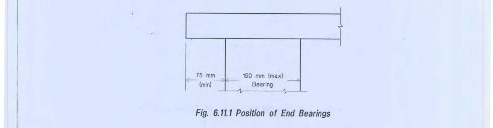
l) No allowance need be made for the difference in intensity of the bearing stress due to bending of a beam.
m) The bearing area should be calculated as the net area after allowance for the amount of wane as permitted in Table 6.11.6.
n) For bearing stress under a washer or a small plate, the same coefficient specified in Table 6.11.11 may be taken for a bearing with a length equal to the diameter of the washer or the width of the small plate.
o) When the direction of the stress is at an angle to the direction of the grain in any structural member, the permissible bearing stress in that member shall be calculated by the following formula.
(11.6.6)
11.6.4 Nail Laminated Beams
11.6.4.1 Method of Arrangement
The beam is made up of 20 to 30 mm thick planks placed vertically with joints staggered in the adjoining planks with a minimum distance of 300 mm. The planks are laminated with the help of wire nails at regular intervals to take up horizontal shear developed in the beam besides keeping the planks in position (see Fig 6.11.2).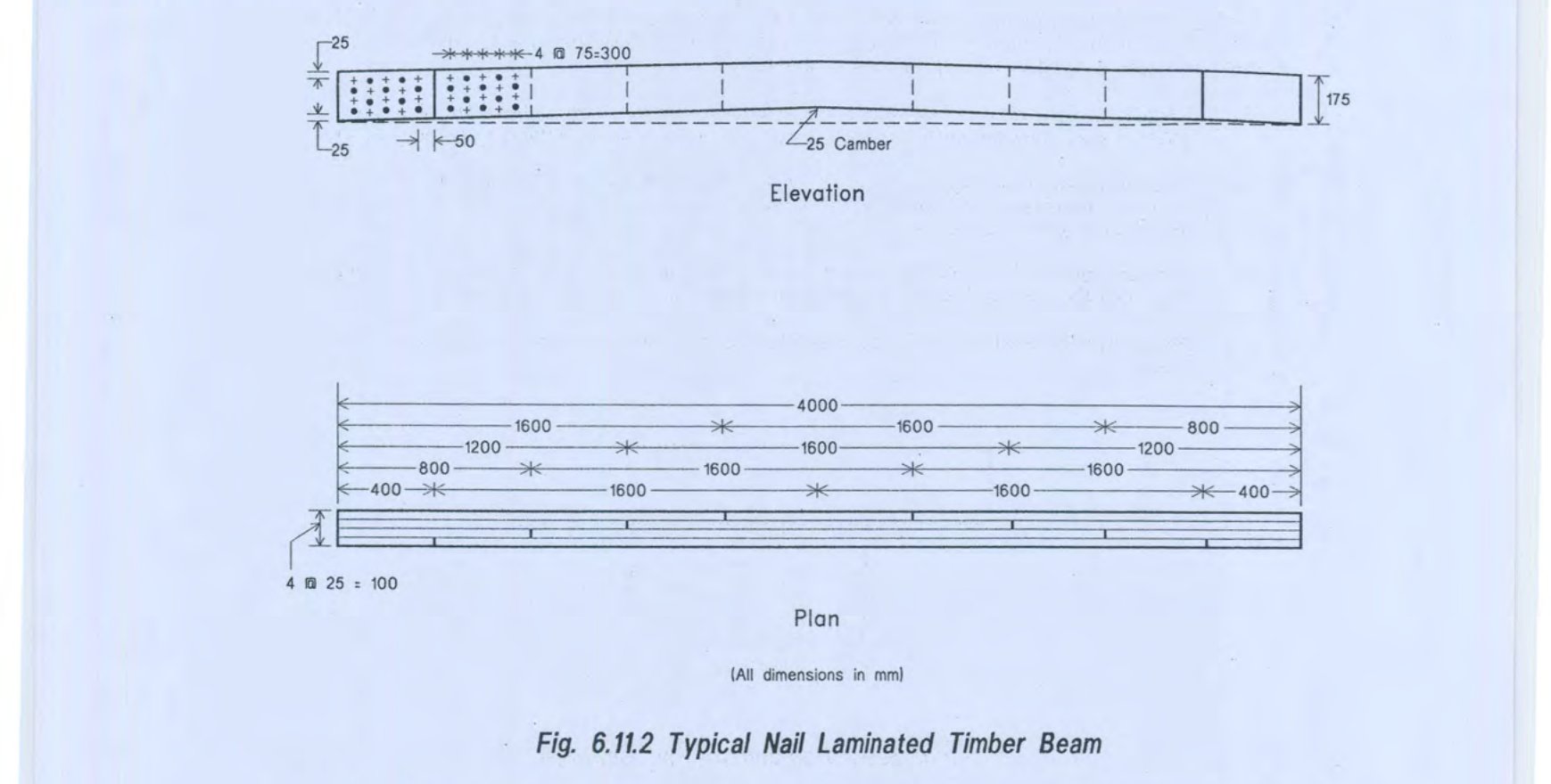
11.6.4.2 Sizes of Planks and Beams
a) The recommended thickness of planks for fabrication of nail laminated beams are 20 mm, 25 mm and 30 mm. b) In case of nail laminated timber beams, the maximum depth and length of planks shall be limited to 250 mm and 2000 mm respectively.11.6.4.3 Design Considerations
a) The provisions of Sec 11.6.1 through 11.6.3 shall also be applicable to the design of nail laminated beams. b) Permissible lateral strength of mild steel wire nails shall be as given in Table 6.11.1 which shall apply to nails that have their points cut flush with the faces. For nails clenched across the grains, the strength may be increased by 20 percent. Table 6.11.12: Number and Size of Planks and Nails for Nail Laminated Beams
Note: A number of combinations of different thickness of planks may be adopted as long as the minimum and maximum thickness of planks are adhered to.
11.6.4.4 Deflection
The deflection in the case of nail laminated timber beams, joists, purlins, battens and other flexural members supporting brittle materials like gypsum, tiles and asbestos sheets shall not exceed ℓ/480. The deflection in the case of other flexural members shall not exceed ℓ/360 of the span in the case of beams and joists, and ℓ/225 in the case of cantilevers.11.6.4.5 Arrangement of Nails
a) A minimum number of four nails in a vertical row at regular interval not exceeding 75 mm shall be used to take up horizontal shear as well as to keep the planks in position. This interval may, however, be limited to 50 mm instead of 75 mm near the joints of the planks. b) Shear shall be calculated at various points of the beam and the number of nails required shall be accommodated within the distance equal to the depth of the beam, with a minimum of 4 nails in a row at a standard spacing as shown in Fig 6.11.3.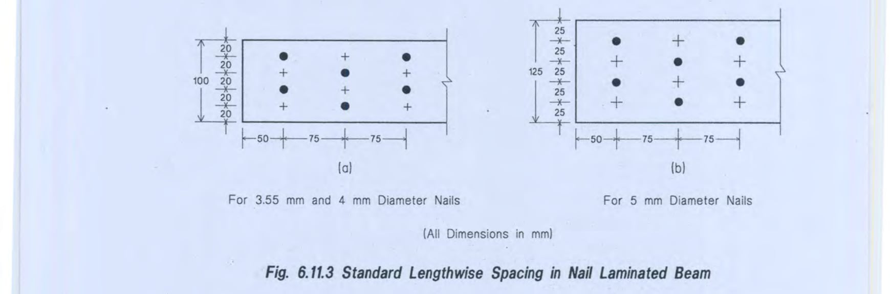
11.7 Columns
11.7.1 Design Consideration
a) The formulae given for columns are for pin-ended condition and they should be modified according to the value of the K_e as given in Table 6.11.13. Table 6.11.13: Values of Design Buckling Factor, K_e for Different End Conditions (S = ℓK_e)
b) In the design of an intermediate or long column, gross section shall be used in calculating load carrying capacity of the column.
11.7.2 Solid Columns
Solid columns shall be classified into short, intermediate and long columns depending upon their slenderness ratio (S/d) as follows: i) Short columns are those where S/d < 11 ii) Intermediate columns are those where 11 ≤ S/d ≤ K_8 iii) Long columns are those where S/d > K_8 a) For short columns, the permissible compressive stress f_pc shall be (11.7.1) b) For intermediate columns the permissible compressive stress f_pc shall be: (11.7.2) c) For long columns, the permissible compressive stress f_pc shall be: (11.7.3) d) In case of solid columns S/d ratio shall not exceed 50. e) The permissible load on a column of circular cross-section shall not exceed that permitted for a square column of an equivalent cross-sectional area.11.7.3 Built-up Columns - Box Columns
a) Box columns shall be classified into short, intermediate and long columns as follows: i) Short columns are those where \frac{S}{\sqrt{d_1^2 + d_2^2}} < 8 ii) Intermediate columns are those where and iii) Long columns are those where \frac{S}{\sqrt{d_1^2 + d_2^2}} > K_9 b) For short columns, the permissible compressive stress f_pc shall be: (11.7.4) c) For intermediate columns, the permissible compressive stress f_pc shall be: (11.7.5) d) For long columns, the permissible compressive stress f_pc shall be: (11.7.6) e) The following values of U which depend upon plank thickness t shall be used in (d) above11.7.4 Built-up Columns - Spaced Columns
The following formula shall be applicable to spaced columns. a) For short columns, the permissible compressive stress f_pc shall be: (11.7.7) b) For intermediate columns the permissible compressive stress shall be (11.7.8) c) For long columns the permissible compressive stress f_pc shall be: (11.7.9) Where the restraint factor C_r shall be determined according to case (i) or case (ii) as explained below and shown in Fig 6.11.4.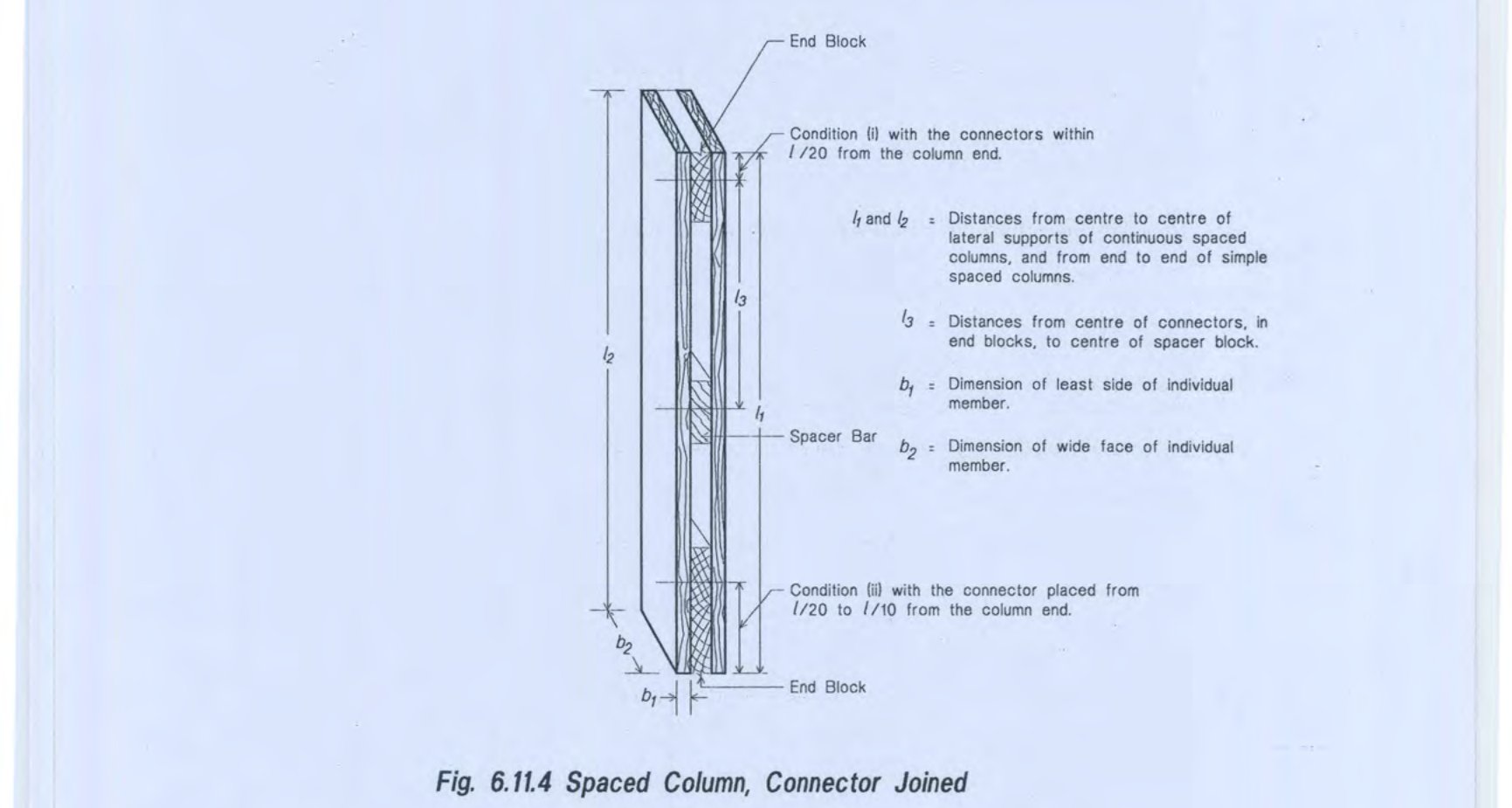
11.7.5 Structural Members Subjected to Bending and Axial Stress
11.7.5.1
Structural members subjected to both bending and axial compression shall be designed to comply with the following formula: (11.7.10)11.7.5.2
Structural members subject to both bending and axial tension shall be designed to comply with the following formula (11.7.11)11.8 Joints
11.8.1 Common Steel Wire Nail Joints
11.8.1.1 Design Consideration
a) Where a number of nails are used in a joint, the allowable load in lateral resistance shall be the sum of the allowable load for the individual nails, provided that the centroid of the group of these nails lie on the axis of the member and the spacing conforms to Sec 11.8.1.5. Where a large number of nails are to be provided at a joint, they shall be arranged that there are more rows than the number of nails in a row. b) Nails shall as far as practicable, be arranged so that the line of force in a member passes through the centroid of the group of nails. Where this is not practicable, allowance shall be made for any eccentricity in computing the maximum load on the fixing nails as well as the loads and bending moment in the member. c) Adjacent nails shall preferably be driven from opposite faces, that is, the nails are driven alternately from either face. d) For a rigid joint, a minimum of 2 nails for nodal joints and 4 nails for lengthening joint shall be driven. e) Two nails in a horizontal row are better than using the same number of nails in a vertical row.11.8.1.2 Dimension of Members
a) The minimum thickness of the main members in mono-chord construction shall be 30 mm. b) The minimum thickness of an individual piece of member in split chord construction shall be 20 mm for web members and 25 mm for chord members. c) The space between two adjacent pieces of timber shall be restricted to a maximum of 3 times the thickness of the individual piece of chord member. In case of web members, it may be greater for joining facilities.11.8.1.3 Joint Location
No lengthening joint shall preferably be located at a panel point. Generally not more than two, but preferably one, lengthening joint shall be permitted between two panel points of the members.11.8.1.4 Specification and Diameter of Nails
a) The diameter of nails shall be within the limit of one-eleventh to one-sixth of least thickness of members being connected. b) The nails shall be galvanized when exposed to saline conditions.11.8.1.5 Arrangement of Nails
The end distances, edge distances and spacing of nail shall not be less than those given in (a) and (b) below so as to avoid undue splitting of timber. a) Lengthening Joints: The requirement of spacing of nails in a lengthening joint shall be as shown in Table 6.11.14 (see Fig 6.11.5). Table 6.11.14: Spacing of Nails in a Lengthening Joint
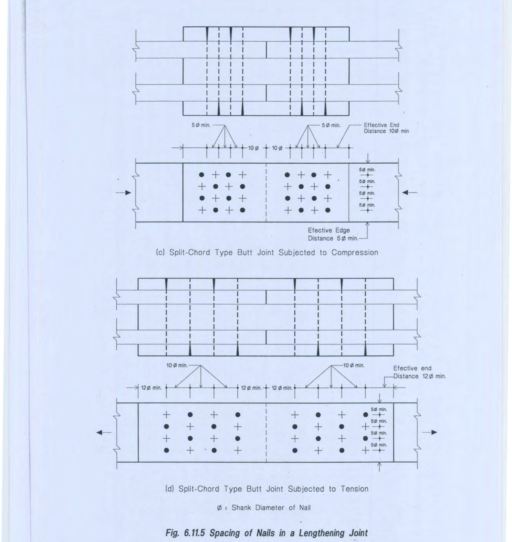
Note: The 5φ distance between rows perpendicular to grain may be increased subject to the availability of width of the member keeping edge distance constant.
b) Node Joints: The requirement of spacing of nails in node joints shall be as specified in Fig 6.11.6 where the members are at right angles and as in Fig 6.11.7 where the members are inclined to one another at angles other than 90° and subject to either pure compression or pure tension.
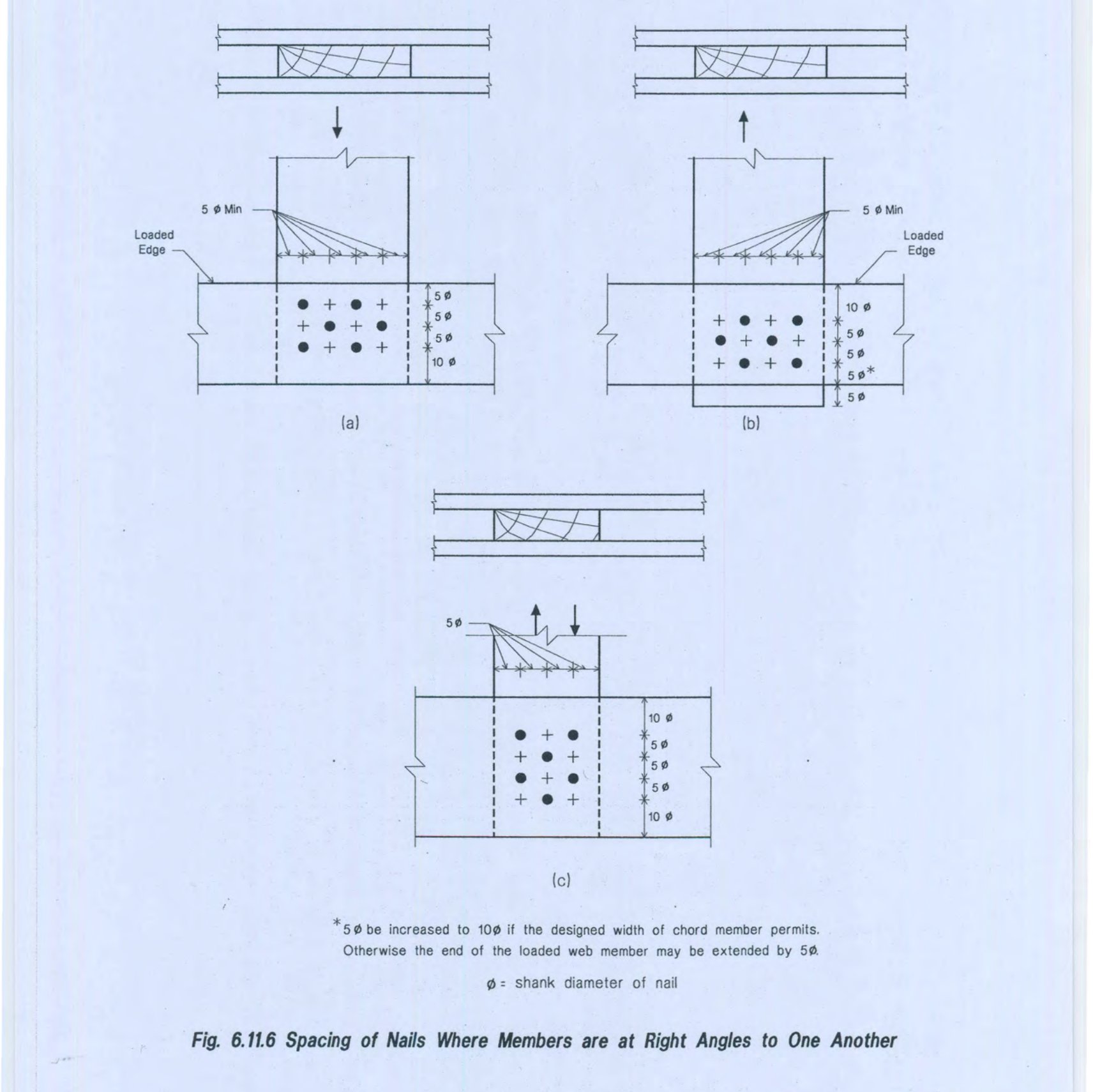
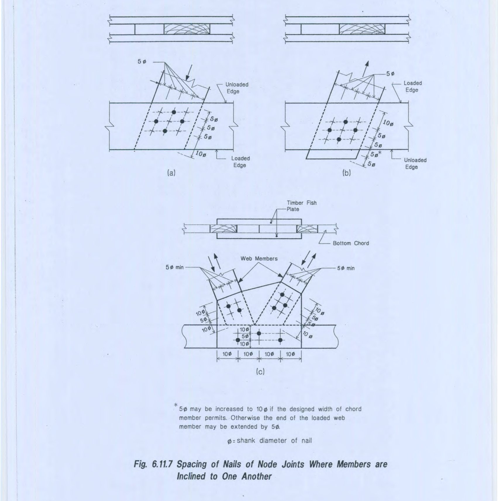
11.8.1.6 Penetration of Nails
a) For a lap joint when the nails are driven from the side of the thinner member, the length of penetration of nails in the thicker member shall be one and a half times the thickness of the thinner member subject to a maximum of the thickness of the thicker member. b) For butt joints the nails shall be driven through the entire thickness of the joint.11.8.1.7 Nail Jointed Truss Construction
a) The slant braced member provided at the centre of the lower chord of nail jointed timber trusses shall not be less than 1/200 for timber structures using seasoned wood and 1/100 for unseasoncd or partially seasoned wood. b) The total combined thickness of the gusset or splice plates on either side of the joint in a mono-chord type construction shall not be less than one and a half times the thickness of the main members subject to a minimum thickness of 25 mm of individual gusset plate. Note 1: The allowable load or lateral strength values of nails shall be as given in Table 6.11.1 Note 2: The strength data for joints given in this section apply to gusset or splice or fish plates of solid wood. However, materials other than solid wood may be used for gusset when field tests are made and their strength requirements have been established.11.8.2 Bolted Joints
11.8.2.1 Design Consideration
a) Beams shall be designed in accordance with Sec 11. 6. b) Where a number of bolts are used in a joint, the allowable load in withdrawal or lateral resistance shall be the sum of the allowable loads for the individual bolts.11.8.2.2 Arrangement of Bolts
a) The following spacing of bolts shall be followed in bolted joints (see Fig 6.11.8).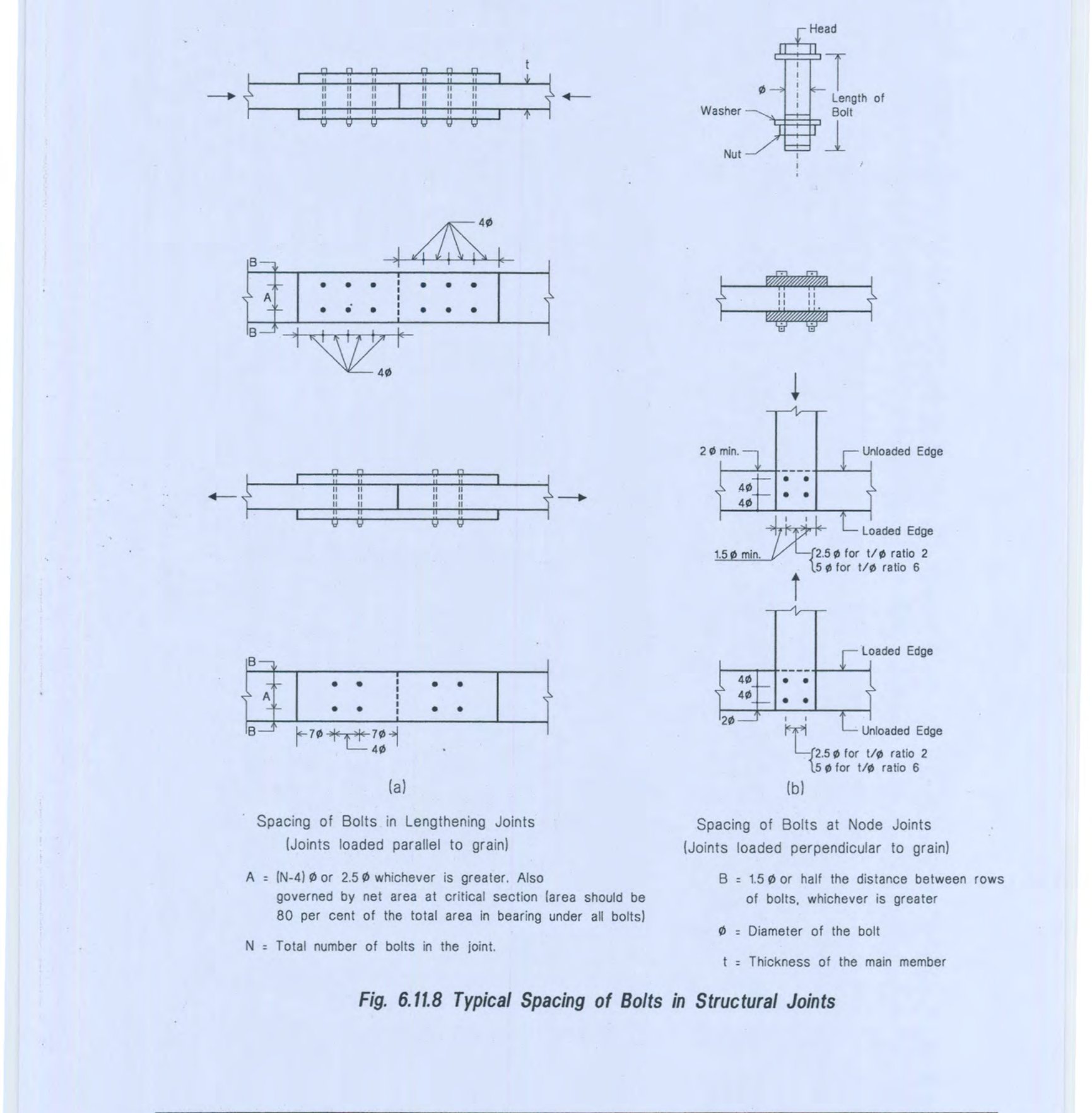
- For perpendicular to grain loading: 2.5φ to 5φ (2.5φ for t/φ ratio of 2 and 5φ for t/φ ratio of 6)
- For parallel to grain loading: At least (N-4)φ with a minimum of 2.5φ, where N is the total number of bolts. Also governed by net area at critical section which shall be 80 per cent of the total area in bearing under all bolts.
- For parallel to grain loading: 1.5φ or half the distance between rows of bolts, whichever is greater.
- For perpendicular to grain loading, the loaded edge distance shall be at least 4φ.