Appendix A: Maximum Demand and Diversity
Some information on the determination of the maximum demand for an electrical installation are provided in this appendix. It also includes some notes on the application of allowances for diversity. It is impossible however, to specify the appropriate allowances for diversity for every type of installation since determination of such allowances calls for special knowledge and experience. The figures shown in Table A1 are therefore, intended to act as guideline. The current demand of a final circuit is determined by summing the current demands of all points of utilization and equipment in the circuit. Typical values to be used for this summation are given in Table A2. For blocks of residential dwellings, large hotels, and industrial and large commercial premises, allowances are to be assigned by a competent engineer. The current demand of a circuit supplying a number of final circuits may be assessed by applying the allowances for diversity given in Table A1 to the total current demand of all the equipment supplied by that circuit. In the table, the allowances are appraised either as percentages of the current demand or, where followed by the letters f.l., as percentages of the rated full load current of the current using equipment. After the design currents for all the circuits have been determined, enabling the conductor sizes to be chosen, it is necessary to check that the limitation on voltage drop is met. Table A1: Allowances for Diversity
Table A2: Current Demand to be Assumed for Points of Utilization and Current using Equipment
Appendix B: Useful Tables Relating to Conductor Sizes
Table B1: Number of Single-core Wire of Different Sizes for Various Sizes of Metal Conduits
Values are number of wires that can be drawn through the conduit diameter shown.
Table B2: Number of Single-core Wires of Different Sizes for Various Sizes of PVC Conduits
Values are number of wires that can be drawn through the conduit diameter shown.
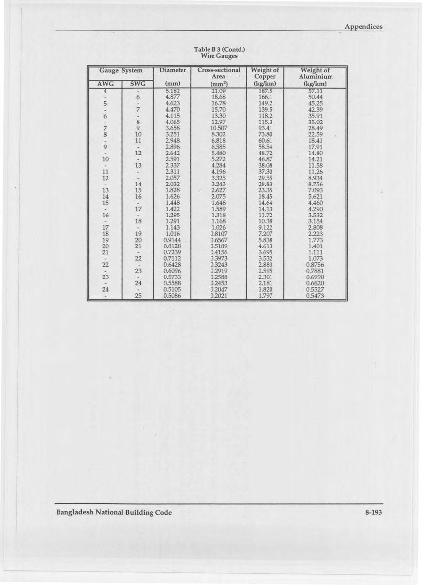
Table B3: Wire Gauges
Table B3 (Contd.): Wire Gauges
Appendix C: Completion Certificate Form (Electrical Works)
I/we certify that the installation detailed below has been installed by me/us and tested and that to the best of my/our knowledge and belief, it complies with the requirements of Bangladesh National Building Code and the Electricity Act of Bangladesh (as modified up to 1987). Header fields: Electrical Installation at ______; Voltage and system of supply ______ Particulars of Works: a) Internal Electrical Installation — for each item below, the form provides columns for No., Total load, and Type or system of wiring: i) Light point ii) Fan point iii) Plug point — 3-pin 5 A; 3-pin 15 A b) Others — for each item below, the form provides columns for Description, hp/kW, and Type of starting:- Motors: i), ii), iii)
- Other plants
- i) Type and description of overhead line; ii) Total length and number of spans; iii) Number of street lights and its description
- i) Total length and size of underground cable; ii) Number of joints — End joint, Tee joint, Straight through joint
Appendix D: Relationship of Weighting Curves for Sound Levels
The standardized weighting curves for sound level meters together with the more recent E and SI curves are shown in the figure below.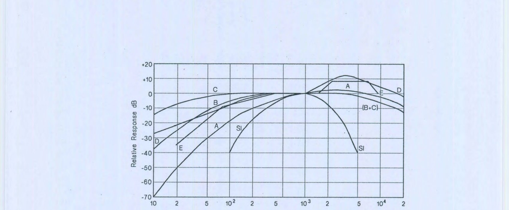
Appendix E: Recommended Optimum Reverberation Time for Assembly Buildings
The recommended optimum reverberation times for various uses of Assembly buildings are given in the figure below.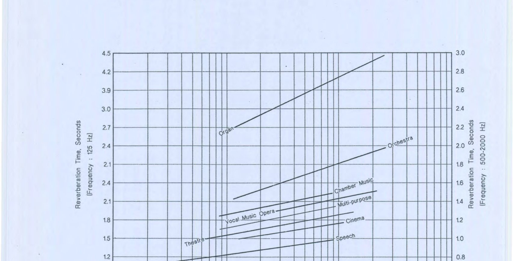
Appendix F: STC Ratings of Walls and Floors
STC ratings of some commonly used walls, floors and structural elements are given in the following Table. Walls
Floors
Appendix G: Air Traffic Noise Levels
For traffic noise levels produced from the aircrafts, control measures shall be initiated from the investigation of the following characteristic features of aircraft noise: a) i) Noise characteristics of different aircraft vary with different power conditions. ii) Noise created by jet aircraft are different from those generated by propeller aircraft with piston engines. iii) Jet noise originates from different parts of the engine, such as the jet, the compressor and the turbine. iv) The typical roar of a flying jet is generated by the violent mixing of the hot exhaust gases with the surrounding air, particularly noticeable during take off and climb. b) After take off the noise level on the ground shall not exceed certain maximum values, for each direction of each runway. These noise levels are higher during the day than at night. c) An angle of 3° or less with the horizontal should be adopted for landing. d) Very long corridor shall be left free of buildings for descending the aircraft before they reach the runway threshold. Airports with runways which continue over water (lake or sea) can follow the noise control requirements much more easily and with added safety. Approximate noise levels due to various types of aircrafts, measured on ground (when the aircraft fly overhead at a height of 450 m) shows that boeing 707 records a maximum noise level of 111 PNdB, followed by Boeing 737 (107 PNdB), Boeing 747 (103 PNdB) and Airbus A 300 (101 PNdB). The flyover noise level for Concorde SST at 450 m with take off thrust is recorded at 114 PNdB, the highest noise level among the commercial aircrafts.Appendix H: Frequency Values and Noise Levels of Some Common Sources
High frequency values have short wavelengths, and are heard as notes of high pitch. Conversely, low frequency sounds have a long wavelength, and are heard as notes of low pitch. A healthy young person is capable of hearing sound from about 20 to 20,000 Hz. Prolonged exposure to intense sound can also cause permanent hearing damage. Short term exposure can cause temporarily losses. Some typical frequencies are mentioned below (in round numbers):
The following are examples of familiar sounds expressed in dB:
Appendix I: Typical Noise Levels in Free-Flowing Road Traffic
Typical noise levels in free-flowing road traffic are given in the following table.
Note: The values are applicable to free-flowing traffic without honking.
Appendix J: Average Air-borne Sound Insulation of Common Constructions
Table J1 below indicates the airborne sound insulation, averaged over the frequency range 100 to 3150 Hz, of a number of common types of constructions. These single figure values must be taken only as a guide because insulation effectiveness depends on how the insulation varies with frequency and because differences in building construction affect the values actually obtained. It must also be remembered that the insulation achieved in practice depends not only on the insulation of the particular dividing element but also on its area in relation to the sound absorption in the rooms, and on indirect transmission. No specific allowance can be made for indirect transmission. However for elements having an insulation of 40 dB or below it will have little effect. In Table J1 the figures above 40 dB allow for the amount of indirect transmission likely to be present when the structures are used in a more or less traditional manner. As to the effects of area and absorption, the values given have been chosen to represent as nearly as possible the achieved insulation between two normally furnished rooms of average proportions when the whole area of the wall or floor is of the specified construction. As a result of these considerations, and owing to variations in detailing and quality of workmanship, it is important to bear in mind that the figures in Table J1 are subject to wide tolerance and must be treated as estimates. Table J1: Average Airborne Sound Insulation of Windows, Walls, Floors etc. Windows
Masonry walls
Note: These estimates refer to insulation of walls between rooms. For insulation between a room and a noise in the open air the overall insulation should be reduced by 5 dB.
Table J1 (Contd.): Average Airborne Sound Insulation of Windows, Walls, Floors etc.
Floors
Dry partitions
Doors
Note: Above 30 dB, specialist doors are needed.
Room to room insulation via suspended ceiling void (Assuming 600 mm deep void, below concrete soffit, no undue obstructions such as large ducts, downstand beams)
Appendix K: Recommended Background Noise Criteria and NC Curves
The NC levels to specify the desirable lowest limits are given in Table K1 and Fig K1. Table K1: Recommended Background Noise Criteria for Rooms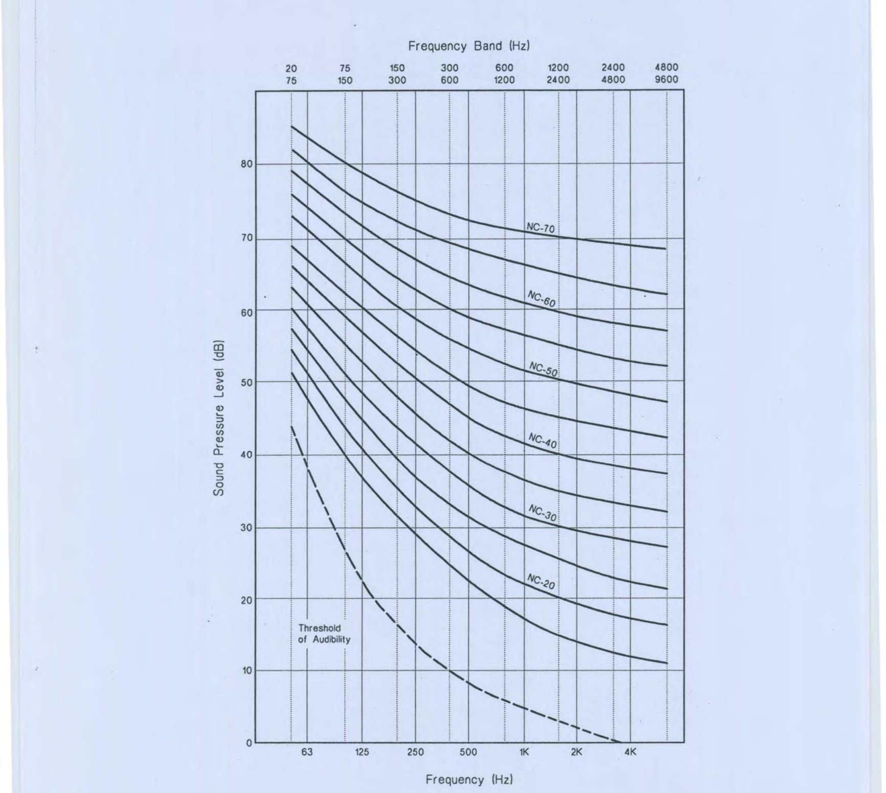
Appendix L: Particulars of Lifts, Escalators and Moving Walks
LIFT — particulars required: a) Number of lifts and capacity of each lift; b) Layout of lift well with sizes; c) Particulars of lift well enclosures; d) Size, position, number and type of landing doors; e) Number of floors served by the lift; f) Height between floor levels; g) Provision of ventilation of lift well; h) Total headroom clearance; i) Location of machine room (above or below lift well), height of machine room; j) Provision of access to machine room; k) Provision of ventilation and, if possible, natural lighting of machine room; l) Depth of lift pit; m) Size and position of supporting steel work at roof levels; n) Size and position of any footings or grillage foundations, if these are adjacent to lift pit; and o) In the case of passenger lifts, whether the lift cage is required to carry heavy household luggage, such as refrigerator, steel almirah, etc. ESCALATOR — particulars required: a) Number of escalators and capacity of each escalator; b) Layout of escalators with dimensions of floor punches; and c) Height between floors. MOVING WALK — particulars required: a) Number of moving walks and capacity of each moving walk; b) Layout of moving walks with dimensions; and c) Length and width of each unit.Appendix M: Format for Particulars of Lifts, Escalators and Moving Walks
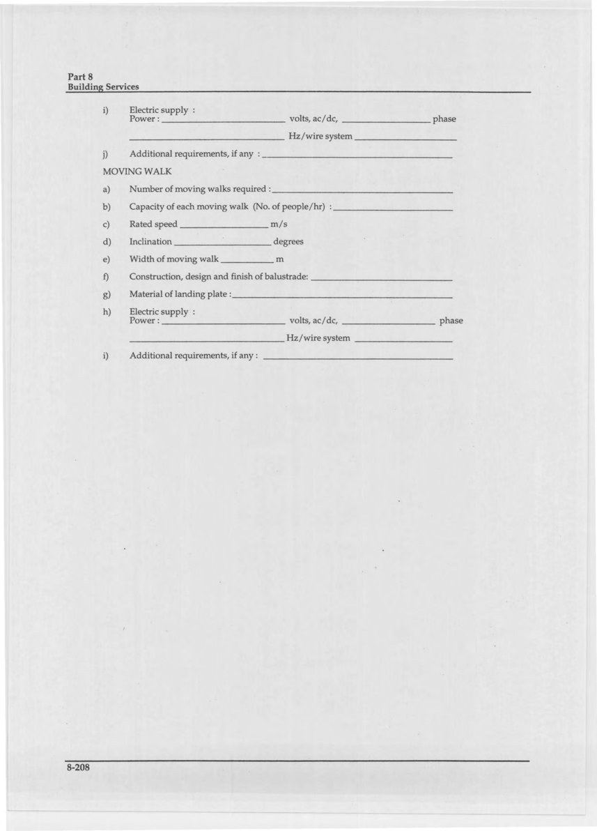
This appendix is a fillable form for submitting the detailed particulars listed in Appendix L. The fields are as follows. LIFTS a) Use: Passenger/Goods/Services/Hospital b) Number of lifts required: ______ c) Capacity per lift: Number of passengers ______ kg ______ d) Rated Speed: ______ m/s e) Travel height: ______ m f) Size and type of car doors: ______ g) Size and type of landing doors: ______ h) Size(s) and location(s) of lift well(s): ______ i) Number of doors: ______ j) Method of control(s): ______ k) Location of machine room: ______ l) Position of counter weight: ______ m) Size of car platform: ______ n) Construction, design and finish of car bodywork: ______ o) Construction, design and finish of car platform: ______ p) Particulars of ventilation of the car: ______ q) Particulars of control buttons in car: ______ r) Particulars of position indicators in car: ______ s) Particulars of call buttons in landing: ______ t) Particulars of car position indicators in landings: ______ u) Electric supply: Power: ______ volts, ac/dc, ______ phase, ______ Hz/wire system ______; Lighting: ______ Volts, ac/dc, ______ Hz/sec v) Additional requirements, if any: ______ ESCALATOR a) Number of escalators required: ______ b) Capacity of each escalator (No. of people/hr): ______ c) Rated speed ______ m/s d) Travel height ______ m, Travel length ______ m e) Width of escalator ______ m f) Construction, design and finish of balustrade: ______ g) Details of steps: ______ h) Materials of landing plate: ______ i) Electric supply: Power: ______ volts, ac/dc, ______ phase ______ Hz/wire system ______ j) Additional requirements, if any: ______ MOVING WALK a) Number of moving walks required: ______ b) Capacity of each moving walk (No. of people/hr): ______ c) Rated speed ______ m/s d) Inclination ______ degrees e) Width of moving walk ______ m f) Construction, design and finish of balustrade: ______ g) Material of landing plate: ______ h) Electric supply: Power: ______ volts, ac/dc, ______ phase ______ Hz/wire system ______ i) Additional requirements, if any: ______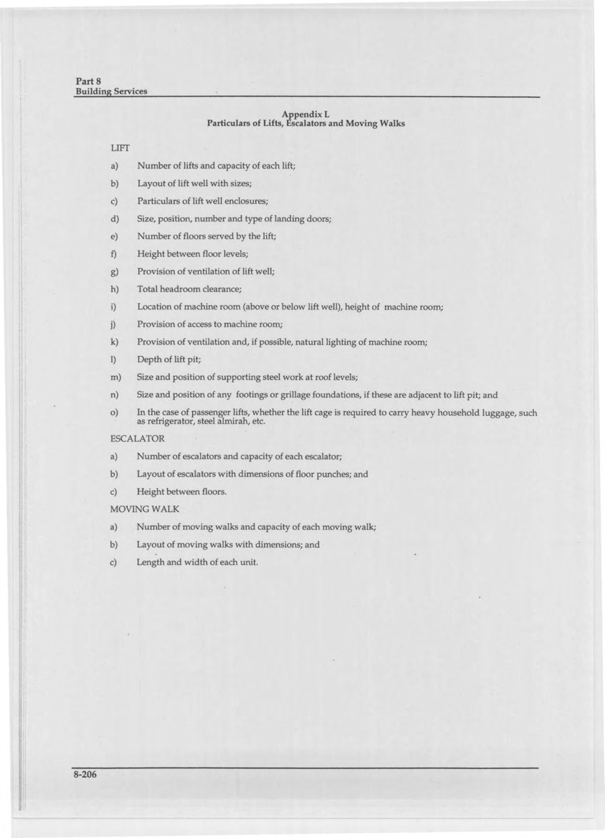
Appendix N: Application for Permit to Construct Water Supply and Distribution System
- Building Location: _____
- Occupancy Classification: _____
- Number of Storeys: _____
- Height of the Building: _____
- This application is accompanied by all required plans, drawing and design calculations (if required) in accordance with Sec 6.3.2 and 6.3.3 of Bangladesh National Building Code.

Appendix P: Sizing of Cold Water Supply and Distribution Piping
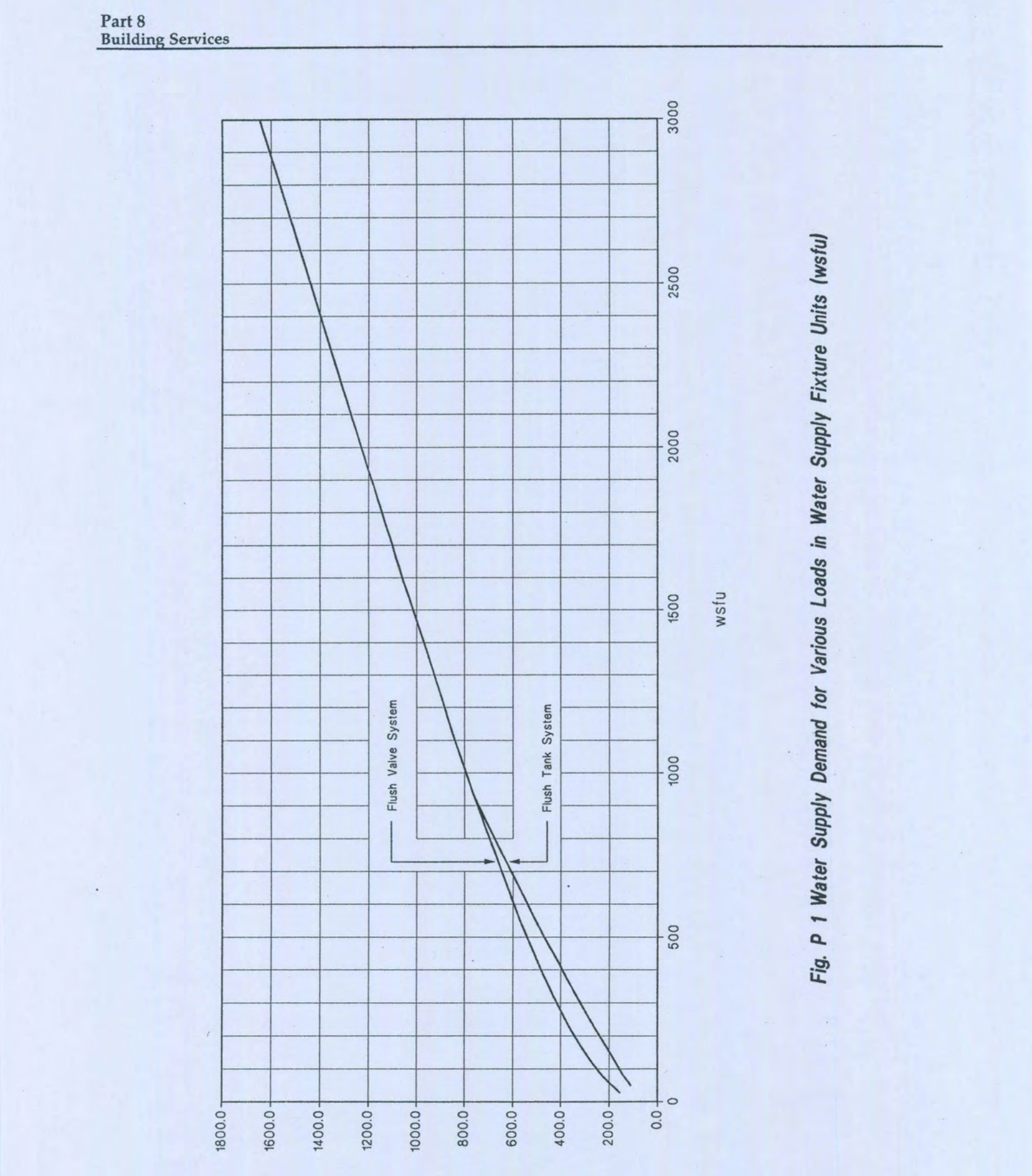
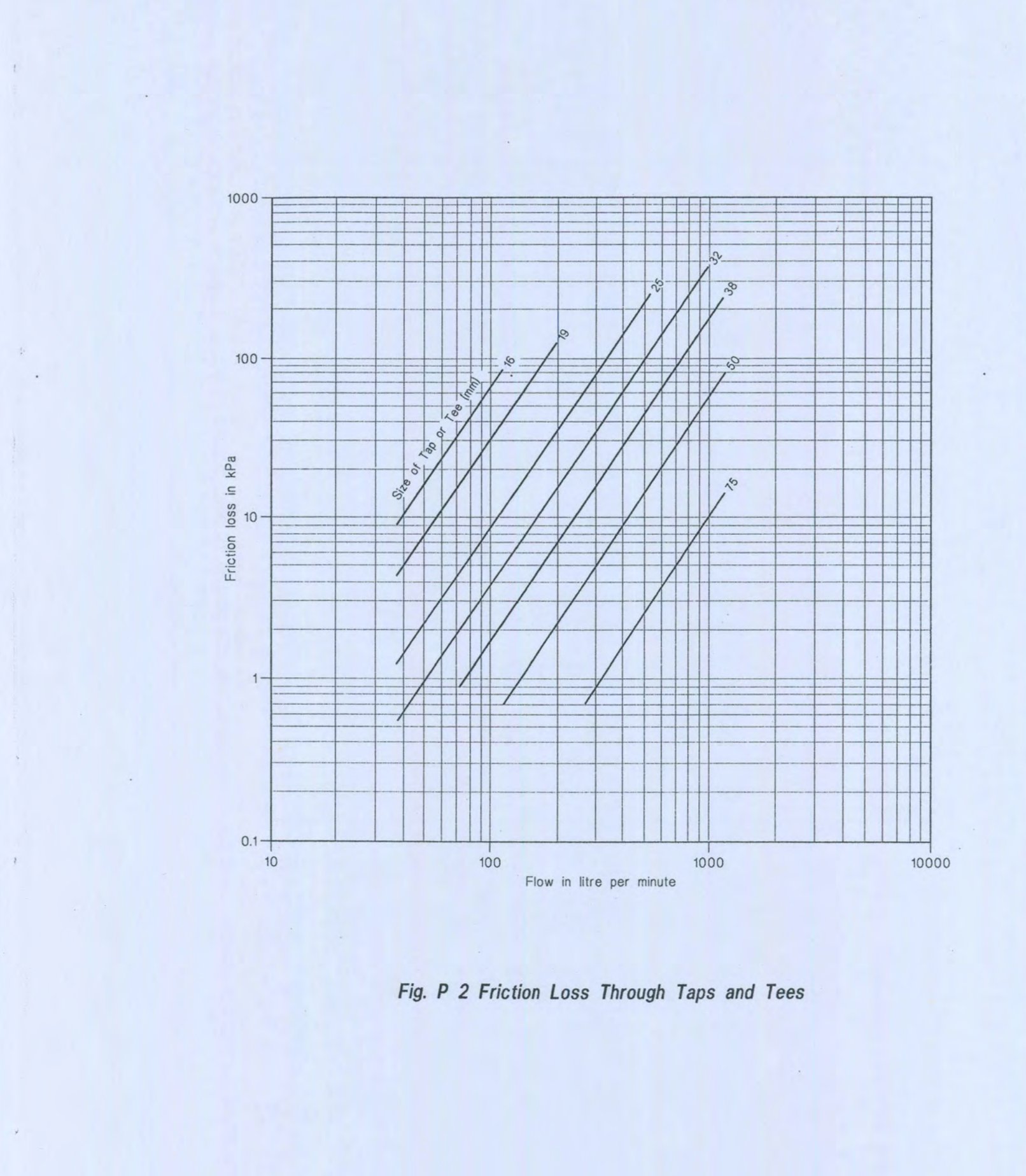
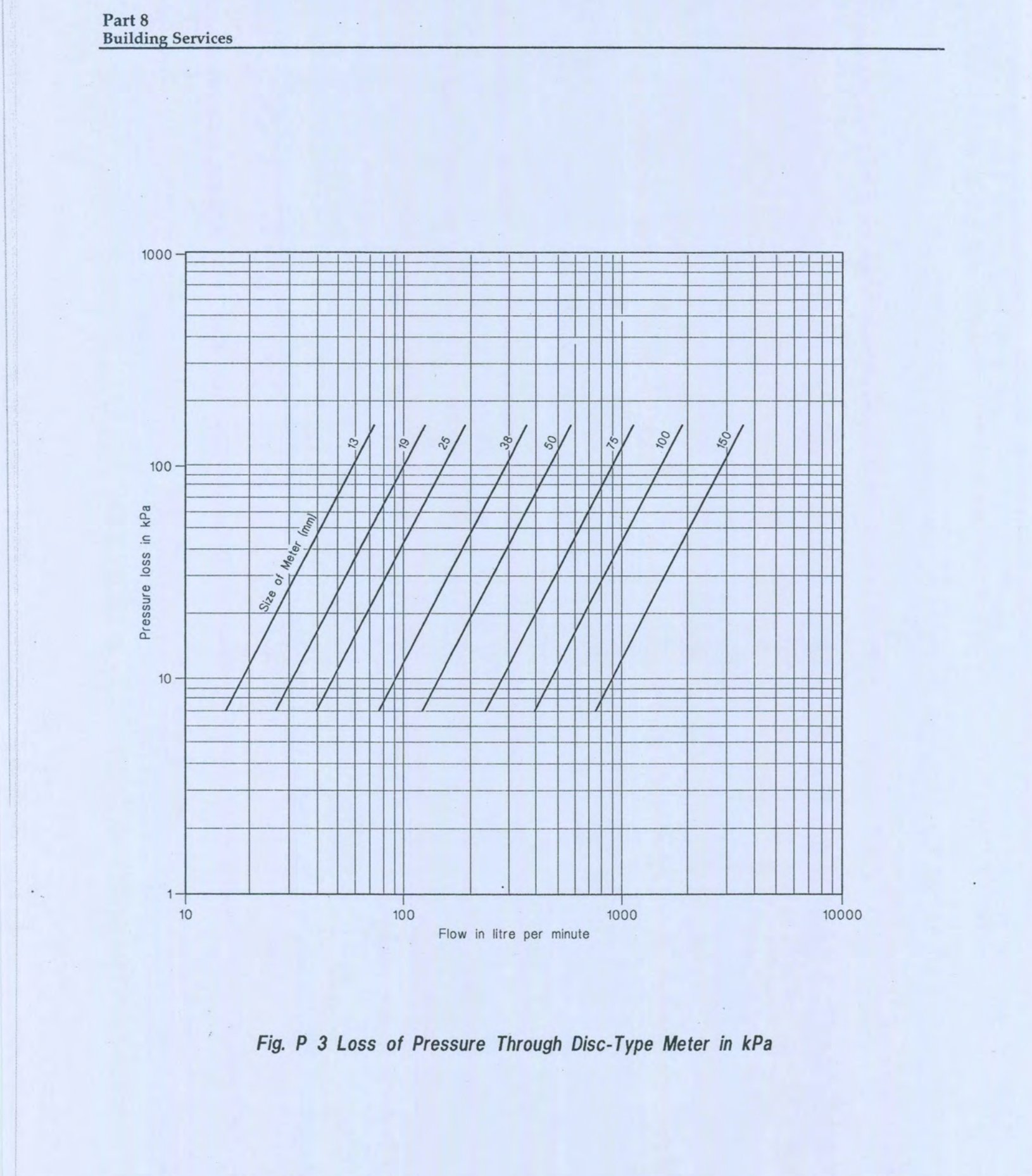
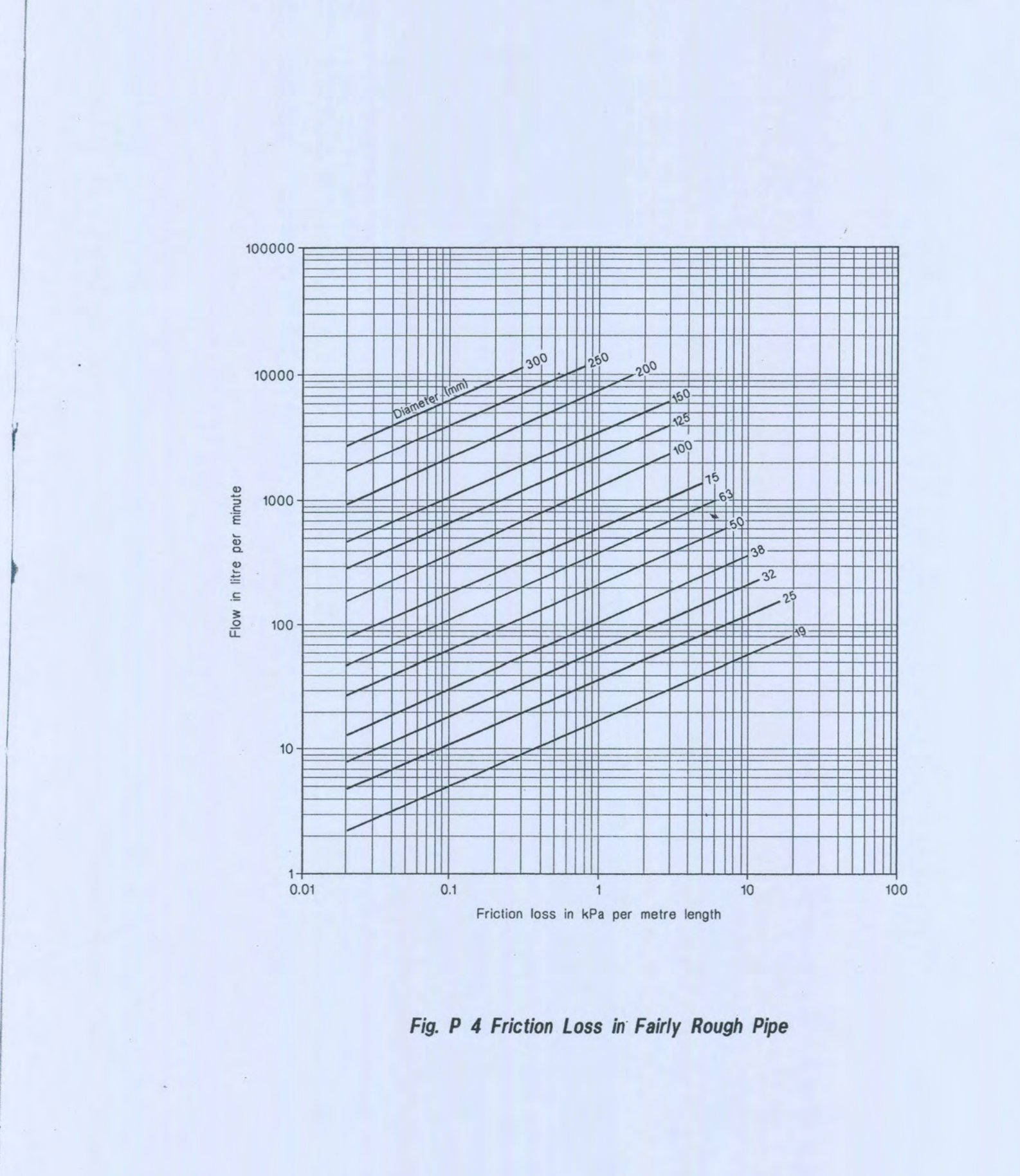
The water distribution within the building may be an upfeed or downfeed system. The design principles are the same for both systems. The principal difference in the calculation procedure is that in the upfeed system, the difference in elevation between the fixtures and the water main exerts the pressure that supplies water into the fixtures, but in the downfeed system the difference in elevation between the fixtures and the roof storage tank provides the pressure to overcome the pipe friction. The following are the recommended pipe sizing procedures: P1 The sketch of the main lines, risers and branches serving different fixtures will have to be drawn. P2 Determine the number and types of fixture that will be required on the basis of the Table 8.7.1 in Chapter 7. P3 The demand weight of different fixture units may be computed in terms of water supply fixture unit (wsfu) in accordance with Table P 1. P4 The peak demand load (or maximum probable flow) in litre per minute may be estimated with the data obtained in P3 using Fig P 1 or on the basis of the number of occupants according to their occupancy classification specified in Table 8.6.1. P5 The equivalent length of the main lines, risers and branches will be determined. The equivalent length of different fittings may be estimated on the basis of the data presented in the Table P 2 and Fig P 2 or from manufacturer’s specification. The total equivalent length is the sum of the equivalent lengths of all pipes and fittings. P6 The pressure loss through water meter may be determined on the basis of their operating characteristics as shown in Fig P 3 (Disk type water meter). The data for other types of water meter may be obtained from the manufacturer. P7 The minimum pressure required at different fixtures to produce adequate flow may be estimated on the basis of the type of fixtures or minimum size of supply pipe in accordance with Table 8.6.4. P8 The average pressure drop in kPa per metre of equivalent pipe length may be computed as follows: where
* + sign is for downfeed system and − sign is for upfeed system
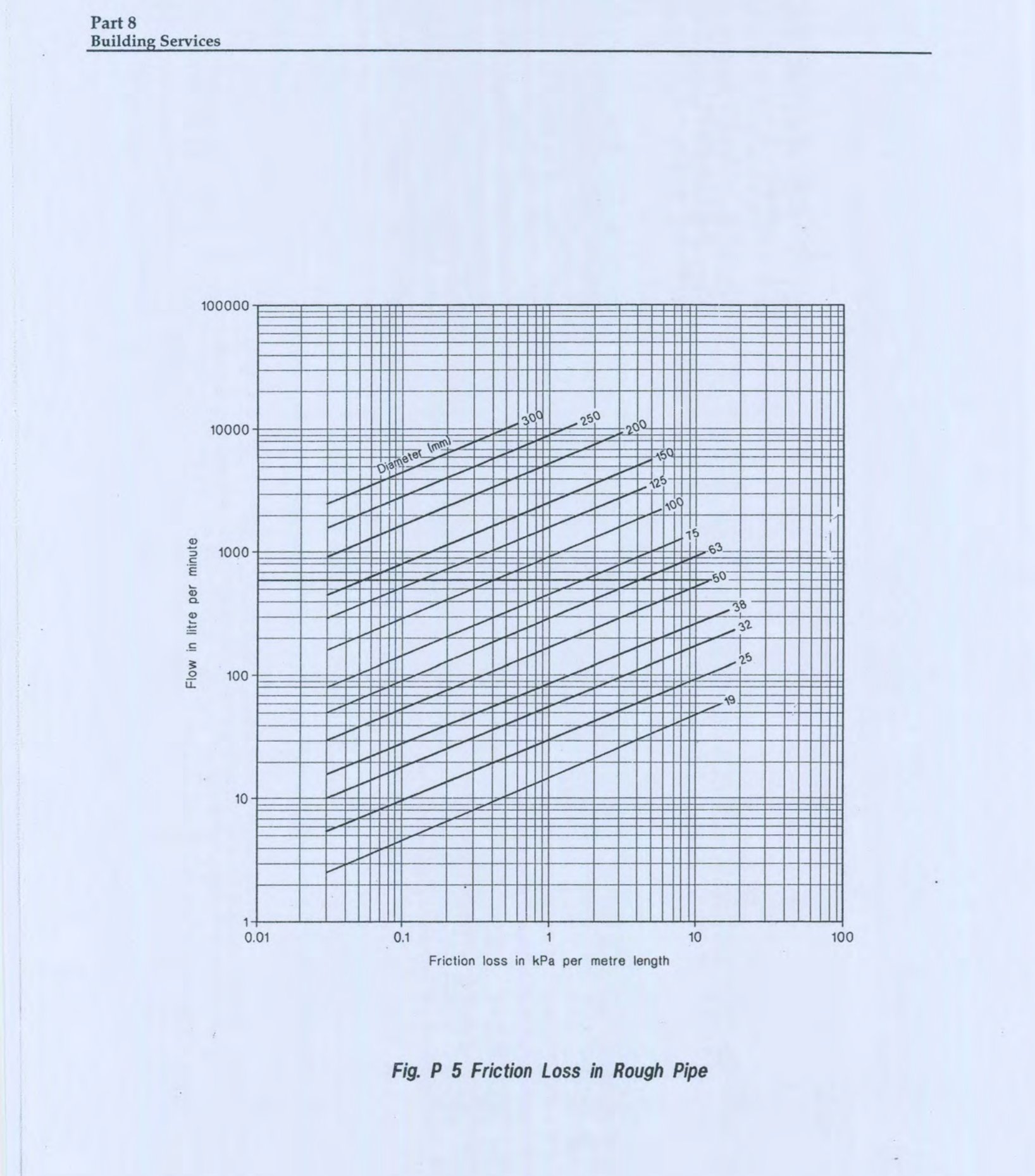
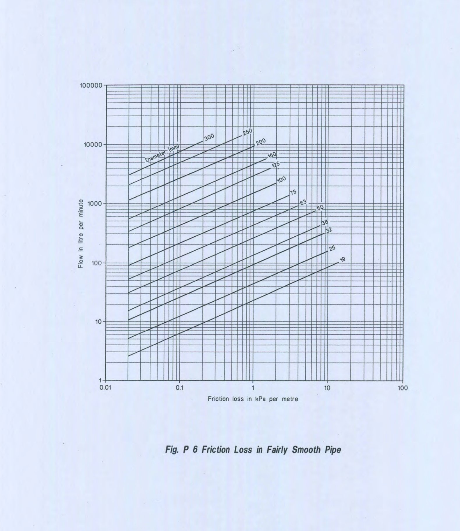
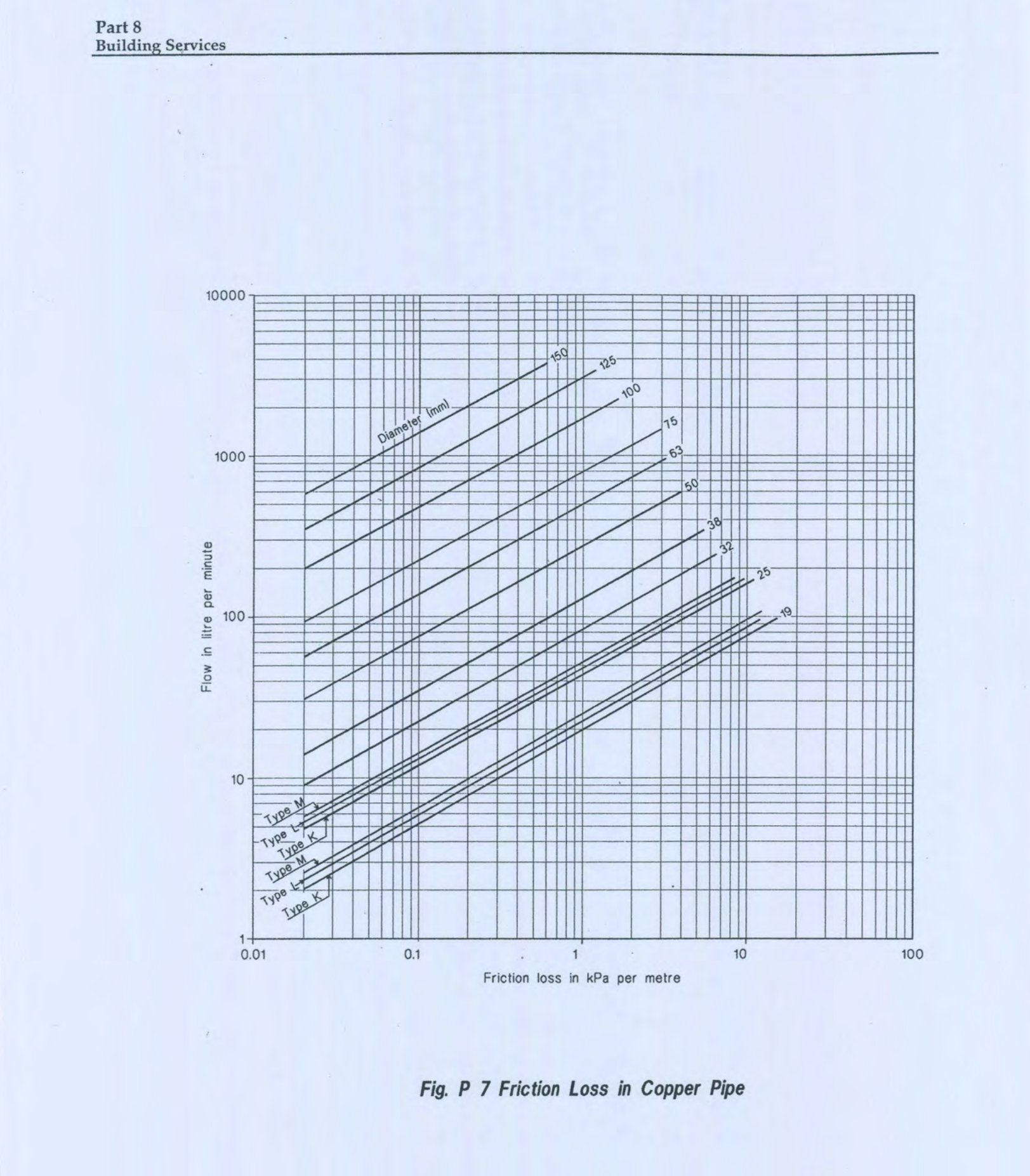
P9 The pipe size may be estimated from Fig P 4 to P 7 for different types of piping materials on the basis of the expected rate of flow determined in P4 and the average pressure available for friction loss (Fp) in P7.
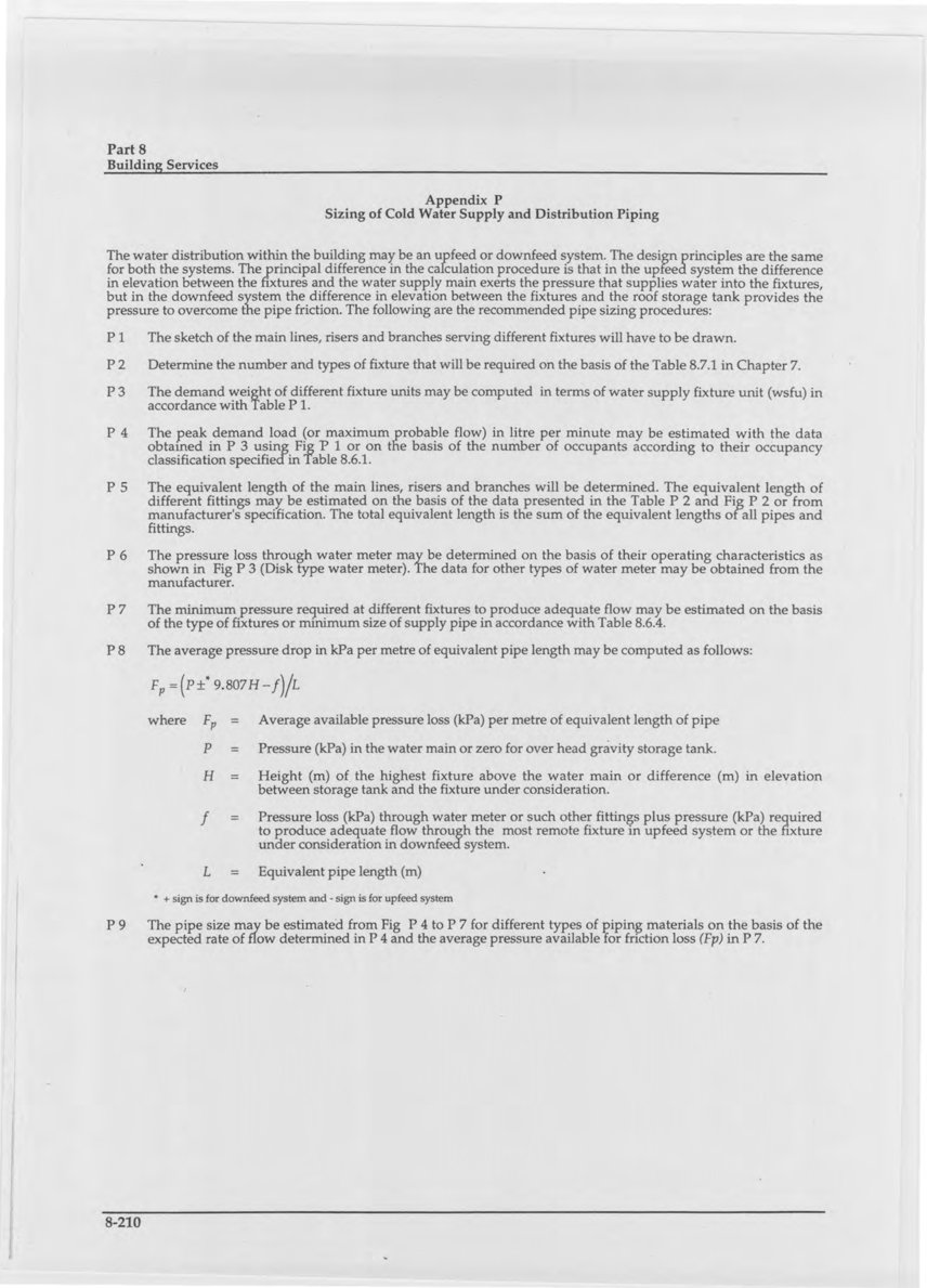
Table P 1: Water Supply Fixture Unit (wsfu) Values for Various Plumbing Fixtures
* Fixture with both cold and hot water supplies, the weight for maximum separate demands may be considered 75% of total wsfu.
Table P 2: Equivalent Length of Pipe for Friction Loss in Valves and Fittings
Equivalent Length (m) of Pipes Against Diameter (mm) of Fittings
Fig P 1 Water Supply Demand for Various Loads in Water Supply Fixture Units (wsfu) — a chart plotting demand in litre per minute (0 to 1800, y-axis) against wsfu (0 to 3000, x-axis), showing two curves labeled “Flush Valve System” and “Flush Tank System” (the Flush Valve System curve reads consistently higher demand for the same wsfu).
Appendix Q: Completion Certificate (Water Supply Works)
Ref. No. of the Authority’s permit: _____ Date: _____ This is to certify that I/We have completed the water supply and distribution system of the building and the premises at: _____ Detail description of the work: _____ This may be inspected, tested and approved. Signature of the licensed plumber — Name and Address: _____ The Authority’s Certificate Certified that the above water supply and distribution system has been completed in accordance with Chapter 6 of Part 8 of the Bangladesh National Building Code. The water supply connection from water main (if any) to the service pipe will be made on _____. Signature of the Building Official or his authorized deputy Seal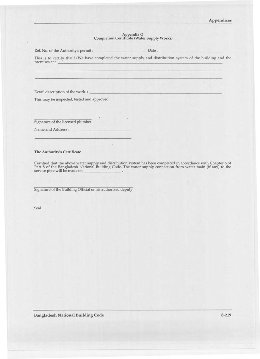
Appendix R: Application for Permit to Construct Drainage and Sanitation System
- Occupancy classification: _____
- Number of storeys: _____
- Location: _____
- This application is accompanied by all required plans, drawings (showing details of materials, sizes, gradient and location of pipes and location of fixtures) and other details as specified in Sec 7.4.2, 7.4.3, 7.4.4 and 7.9.10 of Part 8 of Bangladesh National Building Code.

Appendix S: One-hour Rainfall
One hour rainfall values for a 25-year return period for various locations in Bangladesh may be taken from Fig S 1. The figure shows different regions of equal rainfall intensity as well as isohyets at 5 mm intervals. Rainfall for a particular location shall be obtained as follows: a) When the location lies within any region (shown shaded in the map), the value marked for that region shall be taken. b) For a location lying on any isohyet in this map, the value of that isohyet shall be taken. c) For a location lying outside the positions (a) and (b) above, linear interpolation shall be made between the adjacent isohyets to obtain the required rainfall value.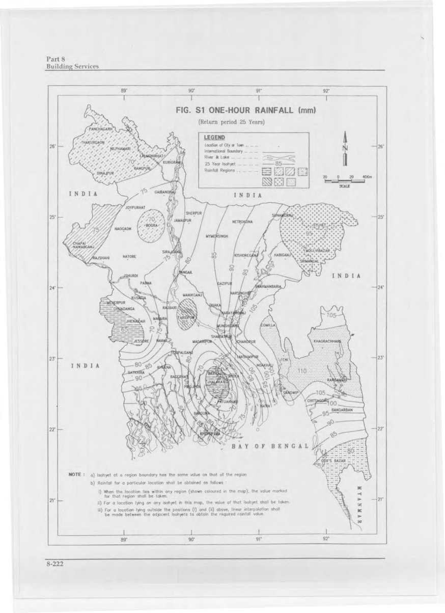
The innermost closed contour near Barisal/Jhalakati/Patuakhali is printed with a value that reads as “55” in the original scan, which is inconsistent with the surrounding 70-100 mm contours in that area. This is likely a misprint in the original gazette.
Appendix T: Design Guideline of a Septic Tank
The volume of a septic tank may be computed using the following equation: where
If computed volume is less than 2000 litres then minimum volume of the septic tank shall be 2000 litre (Sec 7.9.11.8).
Appendix U: Completion Certificate (Drainage and Sanitation Works)
Ref. No. of the Authority’s permit: _____ Date: _____ This is to certify that I/We have completed the drainage and sanitation system for the building and the premises at: _____ Detailed description of the work: _____ This may be inspected, tested and approved. Signature of the plumber — Name and Address: _____ The Authority’s Certificate This is to certify that the above drainage and sanitation system has been completed in accordance with Chapter 7 of Part 8 of the Bangladesh National Building Code. The drainage connection to the main sewer (if any) will be made on _____. Signature of the Building Official or his authorized deputy Seal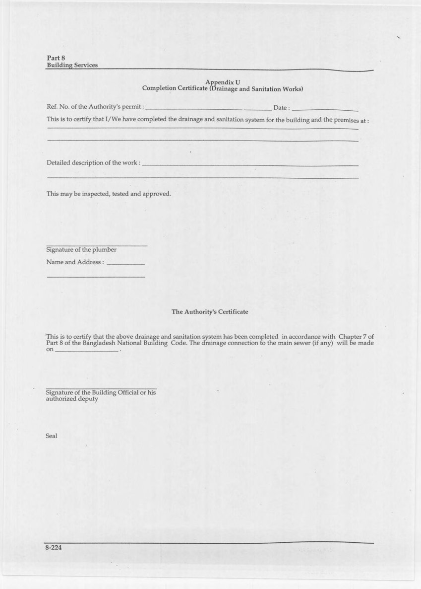
Appendix V: Work on the Gas Supply System
This appendix applies only to work on gas supply systems ahead of the outlet of the meter set assembly, or of the service regulator when there is no meter. Serving Gas Supplier’s Main No person, unless in the employ of or authorized by the gas supply company shall open or make connections with gas main. Serving Gas Piping No person, unless in the employ of or authorized by the gas supply company, shall repair, alter, open or make connections to the services gas piping or do any other work on the parts of the gas supply system up to the meter set assembly or the service regulator when there is no meter. Meter or Service Regulator When a Meter is Not Provided No person, unless in the employ of or authorized by the gas supply company, shall disconnect the inlet of the gas meter or service regulator when there is no meter, nor move such meter or regulator. A gas fitter may disconnect the outlet of such a meter or regulator from the house piping only when necessary. He shall make the joint at the meter or service regulator outlet when there is no meter, carefully replacing all insulating fittings or insulating parts of such fittings, and shall leave the gas turned off at the meter or regulator unless the gas supply company’s rules require or allow deviation from this procedure. Notify Gas Supply Company of any Repairs Needed In case any work done by a gas fitter reveals the need for repairs or alterations on any part of the gas supply system, the gas supply company shall be notified promptly of this fact. Notify Gas Supply Company of any Leakage If gas is leaking from any part of the gas supply system, a gas fitter or plumber not in the employ of the gas supply company may make necessary repairs and shall promptly notify the gas supply company.
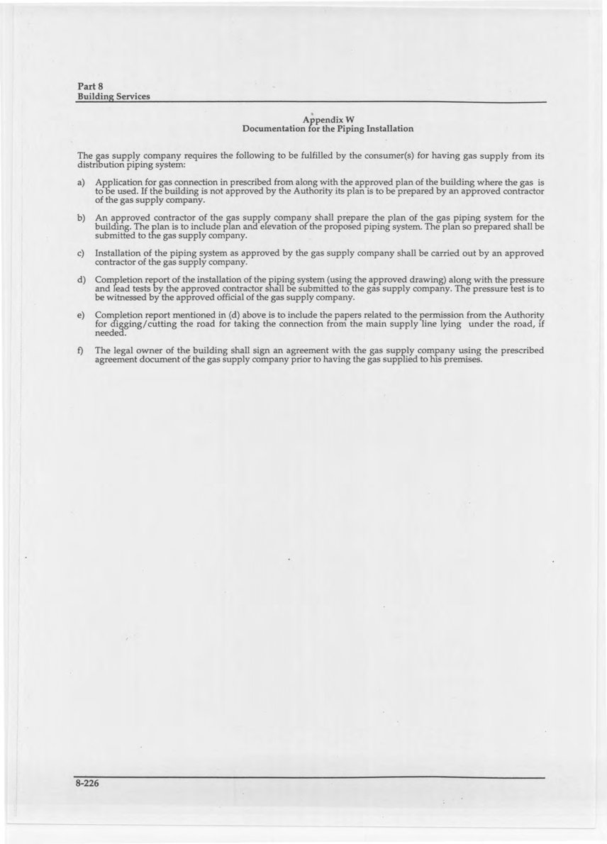
Appendix W: Documentation for the Piping Installation
The gas supply company requires the following to be fulfilled by the consumer(s) for having gas supply from its distribution piping system: a) Application for gas connection in prescribed from along with the approved plan of the building where the gas is to be used. If the building is not approved by the Authority its plan is to be prepared by an approved contractor of the gas supply company. b) An approved contractor of the gas supply company shall prepare the plan of the gas piping system for the building. The plan is to include plan and elevation of the proposed piping system. The plan so prepared shall be submitted to the gas supply company. c) Installation of the piping system as approved by the gas supply company shall be carried out by an approved contractor of the gas supply company. d) Completion report of the installation of the piping system (using the approved drawing) along with the pressure and lead tests by the approved contractor shall be submitted to the gas supply company. The pressure test is to be witnessed by the approved official of the gas supply company. e) Completion report mentioned in (d) above is to include the papers related to the permission from the Authority for digging/cutting the road for taking the connection from the main supply line lying under the road, if needed. f) The legal owner of the building shall sign an agreement with the gas supply company using the prescribed agreement document of the gas supply company prior to having the gas supplied to his premises.