
2.1 INTRODUCTION
2.1.1 Scope
This chapter specifies the minimum design forces including dead load, live load, wind and earthquake loads, miscellaneous loads and their various combinations. These loads shall be applicable for the design of buildings and structures in conformance with the general design requirements provided in Chapter 1.2.1.2 Limitations
Provisions of this chapter shall generally be applied to majority of buildings and other structures subject to normally expected loading conditions. For those buildings and structures having unusual geometrical shapes, response characteristics or site locations, or for those subject to special loading including tornadoes, special dynamic or hydrodynamic loads etc., site-specific or case-specific data or analysis may be required to determine the design loads on them. In such cases, and all other cases for which loads are not specified in this chapter, loading information may be obtained from reliable references or specialist advice may be sought. However, such loads shall be applied in compliance with the provisions of other sections of this Code.2.2 DEAD LOADS
2.2.1 General
The minimum design dead load for buildings and portions thereof shall be determined in accordance with the provisions of this section. In addition, design of the overall structure and its primary load-resisting systems shall conform to the general design provisions given in Chapter 1.2.2.2 Definition
Dead Load is the vertical load due to the weight of permanent structural and non-structural components of a building such as walls, floors, ceilings, permanent partitions and fixed service equipment etc.2.2.3 Assessment of Dead Load
Dead load for a structural member shall be assessed based on the forces due to: i) weight of the member itself, ii) weight of all materials of construction incorporated into the building to be supported permanently by the member, iii) weight of permanent partitions, iv) weight of fixed service equipment, and v) net effect of prestressing.2.2.4 Weight of Materials and Constructions
In estimating dead loads, the actual weights of materials and constructions shall be used, provided that in the absence of definite information, the weights given in Tables 6.2.1 and 6.2.2 shall be assumed for the purposes of design. Table 6.2.1 Unit Weight of Basic Materials
* for reinforced concrete, add 0.63 kN/m³ for each 1% by volume of main reinforcement
Table 6.2.2 Weight of Construction Materials
* for brick aggregate, 90% of the listed values may be used.
2.2.5 Weight of Permanent Partitions
When partition walls are indicated on the plans, their weight shall be considered as dead load acting as concentrated line loads in their actual positions on the floor. The loads due to anticipated partition walls, which are not indicated on the plans, shall be treated as live loads and determined in accordance with Sec 2.3.3.3.2.2.6 Weight of Fixed Service Equipment
Weights of fixed service equipment and other permanent machinery, such as electrical feeders and other machinery, heating, ventilating and air-conditioning systems, lifts and escalators, plumbing stacks and risers etc. shall be included as dead load whenever such equipment are supported by structural members.2.2.7 Additional Loads
In evaluating the final dead loads on a structural member for design purposes, allowances shall be made for additional loads resulting from the (i) difference between the prescribed and the actual weights of the members and construction materials; (ii) inclusion of future installations; (iii) changes in occupancy or use of buildings; and (iv) inclusion of structural and non-structural members not covered in Sec 2.2.2 and 2.2.3.2.3 LIVE LOADS
2.3.1 General
The live loads used for the structural design of floors, roof and the supporting members shall be the greatest applied loads arising from the intended use or occupancy of the building, or from the stacking of materials and the use of equipment and propping during construction, but shall not be less than the minimum design live loads set out by the provisions of this section. For the design of structural members for forces including live loads, requirements of the relevant sections of Chapter 1 shall also be fulfilled.2.3.2 Definition
Live load is the load superimposed by the use or occupancy of the building not including the environmental loads such as wind load, rain load, earthquake load or dead load.2.3.3 Minimum Floor Live Loads
The minimum floor live loads shall be the greatest actual imposed loads resulting from the intended use or occupancy of the floor, and shall not be less than the uniformly distributed load patterns specified in Sec 2.3.3.1 or the concentrated loads specified in Sec 2.3.3.2 whichever produces the most critical effect. The live loads shall be assumed to act vertically upon the area projected on a horizontal plane.2.3.3.1 Uniformly Distributed Loads
The uniformly distributed load shall not be less than the values listed in Table 6.2.3, reduced as may be specified in Sec 2.3.9, applied uniformly over the entire area of the floor, or any portion thereof to produce the most adverse effects in the member concerned.2.3.3.2 Concentrated Loads
The concentrated load to be applied non-concurrently with the uniformly distributed load given in Sec 2.3.3.1, shall not be less than that listed in Table 6.2.3. Unless otherwise specified in Table 6.2.3 or in the following paragraph, the concentrated load shall be applied over an area of 300 mm x 300 mm and shall be located so as to produce the maximum stress conditions in the structural members. In areas where vehicles are used or stored, such as car parking garages, ramps, repair shops etc., provision shall be made for concentrated loads consisting of two or more loads spaced nominally 1.5 m on centres in absence of the uniform live loads. Each load shall be 40 per cent of the gross weight of the maximum size Table 6.2.3 Live Loads for Various Occupancies
Note: (1) w: Uniformly distributed load in kN/m². This load shall not be applied simultaneously with the concentrated load, P.
(2) P: A single concentrated load, in kN, assumed to act over an area of 300 mm x 300 mm unless otherwise specified in Note (5) below. Except as indicated by Note (5), these concentrated loads need not be considered for the floors capable of laterally distributing the load, e.g. reinforced concrete slabs.
(3) Use a distributed load of 2.4 kN/m² for each metre of stack height but not less than 6.5 kN/m².
(4) See Sec 2.3.3.2 for values, numbers, and spacing of these concentrated loads.
(5) These loads shall be applied over an area of 750 mm x 750 mm on all types of floors including reinforced concrete slab.
In areas where vehicles are used or stored, such as car parking garages, ramps, repair shops etc., provision shall be made for concentrated loads consisting of two or more loads spaced nominally 1.5 m on centres in absence of the uniform live loads. Each load shall be 40 per cent of the gross weight of the maximum size vehicle to be accommodated and applied over an area of 750 mm x 750 mm. For the storage of private or pleasure-type vehicles without repair or fuelling, floors shall be investigated in the absence of the uniform live load, for a minimum concentrated wheel load of 9 kN spaced 1.5 m on centres, applied over an area of 750 mm x 750 mm. The uniform live loads for these cases are provided in Table 6.2.3. The condition of concentrated or uniform live load producing the greater stresses shall govern.
2.3.3.3 Provision for Partition Walls
When partitions, not indicated on the plans, are anticipated to be placed on the floors, their weight shall be included as an additional live load acting as concentrated line loads in an arrangement producing the most severe effect on the floor, unless it can be shown that a more favourable arrangement of the partitions shall prevail during the future use of the floor. In the case of light partitions, wherein the total weight per metre run is not greater than 5.5 kN, a uniformly distributed live load may be applied on the floor in lieu of the concentrated line loads specified above. Such uniform live load per square metre shall be at least 33% of the weight per metre run of the partitions, subject to a minimum of 1.2 kN/m².2.3.3.4 More than One Occupancy
Where an area of a floor is intended for two or more occupancies at different times, the value to be used from Table 6.2.3 shall be the greatest value for any of the occupancies concerned.2.3.4 Minimum Roof Live Loads
Roof live loads shall be assumed to act vertically over the area projected by the roof or any portion of it upon a horizontal plane, and shall be determined as specified in the following sections:2.3.4.1 Regular Purpose - Flat, Pitched and Curved Roofs
Live loads on regular purpose roofs shall be the greatest applied loads produced during use by movable objects such as planters and people, and those induced during maintenance by workers, equipment and materials but shall not be less than those given in Table 6.2.4. Table 6.2.4 Minimum Roof Live Loads (1)
Note: (1) Greater of this load and rain load as specified in Sec 2.6.3 shall be taken as the design live load for roof. The distributed load shall be applied over the area of the roof projected upon a horizontal plane and shall not be applied simultaneously with the concentrated load. The concentrated load shall be assumed to act upon a 300 mm x 300 mm area and need not be considered for roofs capable of laterally distributing the load, e.g. reinforced concrete slabs.
2.3.4.2 Special Purpose Roofs
For special purpose roofs, live loads shall be estimated based on the actual weight depending on the type of use, but shall not be less than the following values: a) roofs used for promenade purposes - 3.0 kN/m² b) roofs used for assembly purposes - 5.0 kN/m² c) roofs used for gardens - 5.0 kN/m² d) roofs used for other special purposes - to be determined as per Sec 2.3.52.3.4.3 Accessible Roof Supporting Members
Roof trusses or any other primary roof supporting member beneath which a full ceiling is not provided, shall be capable of supporting safely, in addition to other roof loads, a concentrated load at the locations as specified below: a) Industrial, Storage and Garage Buildings - Any single panel point of the lower chord of a roof truss, or any point of other primary roof supporting member - 9.0 kN b) Building with Other Occupancies - Any single panel point of the lower chord of a roof truss, or any point of other primary roof supporting member - 1.3 kN2.3.5 Loads Not Specified
Live loads, not specified for uses or occupancies in Sec 2.3.3.1 and 2.3.3.2, shall be determined from loads resulting from: a) weight of the probable assembly of persons; b) weight of the probable accumulation of equipment and furniture, and c) weight of the probable storage of materials.2.3.6 Partial Loading and Other Loading Arrangements
The full intensity of the appropriately reduced live load applied only to a portion of the length or area of a structure or member shall be considered, if it produces a more unfavourable effect than the same intensity applied over the full length or area of the structure or member. Where uniformly distributed live loads are used in the design of continuous members and their supports, consideration shall be given to full dead load on all spans in combination with full live loads on adjacent spans and on alternate spans whichever produces a more unfavourable effect.2.3.7 Other Live Loads
Live loads on miscellaneous structures and components, such as handrails and supporting members, parapets and balustrades, ceilings, skylights and supports, and the like, shall be determined from the analysis of the actual loads on them, but shall not be less than those given in Table 6.2.5. Table 6.2.5 Miscellaneous Live Loads
Note: (1) These loads shall be applied non-concurrently along horizontal and vertical directions, except as specified in note (2) below.
(2) These loads shall be applied only in the horizontal direction, uniformly distributed over any length of 1.5 m of a barrier and shall be considered to act at bumper height. For case 2(a) bumper height may be taken as 375 mm above floor level.
(3) Barriers to access ramps of car parks shall be designed for horizontal forces equal to 50% of those given in 2(a) and 2(b) applied at a level of 610 mm above the ramp. Barriers to straight exit ramps exceeding 20 m in length shall be designed for horizontal forces equal to twice the values given in 2(a) and 2(b).
2.3.8 Impact and Dynamic Loads
The live loads specified in Sec 2.3.3 shall be assumed to include allowances for impacts arising from normal uses only. However, forces imposed by unusual vibrations and impacts resulting from the operation of installed machinery and equipment shall be determined separately and treated as additional live loads. Live loads due to vibration or impact shall be determined by dynamic analysis of the supporting member or structure including foundations, or from the recommended values supplied by the manufacture of the particular equipment or machinery. In absence of a definite information, values listed in Table 6.2.6 for some common equipment, shall be used for design purposes. Table 6.2.6 Minimum Live Loads on Supports and Connections of Equipment due to Impact (1)
— Not applicable
Note: (1) All these loads shall be increased if so recommended by the manufacturer. For machinery and equipment not listed, impact loads shall be those recommended by the manufacturers, or determined by dynamic analysis.
2.3.9 Reduction of Live Loads
Reduction of live load is permitted for primary structural members supporting floor or roof, including beam, girder, truss, flat slab, flat plate, column, pier, footing and the like. Where applicable, the reduced live load on a primary structural member shall be obtained by multiplying the corresponding unreduced uniformly distributed live load with an appropriate live load reduction factor, R as listed in Table 6.2.7 and set forth in Sec 2.3.9.1.2.3.9.1 Load Groups
All possible live loads applied on floors and roof of a building due to various occupancies and uses, shall be divided into three load groups as described below for determining the appropriate live load reduction factors. a) Load Group 1: Uniformly distributed live loads arising from the occupancies and uses of (i) assembly occupancies or areas with uniformly distributed live load of 5.0 kN/m² or less, (ii) machinery and equipment for which specific live load allowances have been made, (iii) special roof live load as described in Sec 2.3.4.2, and (iv) printing plants, vaults, strong rooms and armouries, shall be classified under Load Group 1. Reduction of live load shall not be allowed for members or portions thereof under this load group and a reduction factor, R = 1.0 shall be applied for such cases. b) Load Group 2: Uniformly distributed live loads resulting from occupancies or uses of (i) assembly areas with uniformly distributed live load greater than 5.0 kN/m², and (ii) storage, mercantile, industrial and retail stores, shall be classified under Load Group 2. Live load reduction factor, shall be applied to this load group depending on the tributary area of the floors or roof supported by the member as specified in Sec 2.3.9.3. c) Load Group 3: Uniformly distributed live loads arising due to all other occupancies and uses except those of Load Group 1 and Load Group 2, shall be grouped into Load Group 3. Live load reduction factor, as specified in the Sec 2.3.9.3, shall be applied to tributary areas under this load group.2.3.9.2 Tributary Area
The tributary area of a structural member supporting floors or roof shall be determined as follows: a) Tributary Area for Wall, Column, Pier, Footing and the like: Tributary areas of these members shall consist of portions of the areas of all floors, roof or combination thereof that contribute live loads to the member concerned. b) Tributary Area for Beam, Girder, Flat plate and Flat slab: Tributary area for such a member shall consist of the portion of the roof or a floor at any single level that contributes loads to the member concerned. Table 6.2.7 Live Load Reduction Factors for Various Occupancies and UsesTable 6.2.7, Load Group 2: the tributary-area sequence reads 50/60/80/100/120/140/280/220/300/400/≥800 in the source page image itself (page 6-26). Independently re-verified directly against page_279.png: the digits are unambiguously “280” (not 180, 208, or any other misreading), printed out of numerical order between 140 and 220. This is transcribed verbatim as it appears in the source; it is likely a typesetting error in the original gazette (compare the strictly increasing sequence in Load Group 3), not an extraction artifact.
2.3.9.3 Determination of Reduced Live Load
The value of the live load reduction factor, R shall depend on the load group specified in Sec 2.3.9.1 and on the tributary area of the floor or the roof and combination thereof supported by a primary structural member. The reduced live load on a structural member shall be determined using the following steps: a) Portions of the tributary area pertaining to each of the three load groups specified in Sec 2.3.9.1 shall be identified and summed up, and a value of the reduction factor R shall be obtained from Table 6.2.7 corresponding to each portion of the tributary area, b) The reduced live loads or load intensities shall then be obtained for each load group by multiplying the unreduced live loads or load intensities by the corresponding reduction factors, and finally, c) The total reduced live load on a structural member shall be determined by summing up the reduced live loads from each load group.2.4 WIND LOADS
2.4.1 General
The minimum design wind load on buildings and components thereof, shall be determined based on the velocity of the wind, the shape and size of the building and the terrain exposure condition of the site as set forth by the provisions of this section. For the overall design of structures, the general design requirements as specified in Chapter 1 shall also be fulfilled.2.4.1.1 Scope
Provisions of this section shall apply to the calculation of design wind loads for the primary framing systems and for the individual structural components and cladding of buildings. The design wind load shall include the effects of the sustained wind velocity component and the fluctuating component due to gusts. For slender buildings, the design wind load shall also include additional loading effects due to wind induced vibrations of the building.2.4.1.2 Limitations
Provisions of this section shall include forces due to along-wind response of regular-shaped buildings, caused by the common wind-storms including cyclones, thunder-storms and norwesters. However, the following cases shall remain beyond the scope of these provisions: a) forces due to cross-wind response of buildings and structures, b) forces, such as torsion etc. generated due to unusual or unsymmetrical geometry of the building, and c) forces generated due to special types of winds, such as tornadoes. For calculation of wind loads arising due to the above special cases and for buildings requiring more accurate loading information, reference shall be made to reliable literature pertaining to these loads, or specialist advice shall be sought.2.4.2 Definitions
The following definitions shall apply only to the provisions of Sec 2.4. AWNINGS (e.g. PORCH COVER): A roof-like structure, usually of limited extent, projecting from a wall of a building. BASIC WIND SPEED, : Fastest-mile wind speed in km/h corresponding to the level of 10 metres above the ground of terrain Exposure-B defined in Sec 2.4.4 and associated with an annual probability of occurrence of 0.02. BUILDINGS: Structures that enclose a space and are used for various occupancies. CANOPY: A roof adjacent to or attached to a building, generally not enclosed by walls. COMPONENTS AND CLADDING: Structural elements that are either directly loaded by the wind or receive wind loads originating at relatively close locations and transfer those loads to the primary framing system. Examples include curtain walls, exterior glass windows and panels, roof sheeting, purlins, grits, studs, and roof trusses. CYCLONE: An intense low-pressure centre accompanied by heavy rain and gale-force winds. It forms over warm tropical oceans and decays rapidly over land. DESIGN WIND PRESSURES, : Equivalent static pressure due to wind including gusts to be used in the determination of wind loads for buildings. The pressure shall be assumed to act in a direction normal to the surface considered and is denoted as: = pressure that varies with height in accordance with the sustained wind pressure evaluated at height , or = pressure that is uniform with respect to height as determined by the sustained wind pressure evaluated at mean roof height . ENCLOSED BUILDING: Buildings which have full perimeter wall (nominally sealed) from floor to roof level. ESSENTIAL FACILITIES: Buildings and structures which are necessary to remain functional during an emergency or a post disaster period. FASTEST-MILE WIND SPEED: The highest sustained average wind speed in km/h based on the time required for a mile-long sample of air to pass a fixed point. FREE STANDING ROOF: A roof (of any type) with no enclosing walls underneath, e.g. freestanding carport. FREESTANDING WALLS: Walls which are exposed to the wind on both sides, with no roof attached, e.g. fences. GABLED FRAME: A rigid frame having vertical side members and a sloped top with a ridge. GRADIENT HEIGHT: Height from the mean ground level above which the variation of wind speed with height need not be considered. HOARDING: Free standing (rectangular) signboards, etc., supported clear of the ground. ISOTACH: A line on a map joining points of equal wind speed. MOONSCAPE ROOF: A planar roof with no ridge, which has a constant slope. OPENINGS: Apertures or holes in the exterior walls of a building or structure. Doors or other openings in exterior walls shall be considered as openings unless such openings and their frames are specifically detailed and designed to resist the wind loads in accordance with the provisions of this section. PITCHED ROOF: A bi-fold, bi-planar roof with a ridge at its highest point. PRESSURE: Air pressure in excess of ambient. Negative values are less than ambient and positive values exceed ambient. Net pressures act normal to a surface in the specified direction. PRIMARY FRAMING SYSTEM: An assemblage of major structural elements assigned to provide support for secondary members and cladding. The system primarily receives wind loading from relatively remote locations. Examples include rigid and braced frames, space trusses, roof and floor diaphragms, shear walls, and rod-braced frames. SLENDER BUILDINGS AND STRUCTURES: Buildings and structures having a height exceeding five times the least horizontal dimension, or a fundamental natural frequency less than 1.0 Hz. For those cases in which the horizontal dimensions vary with height, the least horizontal dimension at mid-height shall be used. STRUCTURES: See Sec 1.2.2. STRUCTURE IMPORTANCE COEFFICIENT, : A factor that accounts for the degree of hazard to human life and damage to property. SUSTAINED WIND PRESSURE, : The theoretically computed incident pressure of a uniform air stream (fastest-mile speed) of known density, evaluated at a given height above ground level, for a specific terrain exposure condition and for a known occupancy of a building. TERRAIN: The surface roughness condition when considering the size and arrangement of obstructions to wind. TOPOGRAPHY: Major land surface features comprising hills, valleys and plains which strongly influence wind flow patterns. TORNADO: A violently rotating column of air, pendant from the base of a connective cloud, and often observable as a funnel cloud attached to the cloud base. TRIBUTARY AREA: That portion of the surface area receiving wind loads assigned to be supported by the structural element considered. TROUGH ROOF: A bi-fold, bi-planar roof with a valley at its lowest point. UNENCLOSED BUILDING OR STOREY: A building or storey which has 85% or more openings on all sides.2.4.3 Symbols and Notation
The following symbols and notation shall apply to the provisions of Sec 2.4 only:2.4.4 Terrain Exposure
A terrain exposure category that adequately reflects the surface roughness characteristics of the ground shall be determined for the building site, taking into account the variations in ground roughness arising from existing natural topography, vegetation and manmade constructions.2.4.4.1 Exposure Category
The terrain exposure in which a building or structure is to be sited shall be assessed as being one of the following categories: a) Exposure A: Urban and sub-urban areas, industrial areas, wooded areas, hilly or other terrain covering at least 20 per cent of the area with obstructions of 6 metres or more in height and extending from the site at least 500 metres or 10 times the height of the structure, whichever is greater. b) Exposure B: Open terrain with scattered obstructions having heights generally less than 10 m extending 800 m or more from the site in any full quadrant. This category includes air fields, open park lands, sparsely built-up outskirts of towns, flat open country and grasslands. c) Exposure C: Flat and unobstructed open terrain, coastal areas and riversides facing large bodies of water, over 1.5 km or more in width. Exposure C extends inland from the shoreline 400 m or 10 times the height of structure, whichever is greater.2.4.4.2 Selection of Exposure Category for Primary Framing System
Design wind load for primary framing systems for all buildings and structures shall be determined based on the terrain exposure categories defined in Sec 2.4.4.1.2.4.4.3 Selection of Exposure Category for Components and Cladding
Design wind load on the components and cladding of all buildings and structures shall be determined on the basis of the exposure category defined in Sec 2.4.4.1, except that Exposure B shall be assumed for buildings or structures having m and sited in a terrain with Exposure A.2.4.5 Basic Wind Speed
2.4.5.1 Basic Wind Speed Map
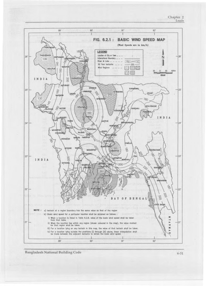
The Basic Wind Speed Map as shown in Fig 6.2.1 is the map showing the basic wind speeds in km/h for any location in Bangladesh, having isotachs representing the fastest-mile wind speeds at 10 metres above the ground with terrain Exposure B for a 50-year recurrence interval. The minimum value of the basic wind speed set in the map is 130 km/h. Basic wind speeds for selected locations are also provided in Table 6.2.8.2.4.5.2 Selection of Basic Wind Speed
Value of the basic wind speed required for any specific location where a building or structure is sited, shall be obtained as follows: i) When the location is listed in Table 6.2.8, value of the basic wind speed shall be taken from that table. ii) If the location lies within any wind region (shown shaded in the map of Fig 6.2.1), the value marked for that wind region shall be used. iii) For a location lying on any isotach in the map, the value of that isotach shall be taken. iv) For a location lying outside the positions (i) through (iii) above, linear interpolation shall be made between the adjacent isotachs to obtain the basic wind speed. For areas where local records or terrain conditions indicate higher values of basic wind speeds (substantiated by site-specific analysis) than those reflected in Fig 6.2.1 and Table 6.2.8, the site-specific values shall be adopted as the minimum basic wind speeds.2.4.6 Determination of Design Wind Loads
2.4.6.1 Basis of Wind Load Calculation
The minimum design wind load on buildings, structures and components thereof shall be calculated, within the scope and limitations given in Sec 2.4.1 taking into account the following effects which shall be determined in accordance with the provisions of this section: a) equivalent static pressure or suction on building surfaces arising due to the sustained or mean wind velocity, i.e. the fastest-mile wind speed, b) variation of the mean wind velocity, and hence the pressure, along the height above the ground, c) terrain exposure of the building site, d) configuration and dynamic response characteristics of the building or structure, e) occupancy importance of the building, f) magnification of the mean wind pressure due to the effect of the fluctuating component of wind speed, i.e. gusts, and g) additional load amplification resulting from the dynamic wind-structure interaction effects due to gusts on slender buildings and structures.2.4.6.2 Sustained Wind Pressure
The sustained wind pressure, on a building surface at any height z above ground shall be calculated from the following relation: where, = sustained wind pressure at height z, kN/m² = structure importance coefficient as given in Table 6.2.9 = velocity-to-pressure conversion coefficient = = combined height and exposure coefficient as given in Table 6.2.10 = basic wind speed in km/h obtained from Sec 2.4.5 If a structure is located within a local topographic zone, shall be modified in accordance with Sec 2.4.6.8. Table 6.2.8: Basic Wind Speeds for Selected Locations in Bangladesh
Table 6.2.9: Structure Importance Coefficients, for Wind Loads
Table 6.2.10: Combined Height and Exposure Coefficient,
Note (1): Linear interpolation is acceptable for intermediate values of z.
2.4.6.3 Design Wind Pressure
The design wind pressure, for a structure or an element of a structure at any height, z above mean ground level shall be determined from the relation: where, = design wind pressure at height z, kN/m² = gust coefficient which shall be , , or as set forth in Sec 2.4.6.6 = pressure coefficient for structures or components as set forth in Sec 2.4.6.7 = sustained wind pressure obtained from Eq (2.4.1).2.4.6.4 Design Wind Load for Buildings and Structures
Design wind load on the main wind force resisting systems of buildings and structures shall be determined by using one of the following two methods: a) Method 1 (Surface Area Method): The surface area method shall be used for gabled rigid frames and single storey rigid frames and may be used for other framing systems. In this method the design wind pressures shall be assumed to act simultaneously normal to all exterior surfaces including roof of buildings or structures. The forces , acting normal to the building surfaces or the roof, shall be calculated as follows: i) For all framing systems: where, = wind force on primary framing systems acting normal to a surface, or roof, or a part thereof. = design wind pressure on building surfaces, kN/m² for windward surfaces as used in Eq (2.4.2) for non-windward surfaces as used in Eq (2.4.2) = area of the building surface or roof tributary to the framing system at height z upon which the design pressure p operates, in square metres. ii) For gabled frames and single-storey rigid frames: In order to obtain the most critical loading condition, gabled frames and other single-storey rigid frames shall be investigated for both the force obtained from Eq (2.4.3) and that given by the relation: where, = internal pressure = = internal peak pressure coefficient as given in Sec 2.4.6.7, and = sustained wind pressure evaluated at mean roof height, given by Eq (2.4.1). The resultant force of the complete framing system of the building shall be taken to be the summation of forces due to the effects of the pressures on all surfaces of the building. For the maximum force on the building, forces along all critical directions shall be investigated. b) Method 2 (Projected Area Method): This method may be used for any building or structure as a whole other than those specified in a(ii) above. In the projected area method, the horizontal pressure shall be assumed to act upon the full vertical projected area of the structure and the vertical pressure shall be assumed to act simultaneously upon the full horizontal projected area, except where the pressure coefficients are given for the surface area, e.g. Table 6.2.17. According to Method 2, the total wind force on the primary framing system of a building or a structure shall be calculated using the formula: where, = total wind force on the framed system of the building in a specified direction, kN = design wind pressure, in kN/m², for use with the overall pressure coefficient for the cross-sectional shapes provided in Tables 6.2.15 to 6.2.21 = projected frontal area normal to wind tributary to the framing system at height z, in square metres. In the projected area method, the overall pressure coefficients provided in Tables 6.2.15 to 6.2.21 for various cross-sectional shapes, shall be used for the total height of the building or the structure having a particular cross-sectional shape. In order to determine the most critical loads, the total wind force shall be calculated for each wind direction for which the overall pressure coefficient is provided.2.4.6.5 Design Wind Loads for Components and Cladding
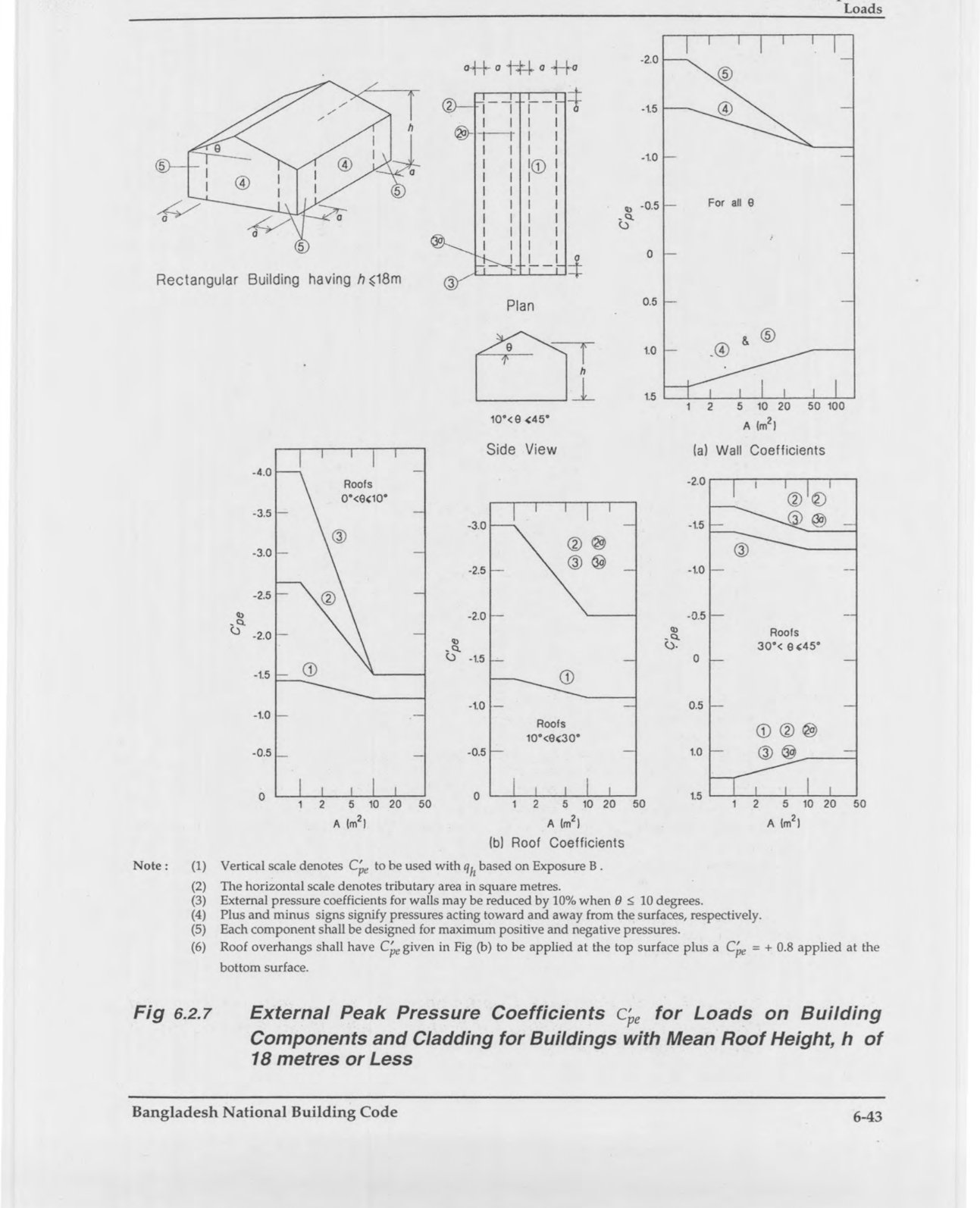
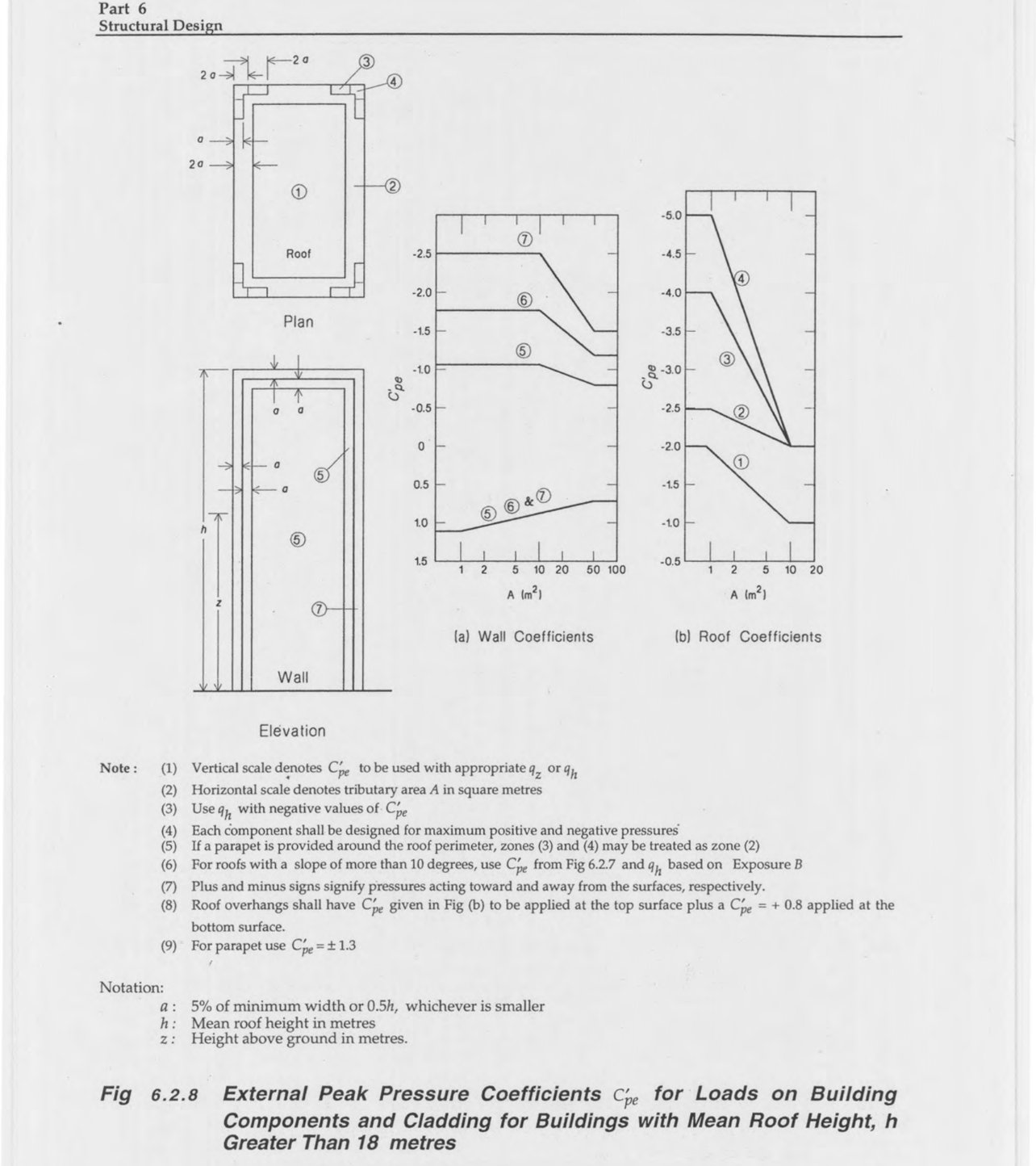
Design wind load on individual structural components such as roofs, walls, and individual cladding units and their immediate supporting members and fixings etc., of enclosed buildings and structures shall be determined in accordance with the following relation: where, = total wind force on a building component perpendicular to the surface, kN = external peak pressure coefficient for components, see Fig 6.2.7 and 6.2.8 for rectangular building = internal peak pressure coefficient as given in Table 6.2.14 = sustained wind pressure acting on external surfaces of a building = wind pressure developed at the interior of the building. The pressures and shall be determined as follows: For m: and For m: for (+ve) values of , and for (-ve) values of for all values of . If the peak pressure coefficients and are not provided in Fig 6.2.7 and 6.2.8 and in Table 6.2.14, the following equation may be used for determining the wind forces on structural components: where, = design wind pressure for components as given in Eq (2.4.2), kN/m² = projected area of the component normal to wind at level, z above ground, in square metres.2.4.6.6 Wind Gust Effects
Wind gusts cause additional loading effects due to turbulence over the sustained wind speed. For slender buildings and structures, this additional loading gets further amplified due to dynamic wind structure interaction effects. A slender or wind-sensitive building shall be one having (i) a height exceeding five times the least horizontal dimension, or (ii) a fundamental natural frequency less than 1.0 Hz. Gust coefficient, as included in Eq (2.4.2) shall account for such additional gust loading effects on non-slender and slender buildings and shall be set equal to the Gust Response Factors, , or as set forth below: a) Gust Response Factor, for Non-slender Buildings and Structures: For the main wind force resisting systems of non-slender buildings and structures, the value of the gust response factor, shall be determined from Table 6.2.11 evaluated at height h above mean ground level of the building or structure. Height h shall be defined as the mean roof level or the top of the parapet, whichever is greater. b) Gust Response Factor, for Building Components: For components and cladding of all buildings and structures, the value of the gust response factor shall be determined from Table 6.2.11 evaluated at the height above the ground, z at which the component or cladding under consideration is located on the structure. Table 6.2.11: Gust Response Factors, and
Note (1): For main wind-force resisting systems, use building or structure height h for z.
Note (2): Linear interpolation is acceptable for intermediate values of z.
c) Gust Response Factor, for Slender Buildings and Structures: Gust response factor, for the primary framing systems of slender buildings and structures shall be calculated by a rational analysis incorporating the dynamic properties of the primary framing system as given by the following relations.
where,
= fundamental natural frequency of the building or structure, Hz
= structural damping coefficient (fraction of critical damping)
= mean roof height or height to parapet, metre
= average horizontal dimension of the building or structure normal to wind, metre
= basic wind speed, km/h
= 0.00656 for building or structure
= 0.00328 for open framework (lattice) structure
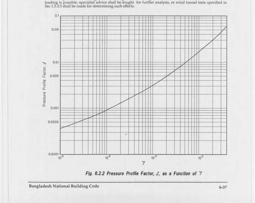
= pressure profile factor given in Fig 6.2.2
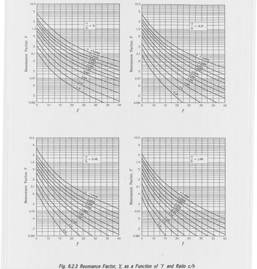
= resonance factor given in Fig 6.2.3
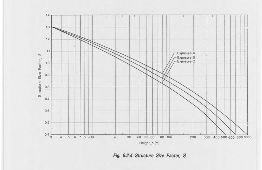
= structure size factor provided in Fig 6.2.4
Other parameters of Eq (2.4.8) through (2.4.11) are defined in Sec 2.4.2. Values of the parameters , , and shall be those given in Table 6.2.12.
The gust response factor as determined by this provision shall account for the load magnification effect caused by the wind gusts in resonance with along-wind oscillations of the structure, but shall not provide allowances for any cross-wind response such as that due to vortex shedding, galloping, flutter and ovalling, nor for any torsional loading effect resulting from such response. Cases where cross-wind or torsional loading is possible, specialist advice shall be sought for further analysis, or wind tunnel tests specified in Sec 1.5.3.5 shall be made for determining such effects.
2.4.6.7 Pressure Coefficients for Buildings, Structures and Components
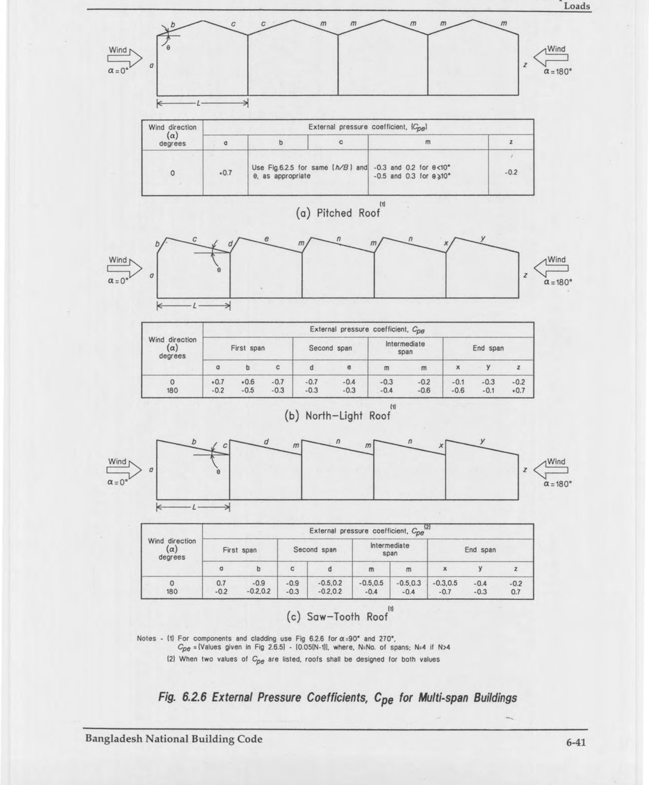
The pressure coefficients to be used in Eq (2.4.2) for the determination of design wind pressure shall be equal to the values described below: a) : external pressure coefficient as given in Fig 6.2.5 and Fig 6.2.6 and in Table 6.2.13 for external surfaces of buildings or structures. This coefficient shall be used with Method 1 given in Sec 2.4.6.4a(i). b) : internal peak pressure coefficients as given in Table 6.2.14 for internal surfaces of buildings. These coefficients shall be used along with the coefficients for design wind load on components, or with for design wind load on buildings as per provisions of Sec 2.4.6.4a(ii). c) : external peak pressure coefficient as given in Fig 6.2.7 and 6.2.8 to be applied on external surfaces of buildings to obtain design wind load on individual components and cladding in accordance with Sec 2.4.6.5. d) : overall pressure coefficient as given in Tables 6.2.15 through 6.2.21 for various cross-sectional shapes to be used with the projected area of buildings or structures when Method 2 in Sec 2.4.6.4(b) is used. If pressure coefficients , , or are not provided herein for certain buildings, structures or components, reliable references shall be followed or specialist advice shall be sought.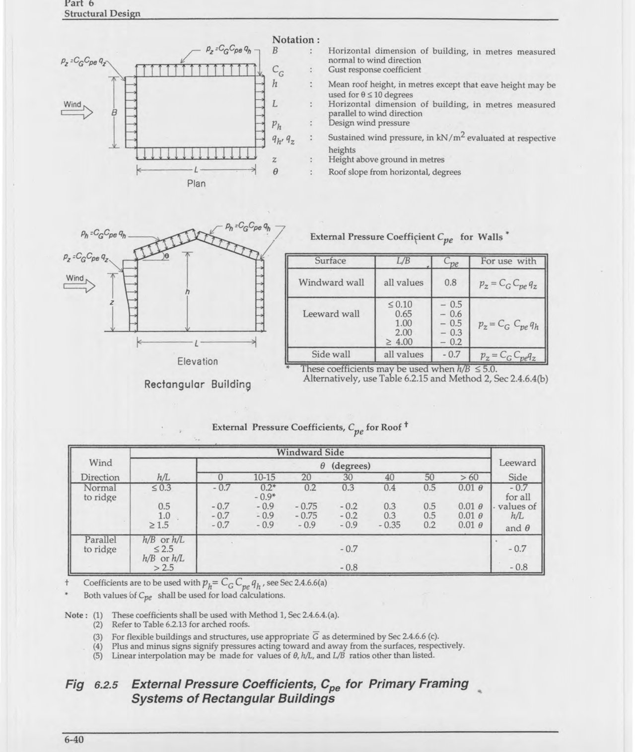
* When the rise-to-span ratio is alternate coefficients given by shall also be used for the windward quarter.
Notes: (1) Values listed are for the determination of average loads on primary framing system. (2) Plus and minus signs signify pressures acting toward and away from the surfaces, respectively. (3) For components and cladding: a) At roof perimeter, use the external pressure coefficients in Fig 6.2.7 with based on spring-line slope and based on Exposure B. b) For remaining roof area, use external pressure coefficients of this table multiplied by 1.2 and based on Exposure B.
Table 6.2.14: Internal Peak Pressure Coefficients for Buildings,
Notes: (1) Values are to be used with or as specified in Sec 2.4.6.4 a(ii) and 2.4.6.5. (2) Plus and minus signs signify pressures acting toward and away from the surfaces, respectively. (3) Appropriate positive and negative values of shall be considered when determining the controlling load requirement. (4) Percentage of openings is based on gross area of wall.
Note: (1) These coefficients are to be used with Method-2 given in Sec 2.4.6.6a(ii). Use for roof in all cases. (2) Linear interpolation may be made for intermediate values of h/B and L/B.
Table 6.2.16: Overall Pressure Coefficient, for Buildings and Structures such as Chimneys, Tanks, etc.
Notes: 1) The design wind force shall be calculated based on the area of the structure projected on a plane normal to the wind direction. The force shall be assumed to act parallel to the wind direction. 2) Linear interpolation may be used for h/D values other than those shown. 3) Notation: D = diameter or least horizontal dimension, metres. D’ = depth of protruding elements such as ribs and spoilers, metres. h = height of structure, metres.
Table 6.2.17: Overall Pressure Coefficients for Monoslope Roofs Over Unenclosed Buildings and Structures
Location of centre of pressure, X/L:
Note: 1) Wind forces act normal to the surface and shall be directed inward or outward. 2) Wind shall be assumed to deviate by ± 10 degrees from horizontal. 3) Notation: B = dimension of roof measured normal to wind direction, metres. L = dimension of roof measured parallel to wind direction, metres. X = distance to centre of pressure from windward edge of roof, metres. = angle of plane of roof from horizontal, degrees.
Table 6.2.18: Overall Pressure Coefficients, for Solid Signs
Note: 1) Signs with openings comprising less than 30% of the gross area shall be considered as solid signs. 2) Signs for which the distance from the ground to the bottom edge is less than 0.25 times the vertical dimension shall be considered to be at ground level. 3) To allow for both normal and oblique wind directions, two cases shall be considered: a) Resultant force acts normal to sign at geometric centre, and b) Resultant force acts normal to sign at level of geometric centre and at a distance from windward edge of 0.3 times the horizontal dimension. 4) Notation: v = ratio of height to width, M = larger dimension of sign, metres, N = smaller dimension of sign, metres.
Table 6.2.19: Overall Pressure Coefficients for Open Signs and Lattice Frameworks
Notes: 1) Signs with openings comprising 30% or more of the gross area are classified as open signs. 2) The calculation of the design wind forces shall be based on the area of all exposed members and elements projected on a plane normal to the wind direction. Forces shall be assumed to act parallel to the wind direction. 3) Notation: = ratio of solid area to gross area, D = diameter of a typical round member, in metres.
Table 6.2.20: Overall Pressure Coefficients, for Trussed Towers
Note: 1) Force coefficients are given for towers with structural angles or similar flat-sided members. 2) For towers with rounded members, the design wind force shall be determined using the values in the above table multiplied by the following factors: For : factor = 0.67. For : factor = . For : factor = 1.0. 3) For triangular section towers, the design wind forces shall be assumed to act normal to a tower face. 4) For square section towers, the design wind forces shall be assumed to act normal to a tower face. To allow for the maximum horizontal wind load, which occurs when the wind is oblique to the faces, the wind load acting normal to a tower face shall be multiplied by the factor for and shall be assumed to act along a diagonal. 5) Wind forces on tower appurtenances, such as ladders, conduits, lights, elevators, and the like, shall be calculated using appropriate force coefficients for these elements. 6) For guyed towers, the cantilever portion of the tower shall be designed for 125% of the design force. 7) A reduction of 25% of the design force in any span between guys shall be made for determination of controlling moments and shears. 8) Notation: = ratio of solid area to gross area of tower face. D = typical member diameter, in metres.
Table 6.2.21: Overall Pressure Coefficients, and for Tower Guys
Notes: 1) The force coefficients shall be used in conjunction with exposed area of the tower guy in square metre, calculated as chord length multiplied by guy diameter. 2) Notation: = force coefficient for the component of force acting in direction of the wind. = force coefficient for the component of force acting normal to direction of the wind and in the plane containing the angle . = angle between wind direction and chord of the guy, in degrees.
2.4.6.8 Effect of Local Topography
If a structure or any portion thereof is located within a local topographic zone, such as regions around hills and ridges as shown in Fig 6.2.9, the sustained wind pressure obtained from Sec 2.4.6.2 shall be modified by multiplying by a local topographic coefficient, . Value of the coefficient, shall be obtained from Fig 6.2.9.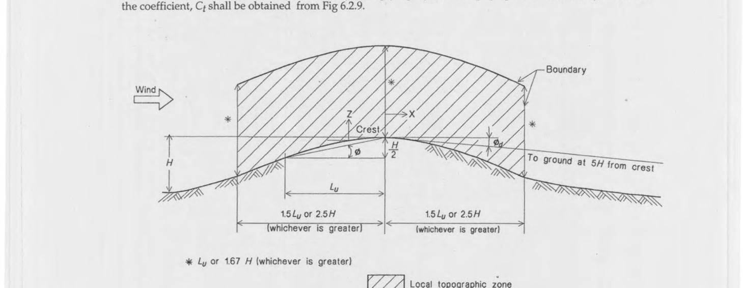
Legend:
= the upwind slope,
= the average downwind slope, measured from the crest of a hill or ridge to the ground level at a distance of 5H.
= the height of the hill or ridge in metres
= the horizontal distance upwind from the crest to a level half the height below the crest in metres.
Notes: (1) For intermediate values of upwind slope, linear interpolation is permitted. (2) for a point at or outside the boundary of the local topographic zones as shown in the figure. For any point within the local topographic zone, value of the coefficient, shall be obtained by interpolation from the value at crest given in the table and the value of at the boundary of the zone. The interpolation shall be linear with horizontal distance from the crest, and with height above the local ground level.
2.5 Earthquake Loads
2.5.1 General
Minimum design earthquake forces for buildings, structures or components thereof shall be determined in accordance with the provisions of this section. For primary framing systems of buildings or structures, the design seismic lateral forces shall be calculated either by the Equivalent Static Force Method or by the Dynamic Response Method based on the criteria set forth in Sec 2.5.5.1. Overall design of buildings and structures to resist seismic ground motion and other forces shall comply with the applicable design requirements given in Chapter 1.2.5.2 Definitions
The following definitions of terms shall be applicable only to the provisions of Sec 2.5: BASE: The level at which the earthquake motions are considered to be imparted to the structures or the level at which the structure as a dynamic vibrator is supported. BASE SHEAR: Total design lateral force or shear at the base of a structure. BEARING WALL SYSTEM: A structural system without a complete vertical load carrying space frame, see Sec 1.3.2. BRACED FRAME: An essentially vertical truss system of the concentric or eccentric type which is provided to resist lateral forces. BUILDING FRAME SYSTEM: An essentially complete space frame which provides support for gravity loads, see Sec 1.3.2. DIAPHRAGM: A horizontal or nearly horizontal system of structures acting to transmit lateral forces to the vertical resisting elements. The term “diaphragm” includes horizontal bracing systems. DUAL SYSTEM: A combination of a Special or Intermediate Moment Resisting Frame and Shear Walls or Braced Frames designed in accordance with the criteria of Sec 1.3.2. ECCENTRIC BRACED FRAME (EBF): A steel braced frame designed in conformance with Sec 1.8. ESSENTIAL FACILITIES: Buildings and structures which are necessary to remain functional during an emergency or a post disaster period. FLEXIBLE DIAPHRAGM: A floor or roof diaphragm shall be considered flexible, for purposes of this provision, when the maximum lateral deformation of the diaphragm is more than two times the average storey drift of the associated storey. This may be determined by comparing the computed midpoint in-plane deflection of the diaphragm under lateral load with the storey drift of adjoining vertical resisting elements under equivalent tributary lateral load. FLEXIBLE ELEMENT OR SYSTEM: An element or system whose deformation under lateral load is significantly larger than adjoining parts of the system. FLEXIBLY SUPPORTED EQUIPMENT: Non-rigid or flexibly supported equipment is a system having a fundamental period, including the equipment, greater than 0.06 second. HORIZONTAL BRACING SYSTEM: A horizontal truss system that serves the same function as a floor or roof diaphragm. INTERMEDIATE MOMENT RESISTING FRAME (IMRF): A concrete or steel frame designed in accordance with Sec 8.3 or 10.5.17 respectively. MOMENT RESISTING FRAME: A frame in which members and joints are capable of resisting forces primarily by flexure. ORDINARY MOMENT RESISTING FRAME (OMRF): A moment resisting frame not meeting special detailing requirements for ductile behaviour. PRIMARY FRAMING SYSTEM: That part of the structural system assigned to resist lateral forces. RIGIDLY SUPPORTED EQUIPMENT: A rigid or rigidly supported equipment is a system having a fundamental period less than or equal to 0.06 second. SHEAR WALL: A wall designed to resist lateral forces parallel to the plane of the wall (sometimes referred to as a vertical diaphragm or a structural wall). SOFT STOREY: Storey in which the lateral stiffness is less than 70 per cent of the stiffness of the storey above. SPACE FRAME: A three-dimensional structural system without bearing walls composed of members interconnected so as to function as a complete self contained unit with or without the aid of horizontal diaphragms or floor bracing systems. SPECIAL MOMENT RESISTING FRAME (SMRF): A moment resisting frame specially detailed to provide ductile behaviour complying with the seismic requirements provided in Chapters 8 and 10 for concrete and steel frames respectively. SPECIAL STRUCTURAL SYSTEM: A structural system not listed in Table 6.2.24. STOREY: The space between floor levels. Storey-x is the storey below level-x. STOREY SHEAR, : The summation of design lateral forces above the storey under consideration. STRENGTH: The usable capacity of an element or a member to resist the load as prescribed in these provisions. STRUCTURE: An assemblage of framing members designed to support gravity loads and resist lateral forces. Structures may be categorized as building and non-building structures as defined in Sec 1.2.2. TOWER: A tall, slim vertical structure. VERTICAL LOAD-CARRYING FRAME: A space frame designed to carry all vertical gravity loads. WEAK STOREY: Storey in which the lateral strength is less than 80 per cent of that of the storey above.2.5.3 Symbols and Notation
The following symbols and notation shall apply to the provisions of this section: = the combined effective area, in square metres of the shear walls in the first storey of the structure. = the effective horizontal cross-sectional area, in square metres of a shear wall in the first storey of the structure. = the torsion amplification factor at level-x. = numerical coefficient specified in Sec 2.5.6.1. = numerical coefficient specified in Sec 2.5.8 and given in Table 6.2.26. = numerical coefficient given in Sec 2.5.6.2. = the length in metres of a shear wall element in the first storey in the direction parallel to the applied forces. = lateral force at level-i for use in Eq (2.5.5). = lateral force applied to level-i, -n, or -x respectively. = lateral forces on an element or component or on equipment supports. = that portion of the base shear V, considered concentrated at the top of the structure in addition to . = force on floor- or roof-diaphragm. = acceleration due to gravity. = height in metres above the base to level i, -n or -x respectively. = structure importance coefficient given in Table 6.2.23. = structure importance coefficient specified in Sec 2.5.8 for structural and non-structural components and equipment. Level-i = the level of the structure referred to by the subscript i, e.g., i = 1 designates the first level above the base. Level-n = the uppermost level in the main portion of the structure. Level-x = the level under consideration e.g., x = 1 designates the first level above the base. = response modification coefficient for structural systems given in Table 6.2.24. = site coefficient for soil characteristics given in Table 6.2.25. = fundamental period of vibration, in seconds, of the structure in the direction under consideration. = the total design lateral force or shear at the base. = the design storey shear in storey x. = the total seismic dead load defined in Sec 2.5.5.2. = that portion of W which is located at or assigned to level -i or -x respectively. = the weight of the diaphragm and the elements tributary thereto at level-x, including applicable portions of other loads defined in Sec 2.5.5.2. = the weight of an element or component. = seismic zone coefficient given in Table 6.2.22. = horizontal displacement at level-i relative to the base due to applied lateral forces, in metre, for use in Eq (2.5.5).2.5.4 Seismic Zoning
2.5.4.1 Seismic Zoning Map
The seismic zoning map of Bangladesh is provided in Fig 6.2.10. Based on the severity of the probable intensity of seismic ground motion and damages, Bangladesh has been divided into three seismic zones, i.e. Zone 1, Zone 2 and Zone 3 as shown in Fig 6.2.10 with Zone 3 being the most severe.2.5.4.2 Selection of Seismic Zone and Zone Coefficient
Seismic zone for a building site shall be determined based on the location of the site on the Seismic Zoning Map provided in Fig 6.2.10. Each building or structure shall be assigned a Seismic Zone Coefficient, Z corresponding to the seismic zone of the site as set forth in Table 6.2.22.2.5.5 Earthquake Forces for Primary Framing Systems
The design earthquake lateral forces on the primary framing systems of every building or structure shall be calculated based on the provisions set forth in this section. The design seismic forces shall be assumed to act nonconcurrently in the direction of each principal axis of the building or the structure, except otherwise required by the provisions of Sec 1.5.4 and 1.7.2.5.5.1 Selection of Lateral Force Method
Seismic lateral forces on primary framing systems shall be determined by using either the Equivalent Static Force Method provided in Sec 2.5.6, or the Dynamic Response Method given in Sec 2.5.7 complying with the restrictions given below: a) The Equivalent Static Force Method of Sec 2.5.6 may be used for the following structures: i) All structures, regular or irregular, in Seismic Zone 1 and in Structure Importance Category IV in Seismic Zone 2, except case b(iv) below. ii) Regular structures under 75 metres in height with lateral force resistance provided by structural systems listed in Table 6.2.24, except case b(iv) below. iii) Irregular structures not more than 20 metres in height. iv) A tower like building or structure having a flexible upper portion supported on a rigid lower portion where:- both portions of the structure considered separately can be classified as regular structures,
- the average storey stiffness of the lower portion is at least ten times the average storey stiffness of the upper portion, and
- the period of the entire structure is not greater than 1.1 times the period of the upper portion considered as a separate structure fixed at the base.
2.5.5.2 Seismic Dead Load
Seismic dead load, W, is the total dead load of a building or a structure, including permanent partitions, and applicable portions of other loads listed below: a) In storage and warehouse occupancies, a minimum of 25 per cent of the floor live load shall be applicable. b) Where an allowance for partition load is included in the floor design in accordance with Sec 2.3.3.3, all such loads but not less than 0.6 kN/m² shall be applicable. c) Total weight of permanent equipment shall be included.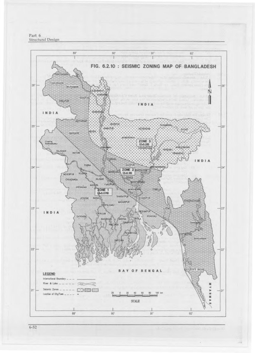
2.5.6 Equivalent Static Force Method
This method may be used for calculation of seismic lateral forces for all structures specified in Sec 2.5.5.1(a).2.5.6.1 Design Base Shear
The total design base shear in a given direction shall be determined from the following relation: where, = Seismic zone coefficient given in Table 6.2.22 = Structure importance coefficient given in Table 6.2.23 = Response modification coefficient for structural systems given in Table 6.2.24 = The total seismic dead load defined in Sec 2.5.5.2 = Numerical coefficient given by the relation: = Site coefficient for soil characteristics as provided in Table 6.2.25 = Fundamental period of vibration in seconds, of the structure for the direction under consideration as determined by the provisions of Sec 2.5.6.2. The value of C need not exceed 2.75 and this value may be used for any structure without regard to soil type or structure period. Except for those requirements where Code prescribed forces are scaled up by 0.375R, the minimum value of the ratio C/R shall be 0.075. Table 6.2.22: Seismic Zone Coefficients, Z
Table 6.2.23: Structure Importance Coefficients I, I’
2.5.6.2 Structure Period
The value of the fundamental period, T of the structure shall be determined from one of the following methods: a) Method A: For all buildings the value of T may be approximated by the following formula: where, = 0.083 for steel moment resisting frames 0.073 for reinforced concrete moment resisting frames, and eccentric braced steel frames 0.049 for all other structural systems = Height in metres above the base to level n. Alternatively, the value of for buildings with concrete or masonry shear walls may be taken as . The value of shall be obtained from the relation: where, = The combined effective area, in square metres, of the shear walls in the first storey of the structure. = The effective horizontal cross-sectional area, in square metres of a shear wall in the first storey of the structure. = The length, in metre of a shear wall element in the first storey in the direction parallel to the applied forces. The value of for use in Eq (2.5.4) shall not exceed 0.9. Table 6.2.24: Response Modification Coefficient for Structural Systems, R
Notes: (1) Basic Structural Systems are defined in Sec 1.3.2, Chapter 1. (2) See Sec 2.5.6.6 for combination of structural systems, and Sec 1.3.5 for system limitations. (3) Prohibited in Seismic Zone 3. (4) Prohibited in Seismic Zone 3 except as permitted in Sec 2.5.9.3. (5) Prohibited in Seismic Zones 2 and 3. Sec 1.7.2.6.
Table 6.2.25: Site Coefficient, S for Seismic Lateral Forces
Note: (1) The site coefficient shall be established from properly substantiated geotechnical data. In locations where the soil properties are not known in sufficient detail to determine the soil profile type, soil profile shall be used. Soil profile need not be assumed unless the building official determines that soil profile may be present at the site, or in the event that soil profile is established by geotechnical data.
b) Method B: The fundamental period T may be calculated using the structural properties and deformational characteristics of the resisting elements in a properly substantiated analysis. This requirement may be satisfied by using the following formula:
The values of represent any lateral force distributed approximately in accordance with the principles of Eq (2.5.6), (2.5.7) and (2.5.8) or any other rational distribution. The elastic deflections, shall be calculated using the applied lateral forces, . The value of T determined from Eq (2.5.5) shall not exceed that calculated using Eq (2.5.3) by more than 40%.
2.5.6.3 Vertical Distribution of Lateral Forces
In the absence of a more rigorous procedure, the total lateral force, which is the base shear V, shall be distributed along the height of the structure in accordance with Eq (2.5.6), (2.5.7) and (2.5.8): where, = Lateral force applied at storey level -i and = Concentrated lateral force considered at the top of the building in addition to the force . The concentrated force, acting at the top of the building shall be determined as follows: The remaining portion of the base shear , shall be distributed over the height of the building, including level-n, according to the relation: At each storey level-x, the force shall be applied over the area of the building in proportion to the mass distribution at that level.2.5.6.4 Horizontal Distribution of Shear
The design storey shear , in any storey x is the sum of the forces and above that storey. shall be distributed to the various elements of the vertical lateral force resisting system in proportion to their rigidities, considering the rigidity of the floor or roof diaphragm. Allowance shall also be made for the increased shear arising due to any horizontal torsional moments as specified in Sec 2.5.6.5.2.5.6.5 Horizontal Torsional Moments
Provision shall be made for the increased shears resulting from horizontal torsion where floor diaphragms are not flexible. The torsional design moment at a given storey shall be the moment resulting from eccentricities between applied design lateral forces at levels above that storey and the vertical resisting elements in that storey plus an accidental torsional moment. The accidental torsional moment in any storey shall be determined assuming the storey mass to be displaced from the calculated centre of mass in each direction a distance equal to 5% of the building dimension at that level perpendicular to the direction of the force under consideration. Where torsional irregularity exists (Plan Irregularity Type I as defined in Table 6.1.4) the effects shall be accounted for by increasing the accidental torsion at each level by an amplification factor, determined from the formula: where, = The maximum displacement at level-x. = The average of the displacements at extreme positions of the building at level-x. The more severe loading for each element shall be considered for design.2.5.6.6 Combination of Structural Systems
When structural systems defined in Sec 1.3.2 are combined to be incorporated into the same structure, the following requirements shall be satisfied: a) Vertical Combinations: The value of the response modification coefficient, R used in the design of any storey for a given direction shall not be greater than that used for the storey above. However, this requirement need not apply to a storey where the dead load above that storey is less than 10 per cent of the total dead weight of the structure. Structures may be designed using the procedures of Sec 2.5.6 under the following conditions: i) The type of structure is designed using the lowest value of R for the lateral force resisting systems used, or ii) The following procedure is used for structures conforming to Sec 2.5.5.1a(iv).- The flexible upper portion, shall be designed as a separate structure, supported laterally by the rigid lower portions using the appropriate value of R.
- The rigid lower portion shall be designed as a separate structure using the appropriate value of R. The reactions from the upper portion shall be increased by the ratio of the R values of the two portions. These factored reactions shall be applied at the top of the rigid lower portion in addition to the forces determined for the lower portion itself.
2.5.7 Dynamic Response Method
The Dynamic Response Method, where used, shall conform to the criteria established in this section. The analysis of the structure shall be based on an established principle of mechanics, using a mathematical model specified in Sec 1.2.6.1(a) and one of the dynamic analysis procedures given in Sec 2.5.7.2 and 2.5.7.3. The mass and mass moments of inertia of various components of a structure, required for the dynamic analysis, shall be calculated based on the seismic dead load specified in Sec 2.5.5.2.2.5.7.1 Ground Motion
The ground motion representation as set out in this section shall, as a minimum, be one having 20% probability of being exceeded in 50 years and may be one of the following: a) Response Spectrum: The response spectrum to be used in the dynamic analysis shall be any one of the following: i) Site Specific Design Spectra: A site specific response spectra shall be developed based on the geologic, tectonic, seismologic, and soil characteristics associated with the specific site. The spectra shall be developed for a damping ratio of 0.05 unless a different value is found to be consistent with the expected structural behaviour at the intensity of vibration established for the site. ii) Normalized Response Spectra: In absence of a site-specific response spectra, the normalized response spectra given in Fig 6.2.11 shall be used in the dynamic analysis procedure given in Sec 2.5.7.2. b) Time History: Ground motion time history developed for the specific site shall be representative of actual earthquake motions for the directions under consideration. Response spectra from time history, either individually or in combination, shall approximate the site-specific design spectra conforming to paragraph a(i) above.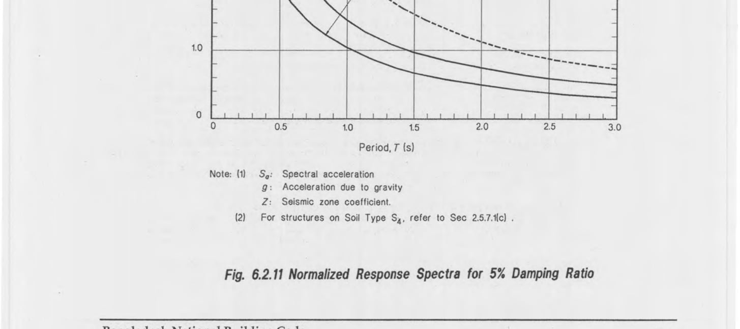
2.5.7.2 Response Spectrum Analysis
Where this procedure is used, an elastic dynamic analysis of a structure shall be performed based on the criteria set forth in this section with a mathematical model conforming to Sec 1.2.6.1(a) and using a response spectrum as specified in Sec 2.5.7.1(a). The analysis shall include the peak dynamic response of all modes having a significant contribution to total structural response. Peak modal response shall be calculated using the ordinates of the appropriate response spectrum curve which correspond to the modal periods. Maximum modal contributions shall be combined in a statistical manner to obtain an approximate total structural response. a) Number of Modes: The requirement that all significant modes be included may be satisfied by demonstrating that, for the modes considered, at least 90 per cent of the participating mass of the structure is included in the calculation of response for each principal horizontal direction. b) Combination of Modes: The peak member forces, displacements, storey forces, storey shears, and base reactions for each mode shall be combined using established procedures in order to estimate resultant maximum values of these response parameters. When three dimensional models are used for analysis, modal interaction effects shall be considered when combining modal maximum. c) Scaling of Results: Where the base shear for a given direction, determined by this procedure, is different from the base shear obtained by using the procedure of Sec 2.5.6.1, it shall be adjusted as follows: i) When the base shear is less than that determined from Sec 2.5.6.1, the following values shall be taken:- The value of the base shear as obtained from Sec 2.5.6.1, for irregular structures.
- 90 per cent of the value from Sec 2.5.6.1 for regular structures except that the base shear shall not be less than 80 per cent of that determined using T from Sec 2.5.6.2(a).
2.5.7.3 Time History Analysis
When this procedure is followed, an elastic or inelastic dynamic analysis of a structure shall be made using a mathematical model of the structure specified in Sec 1.2.6.1(a) and applying at its base or any other appropriate level, a ground motion time history as specified in Sec 2.5.7.1(b). The time-dependent dynamic response of the structure shall be obtained through numerical integration of its equations of motion.2.5.8 Seismic Lateral Forces on Components and Equipment Supported by Structures
2.5.8.1 Lateral Forces on Structural and Non-structural Components, and Equipment
The minimum design seismic lateral forces on elements of structures, non-structural components, equipment and their attachments including anchorage and bracing to the main structural system shall be determined in accordance with the formula: where, = Total lateral seismic force = Seismic zone coefficient as given in Table 6.2.22 = Structure Importance Coefficient for components as given in Table 6.2.23 = Horizontal force Coefficient as specified in Sec 2.5.8.2. = Weight of an element, component or piece of equipment. The total lateral seismic force, obtained from Eq (2.5.10) shall be distributed in proportion to the mass distribution of the element, component or piece of equipment. These forces shall be applied in the horizontal direction to cause the most critical loading for design. Friction resulting from gravity forces shall not be considered to provide resistance to seismic forces. Seismic lateral forces on attachments for floor- or roof-mounted equipment weighing less than 1.8 kN and for furniture need not be determined for design purposes.2.5.8.2 Horizontal Force Coefficient C’
The value of the coefficient shall be determined as follows: a) For elements of structure and non-structural components, and for rigid or rigidly supported equipment supported by structures above grade, shall be taken as those given in Table 6.2.26. b) For non-rigid or flexibly supported equipment supported by a structure and located above grade on a structure, the seismic lateral force shall be determined considering the dynamic properties of both the equipment and those of the structure which supports it, but the value of shall not be less than that listed in Table 6.2.26. In the absence of an analysis or empirical data, the value of shall be taken as twice the value listed in Table 6.2.26 but it need not exceed 2.0. For piping, ducting and conduit systems which are constructed of ductile materials and connections, the values of may be taken as those given in Table 6.2.26. c) The value of for elements, or components and equipment laterally self-supported and located at or below ground level may be two-thirds of the value set forth in Table 6.2.26. However, the design lateral forces obtained from Eq (2.5.10) for these elements shall not be less than that as would be obtained using the provision of Sec 2.5.9.2.5.8.3 Seismic Lateral Forces on Floor or Roof Diaphragms
Seismic lateral forces on floor and roof diaphragms and collector elements shall be determined in accordance with the following formula: a) The force determined from Eq (2.5.11) need not exceed , but it shall not be less than . b) When the diaphragm is required to transfer lateral forces from the vertical resisting elements above the diaphragm to other vertical resisting elements below the diaphragm due to offset in the placement of the elements or to changes in stiffness in the vertical elements, these forces shall be added to those determined from Eq (2.5.11).2.5.9 Seismic Lateral Forces on Non-Building Structures
Non-building structures shall include all self-supporting structures other than buildings that carry gravity loads and resist the effects of earthquake and other lateral forces. Determination of seismic lateral forces for such structures shall be based on the following provisions:2.5.9.1 Seismic Dead Load
For non-building structures, the seismic dead load, W shall include all loads defined for buildings in Sec 2.5.5.2. In addition, W shall include all normal operating contents for structures such as tanks, vessels, bins and piping.2.5.9.2 Fundamental Period
For structures with primary framing systems similar to buildings, the fundamental period T, shall be determined in accordance with Sec 2.5.6.2. For other structures, T shall be obtained by using a rational method such as Method B of Sec 2.5.6.2.2.5.9.3 Structures Similar to Buildings
The seismic lateral forces on structures with primary framing systems similar to buildings (i.e. structural systems listed in Table 6.2.24) shall be determined in accordance with the provisions of Sec 2.5.5 through 2.5.8 with following modifications: a) Intermediate moment resisting frames (IMRF) may be used in structures within Seismic Zone 3 and in structure importance categories III through V, if, (i) the structure is less than 15 m in height, and (ii) is used in load calculations. b) Seismic dead load and structure period shall be calculated in accordance with Sec 2.5.5.2 and 2.5.9.2 respectively. Table 6.2.26: Horizontal Force Coefficient, C’ for Elements, Components and Equipment
Notes: (1) See Sec 2.5.8.2 for items supported at or below grade. (2) See Sec 1.7.2.3 and 2.5.8.2. (3) Where flexible diaphragms provide lateral support for walls and partitions, the value of C’ for anchorage shall be increased 50 per cent for the centre one-half of the diaphragm span. (4) Applies to Seismic Zones 2 and 3 only. (5) See Sec 1.7.2.9 and 2.5.8.3. (6) Ceiling weight shall include all light fixtures and other equipment or partitions which are laterally supported by the ceiling. For the purpose of determining the seismic force, a ceiling weight of not less than 0.2 kN/m² shall be used. Ceilings constructed of lath and plaster or gypsum board, screw or nail attached to suspended members that support a ceiling at one level extending from wall to wall need not be analysed provided the walls are not over 15 m apart. (7) W’ for access floor systems shall be the dead load of the access floor systems plus 25 per cent of the floor live load plus a 0.5 kN/m² partition load allowance. (8) Equipment includes, but is not limited to, boilers, chillers, heat exchangers, pumps, air-handling units, cooling towers, control panels, motors, switchgear, transformers and life-safety equipment. It also includes major conduit, ducting and piping serving such equipment and fire sprinkler systems. See Sec 2.5.8.2 for additional requirements for determining C’ for non-rigid or flexibly mounted equipment.
2.5.9.4 Rigid Structures
For rigid structures (i.e. those with period, T < 0.06 second) including their anchorage, the total lateral force, V shall be determined in accordance with the relation:2.5.9.5 Flat-bottom Tanks at or Below Grade
Seismic forces for flat-bottom tanks or other tanks with supported bottoms, founded at or below grade, shall be calculated using the procedure of Sec 2.5.9.4 considering the entire weight of the tank and its contents. Alternatively, such forces may be determined using one of the following methods. a) A response spectrum analysis, which includes consideration of the actual ground motion anticipated at the site and the inertial effects of the contained fluid. b) A substantiated analysis prescribed for the particular type of tank provided that the seismic zones and Structure Importance Categories are in conformance with Fig 6.2.10 and Sec 1.2.3 respectively.2.5.9.6 Other Structures
For structures (other than buildings), which are not covered by Sec 2.5.9.3 through 2.5.9.5, the minimum seismic lateral forces shall be determined in accordance with the following provisions: a) The total lateral seismic force, V shall be determined using the provisions of Sec 2.5.6 with the coefficient R taken from Table 6.2.27. However, the ratio C/R shall not be less than 0.5. Table 6.2.27: Coefficient, R for Non-Building Structures
b) The vertical distribution of the total lateral seismic force, V, may be determined by one of the following procedures:
- Using provisions of Sec 2.5.6.3.
- Using procedures of Sec 2.5.7.
2.6 Miscellaneous Loads
2.6.1 General
The procedures and limitations for the determination of selected miscellaneous loads are provided in this section. Loads that are not specified in this section or elsewhere in this chapter, may be determined based on information from reliable references or specialist advice may be sought.2.6.2 Definitions
The following definitions and notation shall apply to the provisions of this section only. ESSENTIAL FACILITIES: Buildings and structures which are necessary to remain functional during an emergency or a post disaster period. RATIONAL ANALYSIS: An analysis based on established methods or theories using mathematical formulae and actual or appropriately assumed data. SITE-SPECIFIC DATA: Data obtained either from measurements taken at a site or from substantiated field information required specifically for the structure concerned.2.6.3 Rain Loads
Rain loads shall be determined in accordance with the following provisions.2.6.3.1 Blocked Drains
Each portion of a roof shall be designed to sustain the load from all rainwater that could be accumulated on it if the primary drainage system for that portion is undersized or blocked. Ponding instability shall be considered in this situation.2.6.3.2 Controlled Drainage
Roofs equipped with controlled drainage provisions shall be designed to sustain all rainwater loads on them to the elevation of the secondary drainage system plus 0.25 kN/m². Ponding instability shall be considered in this situation.2.6.4 Loads Due to Flood and Surge
For the determination of flood and surge loads on a structural member, consideration shall be given to both hydrostatic and hydrodynamic effects. Required loading shall be determined in accordance with the established principles of mechanics based on site specific criteria and in compliance with the following provisions of this section. For essential facilities like cyclone and flood shelters and for hazardous facilities specified in Table 6.1.1, values of maximum flood elevation, surge height, wind velocities etc., required for the determination of flood and surge load, shall be taken corresponding to 100-year return period. For structures other than essential and hazardous facilities, these values, shall be based on 50-year return period.2.6.4.1 Flood Loads on Structures at Inland Areas
For structures sited at inland areas subject to flood, loads due to flood shall be determined considering hydrostatic effects which shall be calculated based on the flood elevation of 50-year return period. For river-side structures such as that under Exposure C specified in Sec 2.4.4.1, hydrodynamic forces, arising due to approaching wind-generated waves shall also be determined in addition to the hydrostatic load on them. In this case, the amplitude of such wind-induced water waves shall be obtained from site-specific data.2.6.4.2 Flood and Surge Loads on Structures at Coastal Areas
For structures sited at coastal areas, the hydrostatic and hydrodynamic loads shall be determined as follows: a) Hydrostatic Loads: The hydrostatic loads on structural elements and foundations shall be determined based on the maximum static height of water, , produced by floods or surges as given by the relation: where, and (2.6.2) = Maximum surge height as specified in a(i) below. = Elevation of the extreme surface water level corresponding to a T-year return period specified in (ii) below, metres = Elevation of ground level at site, metres. i) Maximum Surge Height, : The maximum surge height, , associated with cyclones, shall be that corresponding to a 50-year or a 100-year return period as may be applicable, based on site specific analysis. In the absence of a more rigorous site specific analysis, the following relation may be used: where, = design surge height corresponding to a return period of T-years at sea coast, in metres, given in Table 6.2.28. = distance of the structure site measured from the spring tide high-water limit on the sea coast, in km; , if . = rate of decrease in surge height in m/km; the value of may be taken as 1/2 for Chittagong-Cox’s Bazar-Teknaf coast and as 1/3 for other coastal areas. ii) Extreme Surface Water Level, : The elevation of the extreme surface water level, for a site, which may not be associated with a cyclonic storm surge, shall be that obtained from a site specific analysis corresponding to a 50-year or a 100-year return period. Values of are given in Table 6.2.29 for selected coastal locations which may be used in the absence of any site specific data. b) Hydrodynamic Loads: The hydrodynamic load applied on a structural element due to wind-induced local waves of water, shall be determined by a rational analysis using an established method and based on site specific data. In the absence of a site-specific data the amplitude of the local wave, to be used in the rational analysis, shall be taken as m, where, is given in Sec 2.6.4.2(a). Such forces shall be calculated based on 50-year or 100-year return period of flood or surge. The corresponding wind velocities shall be 260 km/h or 289 km/h respectively.2.6.4.3 Breakaway Walls
When non-structural walls, partitions or other non-structural elements located below the maximum flood or surge elevation, are required to break away under high tides or wave action, such non-structural elements shall be designed to sustain a maximum uniformly distributed load of 1.0 kN/m² but not less than 0.5 kN/m² applied on a vertical projection of the area.2.6.5 Temperature Effects
Temperature effects, if significant, shall be considered in the design of structures or components thereof in accordance with the provision of this section. In determining the temperature effects on a structure, the following provisions shall be considered: a) The temperatures indicated, shall be the air temperature in the shade. The range of the variation in temperature for a building site shall be taken into consideration. b) Effects of the variation of temperature within the material of a structural element shall be accounted for by one of the following methods. i) relieve the stresses by providing adequate numbers of expansion or contraction joints, ii) design the structural element to sustain additional stresses due to temperature effects. Table 6.2.28: Design Surge Heights at the Sea Coast, *
Values prepared from information obtained from Annex-D3, MCSP.
Note: (1) These values may be used in the absence of site specific data for structures other than essential facilities listed in Table 6.1.1. (2) These values may be used in the absence of site specific data for essential facilities listed in Table 6.1.1.
Table 6.2.29: Extreme Surface Water Levels During Monsoon at Selected Locations of the Coastal Area above PWD Datum, *
Values prepared from information obtained from Annex-D3, MCSP
Note: (1) These values may be used in the absence of site specific data for structures in Structure Importance Categories III, IV and V listed in Table 6.1.1. (2) These values may be used in the absence of site specific data for structures in Structure Importance Categories I and II listed in Table 6.1.1.
c) when the method b(ii) above is considered to be applicable, the structural analysis shall take into account the following:
i) the variation in temperature within the material of the structural element, exposure condition of the element and the rate at which the material absorb or radiate heat.
ii) the warping or any other distortion caused due to temperature changes and temperature gradient in the structural element.
d) When it can be demonstrated by established principle of mechanics or by any other means that neglecting some or all of the effects of temperature, does not affect the safety and serviceability of the structure, the temperature effect can be considered insignificant and need not be considered in design.
2.6.6 Soil and Hydrostatic Pressure
For structures or portions thereof, lying below ground level, loads due to soil and hydrostatic pressure shall be determined in accordance with the provisions of this section and applied in addition to all other applicable loads.2.6.6.1 Pressure on Basement Wall
In the design of basement walls and similar vertical or nearly vertical structures below grade, provision shall be made for the lateral pressure of adjacent soil. Allowance shall be made for possible surcharge due to fixed or moving loads. When a portion or the whole of the adjacent soil is below the surrounding water table, computations shall be based on the submerged unit weight of soil, plus full hydrostatic pressure.2.6.6.2 Uplift on Floors
In the design of basement floors and similar horizontal or nearly horizontal construction below grade, the upward pressure of water, if any, shall be taken as the full hydrostatic pressure applied over the entire area. The hydrostatic head shall be measured from the underside of the construction.2.6.7 Loads Due to Explosions
Loads on buildings or portions thereof, shall be assessed in accordance with the provisions of this section.2.6.7.1 Explosion Effects in Closed Rooms
a) Determination of Loads and Response: Internal overpressure developed from an internal explosion such as that due to leaks in gas pipes, evaporation of volatile liquids, internal dust explosion etc., in rooms of sizes comparable to residential rooms and with ventilation areas consisting of window glass breaking at a pressure of 4 kN/m² (3-4 mm machine made glass) may be calculated from the following method: i) The overpressure, provided in Fig 6.2.12(a) shall be assumed to depend on a factor , where, is the total window area in m² and is the volume in m³ of the room considered, ii) The internal pressure shall be assumed to act simultaneously upon all walls and floors in one closed room, and iii) The action obtained from Fig 6.2.12(a) may be taken as static action. When a time dependent response is required, an impulsive force function similar to that shown in Fig 6.2.12(b) shall be used in a dynamic analysis, where is the time from the start of combustion until maximum pressure is reached and is the time from maximum pressure to the end of combustion. For and the most unfavourable values shall be chosen in relation to the dynamic properties of the structures. However, the values shall be chosen within the intervals as given in Fig 6.2.12(b). The pressure may be applied solely in one room or in more than one room at the same time. In the latter case, all rooms are incorporated in the volume . Only windows or other similarly weak and light weight structural elements may be taken as ventilation areas even though certain limited structural parts break at pressures less than .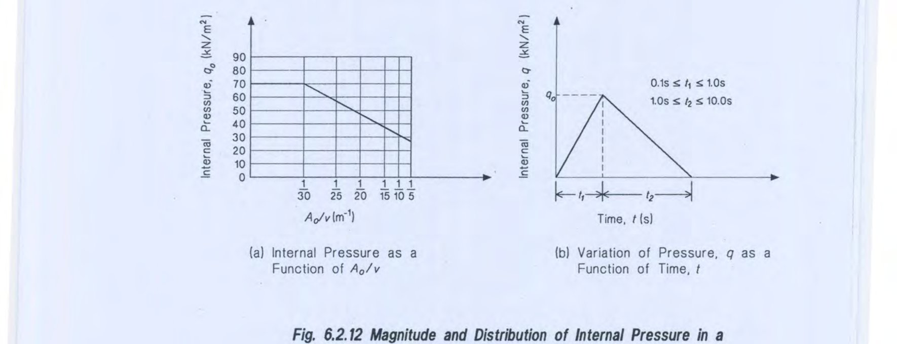
2.6.7.2 Minimum Design Pressure
Walls, floors and roofs and their supporting members separating a use from an explosion exposure, shall be designed to sustain the anticipated maximum load effects resulting from such use including any dynamic effects, but for a minimum internal pressure or suction of 5 kN/m², in addition to all other loads specified in this chapter.2.6.7.3 Design Pressure on Relief Vents
When pressure-relief vents are used, such vents shall be designed to relieve at a maximum internal pressure of 1.0 kN/m².2.6.7.4 Loads Due to Other Explosions
Loads arising from other types of explosions, such as those from external gas cloud explosions, external explosions due to high explosives (TNT) etc. shall be determined, for specific cases, by rational analyses based on information from reliable references or specialist advice shall be sought.2.6.8 Vertical Forces on Air Raid Shelters
For the design of air raid shelters located in a building e.g. in the basement below ground level, the characteristic vertical load shall be determined in accordance with provisions of Sec 2.6.8.1 below.2.6.8.1 Characteristic Vertical Loads
Buildings in which the individual floors are acted upon by a total distributed live load of up to 5.0 kN/m², vertical forces on air raid shelters generally located below ground level, such as a basement, shall be considered to have the characteristic values provided in Table 6.2.30. In the case of buildings having floors that are acted upon by a live load larger than 5.0 kN/m², above values shall be increased by the difference between the average live loads on all storeys above the one used as the shelter and 5.0 kN/m². Table 6.2.30: Characteristic Vertical Loads for an Air Raid Shelter in a Building
Note: (1) Storeys shall mean every usable storey above the shelter floor. (2) Buildings of particularly stable construction shall mean buildings having bearing structural elements made from reinforced in-situ concrete.
2.6.9 Loads on Helicopter Landing Areas
In addition to all other applicable loads provided in this chapter, including the dead load, the minimum live load on helicopter landing or touch down areas shall be one of the loads , or as given below producing the most unfavourable effect: i) (2.6.4a) ii) (2.6.4b) iii) (2.6.4c) where, = Actual weight of the helicopter in kN, = Fully loaded weight of the helicopter in kN, = A distributed load of 5.0 kN/m², = 0.75 for helicopters equipped with hydraulic-type shock absorbers, and 1.5 for helicopters with rigid or skid-type landing gear. The live load, shall be applied over the actual areas of contact of landing. The load, shall be a single concentrated load including impact applied over a 300 mm x 300 mm area. The loads and may be applied anywhere within the landing area to produce the most unfavourable effects of load.2.6.10 Erection and Construction Loads
All loads required to be sustained by a structure or any portion thereof due to placing or storage of construction materials and erection equipment including those due to operation of such equipment shall be considered as erection loads. Provisions shall be made in design to account for all stresses due to such loads.2.7 Combinations of Loads
2.7.1 General
Buildings, foundations and structural members shall be investigated for adequate strength to resist the most unfavourable effect resulting from the various combinations of loads provided in this section. The combination of loads may be selected using the provisions of either Sec 2.7.4 or 2.7.5 whichever is applicable. However, once Sec 2.7.4 or 2.7.5 is selected for a particular construction material, it must be used exclusively for proportioning elements of that material throughout the structure. In addition to the load combinations given in Sec 2.7.4 and 2.7.5 any other specific load combination provided elsewhere in this Code shall also be investigated to determine the most unfavourable effect. The most unfavourable effect of loads may also occur when one or more of the contributing loads are absent, or act in the reverse direction. Loads such as , or shall be considered in design when their effects are significant. Floor live loads shall not be considered where their inclusion result in lower stresses in the member under consideration. The most unfavourable effects from both wind and earthquake loads shall be considered where appropriate, but they need not be assumed to act simultaneously.2.7.2 Definitions
ALLOWABLE STRESS DESIGN METHOD (ASD): A method for proportioning structural members such that the maximum stresses due to service loads obtained from an elastic analysis does not exceed a specified allowable value. This is also called Working Stress Design Method (WSD). DESIGN STRENGTH: The product of the nominal strength and a resistance factor. FACTORED LOAD: The product of the nominal load and a load factor. LIMIT STATE: A condition in which a structure or component becomes unfit for service and is judged either to be no longer useful for its intended function (serviceability limit state) or to be unsafe (strength limit state). LOAD EFFECTS: Forces, moments, deformations and other effects produced in structural members and components by the applied loads. LOAD FACTOR: A factor that accounts for unavoidable deviations of the actual load from the nominal value and for uncertainties in the analysis that transforms the load into a load effect. LOADS: Forces or other actions that arise on structural systems from the weight of all permanent constructions, occupants and their possessions, environmental effects, differential settlement, and restrained dimensional changes. Permanent loads are those loads in which variations in time are rare or of small magnitude. All other loads are variable loads. NOMINAL LOADS: The magnitudes of the loads such as dead, live, wind, earthquake etc. specified in Sec 2.2 through 2.6 of this chapter. NOMINAL STRENGTH: The capacity of a structure or component to resist the effects of loads, as determined by computations using specified material strengths and dimensions and formulas derived from accepted principles of structural mechanics or by field tests or laboratory tests of scaled models, allowing for modelling effects and differences between laboratory and field conditions. RESISTANCE FACTOR: A factor that accounts for unavoidable deviations of the actual strength from the nominal value and the manner and consequences of failure. This is also known as strength reduction factor. STRENGTH DESIGN METHOD: A method of proportioning structural members using load factors and resistance factors satisfying both the applicable limit state conditions. This is also known as Load Factor Design Method (LFD) or Ultimate Strength Design Method (USD). WORKING STRESS DESIGN METHOD (WSD): See ALLOWABLE STRESS DESIGN METHOD.2.7.3 Symbols and Notation
= dead load consisting of: a) weight of the member itself, b) weight of all materials of construction incorporated into the building to be permanently supported by the member, including built-in partitions, c) weight of permanent equipment. = earthquake load = amplified earthquake load equal to = loads due to fluids with well-defined pressures and maximum heights, including loads due to water pressure during flood and surge. = loads due to weight and lateral pressure of soil and water in soil = + ( or ) = live loads due to intended use and occupancy, including loads due to movable objects and movable partitions and loads temporarily supported by the structure during maintenance. includes any permissible reduction. If resistance to impact loads is taken into account in design, such effects shall be included with the live loads . = roof live loads = loads due to initial rainwater ponding = seismic coefficient defined in Sec 2.5.3 = self-straining forces and effects arising from contraction or expansion resulting from temperature changes, shrinkage, moisture changes, creep in component materials, movement due to differential settlement, or combinations thereof. = wind load2.7.4 Combinations of Loads and Stress Increase for Allowable Stress Design Method
2.7.4.1 Combination of Loads
Provisions of this section shall apply to all construction materials permitting their use in proportioning structural members by allowable stress design method. When this method is used in designing structural members, all loads listed herein shall be considered to act in the following combinations. The combination that produces the most unfavourable effect shall be used in design.2.7.4.2 Stress Increase
Except as specified in Sec 1.5.5.(b) and elsewhere in this Code, the maximum permissible increase in the allowable stresses of all materials and soil bearing capacities specified in this Code for working (or allowable) stress design method, when load combinations (7) through (11) in Sec 2.7.4.1 above is used, shall be 33%.2.7.5 Combinations of Loads for Strength Design Method
When strength design method is used, structural members and foundations shall be designed to have strength not less than that required to resist the most unfavorable effect of the combinations of factored loads listed in the following sections:2.7.5.1 Load Combinations for Reinforced Concrete and Masonry Structures
2.7.5.2 Load Combinations for Steel Structures
2.7.5.3 Load Combinations for Design using Other Materials
When structural members are designed using the strength design method and using a construction material not covered in Sec 2.7.5.1 and 2.7.5.2, any other code or standard having load combinations applicable for that construction material may be used provided that other requirements of Sec 2.7 are satisfied.Related AppendixAppendix A — Conversion of Expressions from SI to FPS Units