
6.1 PURPOSE AND SCOPE
6.1.1
The purpose of this chapter of the Code is to provide minimum standards for the design, installation and maintenance of water supply and distribution system within a building and its premises.6.1.2
The regulations of this chapter also provide guidelines for water requirements for different classes of buildings according to their occupancy classification.6.1.3
The provisions stated herein do not cover the requirements of water supply for industrial plants and process, municipal uses, viz. street washing, street hydrant, etc.6.2 TERMINOLOGY
This section provides an alphabetical list of the terms used in and applicable to this chapter of the Code. In case of any conflict or contradiction between a definition given in this section and that in Part 1, the meaning provided in this section shall govern for interpretation of the provisions of this chapter. ACCESSIBLE : When applied to a fixture, appliance or equipment shall mean having access thereto, but which may require the removal of an access panel or similar obstruction; “readily accessible” shall mean direct access without the necessity of removing any panel, door or similar obstruction. AIR GAP : The unobstructed vertical distance through the free atmosphere between the lowest opening of any pipe or faucet supplying water to tank, plumbing fixture or other device and the flood level rim of the receptacle. AVAILABLE HEAD : The head of water available at the point of consideration due to mains’ pressure or storage tank or any other source of pressure. BACK SIPHONAGE : The flowing back of used, contaminated, or polluted water from a plumbing fixture or vessel into a water supply pipe due to a reduced pressure in such a pipe (see BACKFLOW). BACKFLOW : The flow of water or other liquids, mixtures or substances into the distribution pipes of a potable water supply from any source other than its intended source. BACKFLOW CONNECTION OR CONDITION : Any arrangement whereby backflow can occur. BACKFLOW PREVENTOR : A device or means to prevent backflow. BALL COCK : A water supply valve, opened or closed by means of a float or similar device, used to supply water to a tank forming an approved air gap or vacuum breaker and acting as an antisiphon device. Also known as FLOAT OPERATED VALVE. BEDPAN WASHER AND STERILIZER : A fixture designed to wash bedpans and to flush the contents into the sanitary drainage system and located adjacent to a water closet or clinical sink. Such fixtures can also be provided for disinfecting utensils by scalding with steam or hot water. BRANCH : Any part of the piping system other than a riser or main. BRANCH CONNECTOR : A connector between water main and branch pipes by T, Y, T-Y, double Y, and V branches according to their respective shapes. BUILDING SUPPLY : The water supply pipe carrying potable water from the water meter or other source of water supply to a building or other point of use or distribution on the lot. CONTAMINATION : A general term meaning the introduction into the potable water supply of chemicals, wastes or sewage which will render the water unfit for its intended purpose. CRITICAL LEVEL : The level at which the vacuum breaker may be submerged before backflow occurs. When the critical level is not indicated on the vacuum breaker, the bottom of the device shall be considered. CROSS-CONNECTION : Any physical connection or arrangement between two otherwise separate piping systems, one of which contains potable water and the other either water of unknown or questionable safety or steam, gas, or chemical whereby there may be a flow from one system to the other, the direction of flow depending on the pressure differential between the two systems (See BACKFLOW). CYLINDER : A cylindrical closed vessel capable of containing water under pressure greater than the atmospheric pressure. DEVELOPED LENGTH : Length of a pipe along the centreline of the pipe and fittings DISTRIBUTION PIPE : Any pipe conveying water from a storage tank / cistern or from a hot water apparatus supplied from a feed cistern under pressure from that cistern. EFFECTIVE OPENING : The minimum cross-sectional area at the point of water supply discharge measured or expressed in terms of - (1) diameter of a circle, (2) if the opening is not circular, the diameter of a circle of equivalent cross-sectional area. (This is also applicable to AIR GAP.) FAUCET : A valve end of a water pipe by means of which water can be drawn from or held within the pipe. FEED CISTERN : A storage tank / cistern used for supplying cold water to a hot water apparatus. FITTING : Anything fitted or fixed in connection with the supply, measurement, control, distribution, utilization or disposal of water. “Water fitting” includes pipes (other than mains), taps, cocks, valves, ferrules, meters, cisterns, baths, water closets, soil pans and other similar apparatus used in connection with the supply and use of water. FIXTURE : See PLUMBING FIXTURE. FIXTURE BRANCH : A water supply pipe between the fixture supply pipe and the water distribution pipe. FIXTURE SUPPLY : A water supply pipe connecting the fixture with the fixture branch. FIXTURE UNIT : A quantity in terms of which the load producing effects on the plumbing system of different kinds of plumbing fixtures are expressed on some arbitrary chosen scale. FLOAT OPERATED VALVE : See BALL COCK. FLOOD LEVEL RIM : The top edge of a receptacle from which water overflows. FLUSH TANK : A tank located above water closets, urinals or similar fixtures for the purpose of flushing the usable portion of the fixture. Also known as FLUSHING CISTERN and FLUSHOMETER TANK. FLUSH VALVE : See FLUSHOMETER VALVE. FLUSHING CISTERN : See FLUSH TANK. FLUSHOMETER TANK : See FLUSH TANK. FLUSHOMETER VALVE : A device located at the bottom of the tank, and which discharges a predetermined quantity of water to fixtures for flushing purposes and is closed by direct water pressure or other mechanical means. Also known as FLUSH VALVE. FULL FACILITIES : The modern plumbing facilities allowed to the occupants of modern dwellings or, of VIP hotels and accommodations. FULL OPEN VALVE : A shutoff valve that in the full position has a straight through flow passageway with a diameter not less than one nominal pipe size smaller than nominal pipe size of the connecting pipe. GEYSER : An apparatus for heating water with supply control on the inlet side and delivering it from an outlet. GRADE : The slope or fall of a line of pipe with reference to a horizontal plane. HANGERS : See SUPPORTS. HORIZONTAL PIPE : Any pipe or fitting which is installed in a horizontal position or which makes an angle less than 45 degrees with the horizontal . HOT WATER TANK : A vessel for storing hot water under pressure greater than the atmospheric pressure. INDIVIDUAL WATER SUPPLY : A supply other than an approved public water supply which serves one or more families. LAGGING : The material used for thermal or acoustic insulation. LIQUID WASTE : The discharge from any fixture, appliance or appurtenance in connection with a plumbing system which does not receive faecal matter. MAIN : The principal artery of the system, to which branches may be connected, for the purpose of water supply from a supply to individual consumers. Also known as WATER MAIN. MECHANICAL JOINT : A connection between pipes, fittings or pipes and fittings which is neither screwed, caulked, threaded, soldered, solvent cemented, brazed nor welded. OFFSET : A combination of approved bends in a line of piping used to connect two pipes whose axes are parallel but not in line. PLUMBING : The business, trade or work having to do with the installation, removal, alteration or repair of plumbing and drainage systems or part thereof. PLUMBING APPLIANCES : The plumbing fixtures whose operation or control can be dependent upon one or more energized components, such as motors, controls, heating elements, or pressure sensing elements. PLUMBING APPURTENANCE : A manufactured device or prefabricated assembly of component parts, which is an adjunct to the basic piping system and plumbing fixtures, performing some useful function in the operation, maintenance, servicing, economy or safety of the plumbing system. PLUMBING FIXTURE : A receptacle or device which is either permanently or temporarily connected to the water distribution system of the premises, and demands a supply of water therefrom, or discharges used water, waste materials or sewage either directly or indirectly to the drainage system of the premises, or requires both a water supply connection and a discharge to the drainage system of the premises. Also known as PLUMBING FIXTURE. PLUMBING SYSTEM : A system of potable water supply and distribution pipes, plumbing fixtures and traps, soil waste and vent pipes, sanitary and storm sewers and building drains including their respective connections, devices and appurtenances within a building or premises. POTABLE WATER : Water free from impurities which may cause diseases or harmful physiological effects and water which is satisfactory for drinking, culinary and domestic purposes. PRIVATE/PRIVATE USE : Plumbing fixtures intended for the use of a family in residences, or for the restricted use of an individual in commercial establishments. QUICK CLOSING VALVE : A valve or faucet that closes automatically when released manually or controlled by mechanical means for fast action closing. RECEPTOR : An approved plumbing fixture or device of such material, shape and capacity as to adequately receive the discharge from indirect waste pipes, so constructed and located as to be readily cleaned. RESIDUAL HEAD : The head available at any particular point in the distribution system. RESTRICTED FACILITIES : The minimum plumbing facilities acceptable for the occupants of low income group. RIM : An unobstructed open edge of a fixture. RISER : A water supply pipe which extends vertically one full storey or more to convey water to branches or fixtures. ROUGHING-IN : The installation of all parts of the plumbing system which can be completed prior to the installation of fixtures. This includes water supply, drainage, vent piping and necessary supports. SERVICE PIPE : The pipe that runs between the distribution main in the street and the riser in case of a multi-storied building or the water meter in the case of an individual house and is subject to water pressure from such main. SLIP JOINT : An adjustable tubing connection, consisting of a compression nut, a friction ring, and a compression washer, designed to fit a threaded adapter fitting, or a standard taper pipe thread. SOLDERED JOINT : A joint obtained by the joining of metal parts with metallic mixtures of alloys which melt at a temperature below 427°C and above 149°C. STOP VALVE : Any device (including a stopcock or stop tap) other than a draw off tap, for stopping at will the flow of water in a pipe. STORAGE CISTERN : A container, other than a flashing cistern, having a free water surface under atmospheric pressure and used for storage of water, and is connected to the water main or tube-well by means of supply pipe. Also known as STORAGE TANK. STORAGE TANK : See STORAGE CISTERN. SUPPORTS : Hangers and anchors or devices for supporting and securing pipe, fixture and equipment to walls, ceilings, floors or other structural members. Also known as HANGERS. TEMPERED WATER : The water ranging in temperature from 29°C up to 43°C. VACUUM BREAKER : A type of backflow preventor installed on openings subject to normal atmospheric pressure. VERTICAL PIPE : Any pipe which is installed in a vertical position or which makes an angle of not more than 45 degrees with the vertical. WARNING PIPE : An overflow pipe so fixed that its outlet whether inside or outside a building, is in a conspicuous position where the discharge of any water therefrom can be readily seen. WASHOUT VALVE : A device located at the bottom of the tank for the purpose of draining a tank for cleaning, maintenance, etc. WATER CONDITIONING OR TREATING DEVICE : A device which conditions or treats a water supply so as to change its chemical content or remove suspended solids by filtration. WATER HAMMER ARRESTER : A device used to absorb the pressure surge (water hammer) which occurs when water flow is suddenly stopped in a water supply system. WATER HEATER : Any heating device that heats potable water and supplies it to the potable hot water distribution system. WATER LINE : A line marked inside a cistern to indicate the highest water level at which the ball valve should be adjusted to shut off. WATER MAIN : See MAIN. WATER OUTLET : A discharge opening through which water is supplied to a fixture, into the atmosphere (except into an open tank which is part of the water supply system), to a boiler or heating system, or to any devices or equipment requiring water to operate but which are not part of the plumbing system. WATER SUPPLY SYSTEM : A system consisting of building supply pipe, water distributing pipes, and necessary connecting pipes, fittings, control valves, and all appurtenances carrying or supplying potable water in or adjacent to the building or premises. WELDED JOINTS OR SEAM : Any joint or seam obtained by the joining of metal parts in the plastic molten state.6.3 PERMIT FOR WATER CONNECTION
6.3.1 Requirement of Permit
No water supply system shall be installed in a new building until a permit for such work has been issued by the Authority. The addition or alteration of the existing water supply facilities in a building shall also require a permit for their installation.6.3.2 Application for Permit
Application for a permit for water supply system shall be made in writing by the licensed plumber and the owner or his appointed person(s) or agent on a prescribed form (Appendix N). The application shall accompany building drawings showing the water supply system with the following details : a) Site plans showing the location of water main. b) Typical floor plan(s) and elevations of the building with the position of different plumbing fixtures and pipings. c) Materials, sizes and gradients (if any) of the proposed piping system. d) Pipes (if any) conveying nonpotable water (for flushing water closets and urinals) shall be marked by distinctive (durable) yellow colour.6.3.3
The design calculations for water supply system of high rise and public buildings shall be submitted along with the drawings mentioned in Sec 6.3.2 above.6.3.4 Permits and Approvals
The Building Official shall examine or cause to be examined the application for a permit and amendments thereto within 45 days from the day of receipt of such application. If the application does not conform to the provisions of this Code, it shall be rejected in writing, stating the reasons therefor. If the proposed work satisfies the provisions of this Code (Sec 6.3.2 and 6.3.3), the Authority shall issue a nontransferable permit.6.4 LICENSING OF PLUMBERS
6.4.1 Licence Requirement
No individual, partnership, corporation or firm shall engage in the business of installation, repair or alteration of water supply system without obtaining a licence from the Authority.6.4.2 Examination and Certification of Plumber
The Authority shall establish a plumbers examination board. The board will determine the requirements for the qualification and procedures for examination of the applicants for licence. The Authority will issue licence to such applicants who meet the qualification therefor and successfully pass the examination conducted by the board.6.4.3 Annulment of Licence
The licence of a plumber may be annulled if it is proved that a plumbing work has been completed and certified by the licensed plumber violating the provisions of this Code and deliberately setting aside the approvals given in the permit or without receiving the permit from the Authority.6.5 WATER SUPPLY REQUIREMENTS
6.5.1 General
6.5.1.1
Buildings equipped with plumbing fixtures and used for human occupancy or habitation shall be provided with the supply of cold potable water in the amounts specified in Sec. 6.5.2 to 6.5.4 and at the pressures specified in Sec 6.8.2 and 6.8.3. Only potable water shall be accessible to the plumbing fixtures supplying water for drinking, bathing, culinary use and for the processing of food.6.5.1.2
Nonpotable water may be used for flushing water closets and urinals provided such water shall not be accessible for drinking or such other purposes.6.5.2 Water Requirement for Domestic Use
Water requirements for daily domestic use of a building shall be assessed on the basis of the one or a combination of the following two methods : a) Number of occupants according to their occupancy classification and their water requirements as specified in Table 8.6.1. b) Peak demand or maximum probable flow specified in Sec P 3 and P 4 in the Appendix P.6.5.3 Water Requirement for Fire Fighting
The water requirement for fire fighting shall be in accordance with Sec 4.2 of Part 4.6.5.4 Water Requirement for Special Equipment
The water requirement for special equipment like air-conditioning or such others shall be based on the specification of the manufacturer.
Table 8.6.1 Guideline for Water Requirements for Various Occupancies and Facility Groups in Litres Per Capita Per Day (LPCD)
a For full facility in occupancy classifications A, B, C and D, the water requirement value includes 25% hot water.
b In the case of mosques, the water requirements given above shall be adequate for ablution and other uses of one devotee per prayer. The appropriate LPCD value may be calculated on this basis.
c Water requirement for occupancy K is shown as a provision for unknown visitors only.
6.6 WATER SUPPLY SYSTEM
Each floor or unit within the water supply system shall be provided with a control valve in addition to the main control valve at the entrance of the system. One of the following public water supply systems shall be adopted for distributing water to the plumbing fixtures within the building;6.6.1 Direct Connection to Water Main
For continuous water supply system with sufficient pressure to feed all plumbing fixtures during peak demand period, the direct connection of water distribution system to the water mains may be adopted.6.6.2 System Incorporating Balancing Roof Tank
For continuous water supply system with inadequate pressure only during peak demand hour or for intermittent water supply with sufficient pressure to feed balancing tank, a balancing roof tank shall be required to feed plumbing fixtures within the building. The connection to the balancing roof tank from the water main or from ground tank or from individual water sources shall be through a nonreturn valve.6.6.3 System Incorporating Ground Tank
For water supply system with inadequate pressure to feed plumbing fixtures or balancing roof tank, the building premises shall have a ground (or underground) tank to store water. The water from the ground tank shall be boosted up to the roof tank to feed plumbing fixtures. The connection of water main to the ground tank shall be through a ball valve system. Installation of booster pump directly into the water main shall not be allowed.6.6.4 Individual Water Sources
In the absence of a water supply system, the building premises shall have individual water sources as specified in Sec 6.19.1. The water from the sources shall be boosted up to the roof storage tank to feed plumbing fixtures. The system shall be protected as specified in Sec 6.19.3 to 6.19.7.6.7 STORAGE OF WATER
6.7.1 Capacity of Storage Tank
The capacity of a storage tank shall be calculated considering the following factors : a) The rate and regularity of supply; b) The frequency of replenishment of the storage tank during 24 hours; c) Building occupancy classification; d) Hours of supply of water at sufficiently high pressure to fill up the roof storage tank in absence of a ground (or underground) storage tank; e) The amount of water required for fire fighting (Sec 4.2, Part 4) f) The amount of water required by special equipment (Sec 6.5.4).6.7.2 Construction of Storage Tank
6.7.2.1 General
Storage tank shall be easily accessible for inspection and cleaning. The tank shall be provided with adequate size of relief drains at its lowest point in accordance with Table 8.6.2. The water supply inlet into the storage tank shall be at an elevation that is required for an air gap in an open tank with overflow (Sec 6.8.6) or 100 mm above the overflow whichever is greater. The diameter of overflow pipe shall not be less in the size shown in Table 8.6.3 for the specific discharge into storage tank. The storage tank shall be equipped with water tight and vermin and rodent proof cover. The tank shall be provided with return bend vent pipe with an open area not less than half the area of the riser (up feed or down feed). All openings (overflow pipe and vent pipe) shall be provided with corrosion resistant screens against the entrapment of insects and vermin.6.7.2.2 Roof Storage Tank
The roof storage tank shall be constructed with prestressed or reinforced concrete or ferrocement or galvanized steel or of the material that will resist any action by the plain or chlorinated water. The tank shall be made water tight without the use of putty. Tanks made of nonglvanized metal sheets shall be coated internally with a nontoxic material which does not impart a taste or colour. The metal storage tank shall be coated externally with a good quality anticorrosive weather resistant paint. The outlet of storage tank to the distribution system shall be at least 50 mm above the tank bottom.6.7.2.3 Ground or Underground Storage Tank
The ground or underground storage tank shall be constructed of either prestressed or reinforced concrete or ferrocement. The tank shall be absolutely waterproof and have a water tight cast iron manhole cover suitable for inspection. The inside and outside of the tank may be coated with nontoxic and waterproof materials. The ground tank shall be placed at a location so as to avoid contamination by flood water or any other sources.6.8 DESIGN OF DISTRIBUTION SYSTEM
6.8.1
The water supply system shall be designed to supply minimum but requisite quantity of water to all fixtures, devices and appurtenances in every section of the building with adequate pressure. The design requirements of a water supply system are presented in Table 8.6.4.
Table 8.6.2 Sizes of Storage Tank Drainage Pipes
Table 8.6.3 Sizes of Overflow Pipes for Storage Tank
Table 8.6.4 Water Supply System Design Requirements
6.8.2
Water distribution pipe in a building shall be maintained at a pressure so that none of their fittings shall are subject to a water head greater than 35 m.6.8.3
The distribution system shall be maintained at a pressure not less than those specified in Table 8.6.4 during peak demand period.6.8.4
The minimum size of supply pipe for different fixtures shall be in accordance with Table 8.6.4.6.8.5
The water flow velocity in the distribution system shall be controlled to minimize the possibility of water hammer.6.8.6
The design of water distribution system shall conform to approved engineering practices. A guide to the design of a building water distribution system is presented in Appendix P. Note : The sizing of water distribution piping within the building may be made either by considering the velocity of flow or by velocity of flow and pressure loss as governing parameters. The first method have limited application for one or two storey buildings provided the minimum available pressure is sufficient to operate the highest or most remote fixtures during peak demand period. The second method provides better estimate of pipe sizes for a water distribution system.6.9 PROTECTION OF POTABLE WATER SUPPLY
6.9.1
Potable water supply system shall be protected against nonpotable water sources or wastes (solid, liquid or gases). There shall be no cross connection between potable water distribution system and nonpotable water distribution or waste disposal system.6.9.2
Submerged outlet from potable water supply system shall be avoided. Connection of potable water to boiler feed water system, or heating or cooling system shall be made through proper air gap.6.9.3
Water used for cooling or for other purposes shall not be returned to the potable water supply system.6.9.4
Potable water supply system shall be protected against backflow either by air gap or by back flow preventor. Reflex nonreturn valve shall not be used for this purpose.6.9.5
The connection of potable water for health care plumbing fixtures shall be protected against backflow in accordance with Table 8.6.5.6.9.6
The minimum air gaps for different water supply openings or outlet shall be at least 3 times the effective opening width if they will be placed close to a wall. The minimum air gaps shall be at least 2 times the effective opening when they will be located away from a wall.
Table 8.6.5 Water Supply Protection for Hospital Fixtures
6.9.7
Potable water supply connection to any cistern or apparatus containing chemical(s) shall be done only with the special approval for such connection by the Authority and shall be marked by a tag.6.9.8
All piping and fitting shall be installed and maintained properly to avoid the risk of contamination.6.9.9
Nonpotable water supply system shall have to be painted and marked by a tag.6.10 WATER DISTRIBUTION IN TALL BUILDINGS
6.10.1
In tall buildings some of the fixtures at the lower level may be subject to excessive pressure. The sanitary appliances and fittings in tall buildings shall not be subject to a pressure of greater than 350 kPa. This shall be achieved by one or a combination of the following two methods : a) Zoning Floors by Intermediate Tank : An intermediate tank in accordance with Sec 6.6.2 shall be provided on different floors so that plumbing fixtures are not subject to excessive pressure. b) Using Pressure Reducing Valves : The excessive pressures suffered by different fixtures shall be minimized by pressure reduction valves.6.11 HOT WATER SUPPLY INSTALLATION
6.11.1 Hot Water Requirements
For a residential building, hot water may be supplied to all plumbing fixtures and equipment used for bathing, washing, cleansing, laundry and culinary purposes. For a nonresidential building, hot water may be supplied for bathing and washing purposes. Water requirement for hot water supply shall be in accordance with Sec 6.5.6.11.2 Storage Temperature
The design of hot water supply system may be based upon the following temperature requirement : Scalding 68°C Hot bath 41°C Warm bath 37°C Tepid bath 30°C Sink 60°C6.11.3 Storage Capacity
The capacity of hot water vessel shall be based on the maximum short time demand of the premises.6.11.4 Hot Water Heater
The hot water heater shall conform to the following standards : BS 758, BS 779, BS 843, BS 855, BS 1250, BS 2883 and those specified in Part 5 of this Code.6.11.5 Cold Water Supply Connection to Water Heaters
The connection of cold water supply piping into water heater shall be made near its bottom. The minimum size of cold water supply piping shall be based on the probable hot water demand of different fixtures but not less than 25 mm. The supply pipe shall deliver cold water into hot water cylinder as follows: a) The water heater (electric or gas) of less than 15 litres storage capacity may be directly connected to the water main through a nonreturn valve. b) The storage heater of 20 to 70 litres capacity may be connected directly to the water main through a nonreturn valve and with an additional device that will prevent the siphonage of hot water back to the water main. c) The enclosed water heater with storage capacity greater than 70 litres shall be fed from the storage tank. This water heater shall not be connected directly to the water main. d) The water supply connection to an open vessel type water heater may be made with an air gap of at least 15 mm above the top edge of the water heater. Ball valve connection shall not be used to control the flow of water into this water heater.6.11.6 Hot Water Distribution Piping
The connection of hot water distribution pipe to the hot water cylinder shall be at the top of the cylinder. The installation of piping shall be such as to avoid airlock. In case of hot water horizontal piping the gradient shall not be less than 1 in 250.6.11.6.1
The procedure for sizing may be the same as that for cold water distribution system in Sec 6.8 but in no case shall the size be less than that specified in Table 8.6.6.
Table 8.6.6 Minimum Pipe Size for Hot Water Piping
6.11.6.2
The design consideration of hot water piping shall be such that hot water will appear quickly at the outlet of different fixtures. To improve the situation, a secondary circulation system with flow and return pipe from and to the hot water cylinder (Fig 8.6.1) may be adopted. The length of hot water distribution pipe measured along the pipe from the top of draw off tap to the hot water cylinder or the secondary circulation pipe shall not exceed the length prescribed in Table 8.6.7. The draw-off tap shall not be connected to the primary flow or return pipe.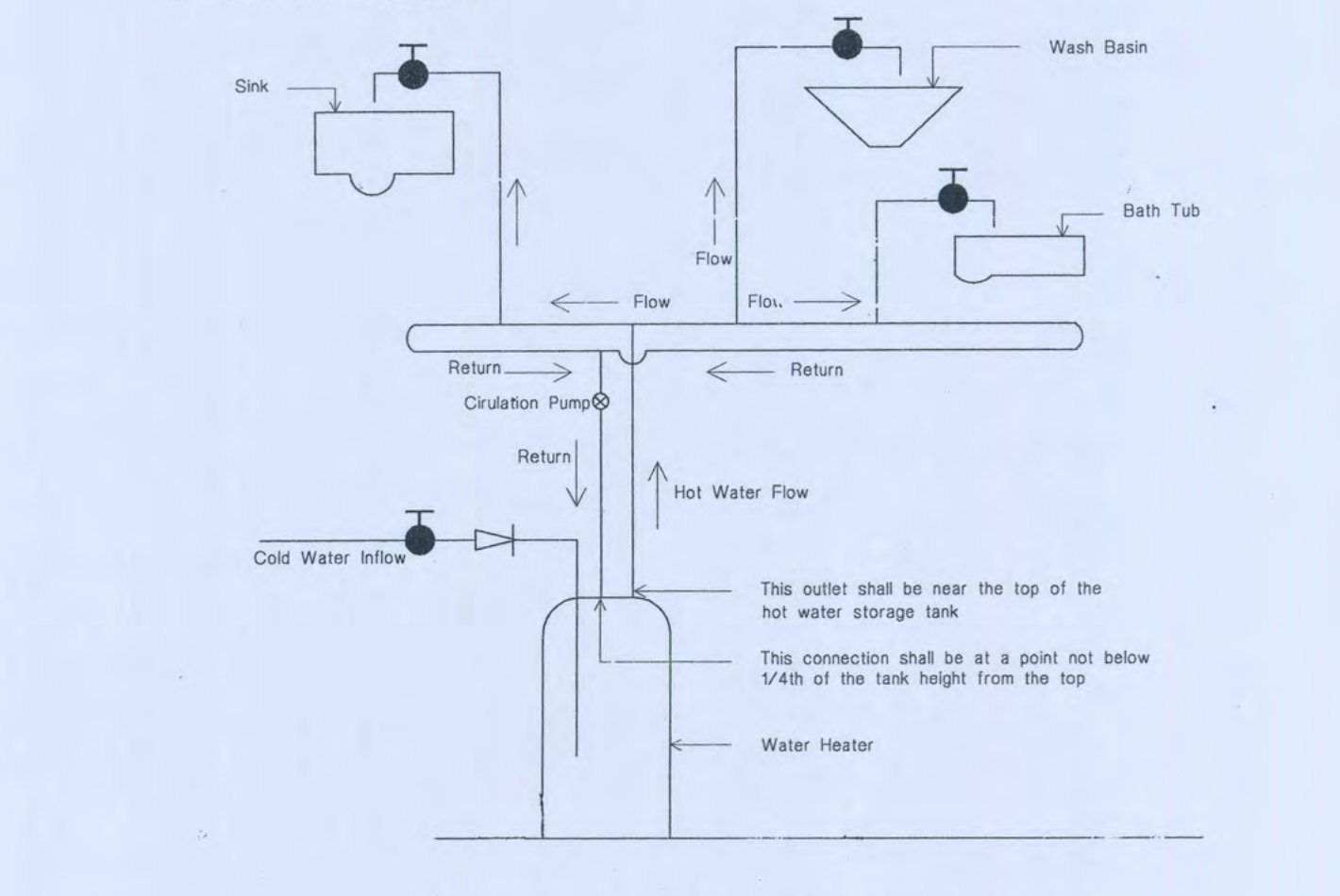
Table 8.6.7 Maximum Permissible Length of Hot Water Draw Off Pipe
6.11.7 Vent Pipe
The pressure type hot water heater shall be provided with a vent pipe of not less than 19 mm diameter. The vent pipe shall rise vertically above the water line of cold water tank by at least 150 mm plus 1 mm for every 30 mm height of waterline above the bottom of the water heater. The vent pipe shall be connected to the top of the hot water cylinder. The vent pipe may be used to supply hot water to the point in between the cold water tank and the hot water cylinder. The vent pipe shall not be provided with any valve or check valves. The termination of vent pipe shall be such as not to cause any accidental discharge to hurt or scald any passerby or person in the vicinity.6.12 MATERIALS AND FITTINGS
The materials and fittings for water supply and distribution pipe and for storage tank shall be in accordance with Sec 6.12.1 to 6.12.3. The materials shall comply with the standards listed in Part 5 and those specified in this section.6.12.1 Water Supply Service and Distribution Pipes
Water supply service and distribution pipes shall conform to the standards listed in Tables 8.6.8 and 8.6.9. The working pressure of pipes laid inside the building or underground shall have a minimum working pressure of 1.1 MPa at 23°C. In case of water supply exceeding 1.1 MPa pressure, the piping material shall have at least a rated working pressure equal to the highest available pressure. The hot water distribution piping shall have a minimum pressure of 550 kPa at 80°C. Polyvinyl chloride (PVC) plastic pipes shall not be used exposed and unprotected as riser or water distribution pipe. Polythene or unplasticized PVC shall not be installed near the heaters or hot water piping. Lead pipes may be used only for flushing and overflow purposes in a water supply system.
Table 8.6.8 Water Supply Service Pipe
Table 8.6.9 Water Distribution Pipe
6.12.2 Pipe Fittings
The pipe fittings shall be in accordance with the standards listed in Table 8.6.10 and those specified in Part 5.
Table 8.6.10 Pipe Fittings
6.12.3 Concrete, Prestressed or Ferrocement Structures
The properties of the materials used for storage tank or such other structures shall conform to the material standards specified in Part 5 of the Code.6.13 HANGERS AND SUPPORT
The piping system shall be installed with proper hangers and support to minimize undue strains and stresses. All fixtures and fittings shall be provided with hangers and support to secure them properly.6.13.1
Hangers, anchors and strapping materials shall be strong and ductile and shall not promote galvanic action.
Table 8.6.11 Hanger Spacing
6.13.2
Vertical and horizontal piping shall be supported in accordance with Table 8.6.11.6.14 WORK ON SITE
6.14.1 Excavation of Trenches
The width of excavation trench shall be at least 0.4 m more than the outside diameter of the pipe. The depth of ground cover shall be at least 0.9 m under roadway or 0.75 m under garden from the top surface of the pipe to the ground surface. The bottom of the trench shall be carefully prepared so that the pipe will be bedded well for its entire length on firm surface.6.14.2 Laying of Pipe
In sloping ground, the pipe laying shall proceed in upward direction. The pipe shall be provided with anchor blocks to withstand hydraulic pressure.6.14.3 Laying of Pipe Through Ducts, Chases, Notches or Holes
Provisions for laying pipes in ducts or chases shall be made during the time of construction. When these will be cut into existing walls, they shall be large enough with smooth finishing for fixing the pipe and to accommodate thermal expansion. Piping subject to external pressure shall not be laid in notches or holes.6.14.4 Lagged Piping
Lagged piping shall be entirely covered with waterproof and fire insulating materials before their attachment to the walls outside the building and shall be anchored with the wall keeping a gap in between the wall and the piping.6.14.5 Jointing of Pipes
All joints and connections shall be gas tight and water tight for the pressure required by the test in accordance with Sec 6.15.2. The joints between different pipings and fittings for water supply shall conform to the standards cited against them in Table 8.6.12. The requirements for the joints not specified in the table shall be subject to the approval of the Authority.
Table 8.6.12 Joints Between Different Pipings and Fittings
6.14.6 Special Care for Rat Proofing
The location and installation of water meter box shall be such as not to permit the entrance of rats into the building. The openings through walls, floors or ceilings for the installation of pipings shall be closed by using proper collars to prevent the entrance of rats.6.15 INSPECTION, TESTING AND COMPLETION CERTIFICATE
6.15.1 Inspection
Pipings and joints shall not be enclosed, concealed or covered until they have been inspected and approved by the Authority. All piping and fixtures shall be inspected for satisfactory supports and protection from damage and corrosion.6.15.2 Testing
After installation of the entire water supply system or part thereof, it shall be tested and approved by the Authority before its use. a) Testing of Water Mains : The section of the main to be tested shall be charged with water carefully by providing a 25 mm inlet with a stop cock to expel all air from the main. The main shall be allowed to stand full of water for a few days. After that the mains shall be tested to a pressure of 500 kPa or double the maximum working pressure, whichever is greater for at least 5 minutes. The system shall be able to maintain the above test pressure. b) Testing of Distribution Pipes and Fixtures : The distribution system to be tested shall be slowly and carefully charged with water to expel all air from the system and to avoid all shocks and water hammer. The piping and fittings shall be absolutely water tight when all draw off taps are closed. The system shall be able to maintain the pressure and flow required under working conditions. c) Testing of Hot Water System : The entire hot water system shall be tested for the maximum rated temperature and pressure of hot water storage system. The system shall be able to maintain the required test pressure. All safety devices shall be tested for their proper operation.6.15.3 Completion Certificate
The licensed plumber shall issue completion certificate in a prescribed form (Appendix Q) on completion of the water supply system or part thereof for inspection and testing. After testing, the Authority will allow the water connection from the water main (if any) and give the final approval (Appendix Q) to use the system.6.16 CLEANING AND DISINFECTING THE SYSTEM
6.16.1 General
The new and repaired potable water supply system including storage tank shall be disinfected before their use. The existing water supply system shall be cleaned and disinfected depending upon the quality of water. The storage tank shall be cleaned and disinfected at least once a year.6.16.2 Disinfection Procedure
The following procedure may be adopted to disinfect the plumbing system : a) The water supply system or storage tank shall be flushed with potable water until clean water appears at the outlets. b) The system or part thereof which requires disinfection shall be filled up with chlorinated water containing 50 mg/l of chlorine for 24 hours or for 3 hours with a chlorinated water of chlorine concentration of 200 mg/l. c) After the period of disinfection, the system shall be flushed with potable water until the chlorine is completely removed from the water in the system. d) The above procedure shall be repeated until the bacteriological examination shows presence of no water contamination within the system.6.17 GUIDE TO MAINTENANCE
The owner or his/her designated agent shall maintain the water supply system in a safe operating condition as specified by the Code.6.17.1
The storage tank shall be inspected regularly and shall be cleaned and disinfected periodically. Metal tanks showing the sign of corrosion shall be coated as specified in Sec 6.7.2.2.6.17.2
The overflow pipes of storage tank shall be inspected regularly to keep the flow free from obstruction.6.17.3
A periodical examination of water quality may be made.6.18 HEALTH CARE WATER SUPPLY
6.18.1 General Requirement
All hospitals shall have at least two service pipes from the individual water supply source or from the water main for supply water without any interruption. For roof storage system, the hospital shall have at least two storage tanks such that each of them is capable of serving the water distribution system in absence of the other. All special fixtures shall be installed without interference to the transportation and to the safety of patient and staff.6.18.2 Hot Water Supply
All hospitals shall be equipped to supply hot water as required by different fixtures and equipment.6.18.3 Water Supply Protection
The water supply connection to all special equipment or fixtures shall be protected against backflow, flooding, fouling and contamination of water supply system in accordance with Sec 6.9.6.19 INDIVIDUAL WATER SUPPLY SYSTEM
6.19.1 General
In the absence of a public water supply, the individual potable water source shall be used to supply water in a distribution system. The following water sources may be used for individual water supply purposes : drilled well, dug well, driven well, spring, infiltration gallery.6.19.2 Water Requirements
The capacity of source shall be sufficient to supply water as specified in Sec 6.5.6.19.3 Quality of Water
Water from developed well or cistern shall meet the potable water quality standard requirements specified by the Department of Environment, Bangladesh.6.19.4 Chlorination
The well or cistern shall be chlorinated after their construction or repair.6.19.5 Location of Water Source
The minimum distance of water source and pump suction line from potential sources of contamination shall be in accordance with Table 8.6.13.
Table 8.6.13 Distance from Potential Sources of Contamination