5.1 GENERAL
5.1.1 Purpose
The purpose of this chapter is to provide minimum standards for regulating and controlling the design, construction, installation, quality of materials, location, operation, maintenance and use of lifts, escalators and moving walks to ensure public safety and welfare.5.1.2 Scope
5.1.2.1
The provisions of this chapter shall apply to the erection, installation, alteration, repair, relocation, replacement, addition to, operation and maintenance of lifts, escalators and moving walks.5.1.2.2
Additions, alterations, repairs and replacement of equipment or systems shall comply with the provisions for new equipment and systems.5.1.2.3
Where, in any specific case, different sections of the code specify different materials or other requirements, the most restrictive one shall govern. Where there is a conflict between a general requirement and a specific requirement, the specific requirement shall be applicable.5.1.2.4
It shall be unlawful to install, extend, alter, repair or maintain lift, escalator or moving walk systems in or adjacent to buildings except in compliance with this Code.5.1.3 Terminology
This section provides an alphabetical list of the terms used in and applicable in this chapter of the Code. In case of any conflict or contradiction between a definition given in this section and that in Part 1, the meaning provided in this section shall govern for interpretation of the provisions of this chapter. BALUSTER : One of the upright supports of a hand rail. BALUSTRADE : A row of balusters meant for supporting moving hand rails. BASEMENT STOREY : The lower storey of a building below or partly below the ground level. BUFFER : A device designed to absorb the impact of the falling car or counter weight. CALL INDICATOR : A visual and audible device in the car to indicate to the attendant the lift landings from which the calls have been made. CAR BODY WORK : The enclosing body work of the lift car which comprises the sides and roof, and is built upon the car platform. CAR FRAME : The supporting frame to which the platform of the lift car, its safety gear, guide shoes and suspension ropes are attached. CAR PLATFORM : The part of the lift car which forms the floor and directly supports the load. CAR SPEED : See RATED SPEED (LIFT). COMPLATE : A pronged plate that forms part of an escalator (or moving walk) landing and engages with the Cleats of the steps (or treadway) at the limits of travel. CONTROL SYSTEM : The system of equipment by means of which starting, stopping, direction of motion, speed, acceleration, and retardation of the moving member are controlled. COUNTER WEIGHT : A weight or combination of weights to counterbalance the weight of the car and part of the rated load. DETERMINING ENTRANCE LEVEL : The inside floor level at the entrance to the building. DOOR, CENTRE OPENING SLIDING : A door which slides horizontally and consists of two panels which open from the centre and are so interconnected that they move simultaneously. DOOR, HINGED : The hinged portion of the lift well enclosure which closes the opening giving access to the landing. DOOR, MIDBAB COLLAPSIBLE : A collapsible door with vertical bars mounted between the normal vertical members. DOOR, SINGLE SLIDE : A single panel door which slides horizontally. DOOR, TWO SPEED : A two panel door which slides horizontally in the same direction wherein each panel has different operating speed and reaches the ends simultaneously. DOOR, VERTICAL, BIPARTING : A door or shutter which slides vertically and consists of two panels or sets of panels that move away from each other to open and are so interconnected that they move simultaneously. DRIVING MACHINERY : The motorized power unit for driving the lift, escalator or moving walk. DUMBWAITER : A small lift with a car which moves in guides in a substantially vertical direction, has net floor area, total inside height and capacity not exceeding 0.9 m², 1.25 m and 225 kg respectively and is exclusively used for carrying materials and no person. It may or may not be provided with fixed or removable shelves. ENCLOSED WELL : The lift well having enclosure walls of continuous construction without openings except for doors at landings. ESCALATOR : A power driven, inclined, continuously moving stairway used for carrying passengers from one level to another. FLOOR : The lower surface in a storey on which one normally walks in a building. The general term ‘floor’, unless otherwise specifically mentioned shall not refer to a ‘mezzanine floor’. GOVERNOR : A device which automatically actuates safety devices in the event of over speed of the equipment. GUIDES (LIFT) : The members used to guide the movement of a lift car or counterweight in a vertical direction. HANDLING CAPACITY : The capacity of the lift system to carry passengers during a five minute peak period, expressed as the percentage of the estimated total population handled. HOSPITAL LIFT : A lift normally installed in a hospital, nursing home or clinic and designed to accommodate one number bed/stretcher along its depth, with sufficient space all around to carry a minimum of three attendants in addition to the lift operator. INTERVAL : Average time gap(s) between consecutive lifts leaving the ground floor or passing any specific floor. LANDING : That portion of a building or structure used for the reception and discharge of passengers or goods or both into and from a lift car, escalator or moving walk. LANDING CALL PUSH BUTTON (LIFT) : A push button fitted at a lift landing, either for calling the lift car or for actuating the call indicator. LANDING DOOR (LIFT) : The hinged or sliding portion of a lift well enclosure, controlling access to a lift car at a landing. LANDING PLATE : The portion of the landing immediately above the mechanism at either end of escalator or moving walk and constructed so as to give access to this mechanism in these areas. LIFT : A machine designed to transport persons or materials between two or more levels in a vertical or substantially vertical direction by means of a guided car or platform. LIFT CAR : The load carrying unit with its floor or platform, car frame and enclosing bodywork. LIFT MACHINE : The part of the lift equipment comprising motor(s) and control gear therewith, reduction gear (if any), brake(s) and winding drum or sheave, by which the lift car is raised or lowered. LIFT PIT : The space in the lift well below the level of the lowest lift landing served. LIFT SYSTEM : One or more lift cars serving the same building. LIFT WELL : The unobstructed space within an enclosure provided for the vertical movement of the lift car(s) and any counter weight(s), including the lift pit and the space for top clearance. LIFT WELL ENCLOSURE : Any structure which separates the lift well from its surroundings. LIFTING BEAM : A beam, mounted immediately below the machine room ceiling to which lifting tackle can be fixed for raising parts of the lift machine. MACHINE ROOM : The compartment allocated to house the lift machine and associated items. MACHINERY SPACE : The space occupied by the driving machine and control gear of the lift, escalator or moving walk. MEZZANINE : An intermediate floor between two floors above ground level. MOVING WALK : A power driven, horizontal or inclined, continuously moving conveyor used for carrying passengers, horizontally or at an inclination up to a maximum of 15 degree. NEWEL : An upright support of the handrail at the landing of escalator/moving walk where the handrail reverses its direction. OPEN TYPE WELL : A lift well having enclosure walls of wire grille or similar construction. OPERATION : The method of actuating the control and/or functioning any machine/equipment. OVERHEAD BEAMS (LIFT) : The members, usually of steel or reinforced concrete, which immediately support lift equipment at the top of the lift well. OVERHEAD PULLEY : An idler pulley used to change the direction of rope. PASSENGER LIFT : A lift designed for the transport of passengers. POWER OPERATED DOOR : A door operated automatically by a device initiated by a momentary pressure on the push button or by operation of the control system. RATED LOAD : The maximum load which the lift car, escalator or moving walk is designed and installed to carry safely at its rated speed.5.1.4 General Particulars
5.1.4.1
All relevant aspects of lift, escalator or moving walk installations shall be properly evaluated during the planning stage of the building in order to design the most effective conveying system.5.1.4.2
Appropriate steps shall be taken during the planning stage of the building to determine particulars of lift, escalator or moving walk and the necessary provisions to be kept in the building structure so as to meet the requirements of this Code. Appendix I. provides a brief list of particulars and provisions which are to be determined during the planning stage.5.1.4.3
The building plan submitted with the application for seeking permission of installation of lift, escalator or moving walk from the Authority shall include layout of lift, escalator or moving walk properly identified in the drawing along with the detailed particulars as per Appendix M.5.1.4.4
Specifications for lifts, escalators and moving walks shall include detailed particulars as per Appendix N.5.1.4.5
For the purpose of effective installation of lifts, escalators or moving walks, working drawings showing the layout of lifts, escalators or moving walks properly identified in the drawing, details of builders works, for example, holes and/or punches in floors or walls and supports for lifts, escalators or moving walks shall be prepared prior to the finalization of building design drawings.5.1.4.6
Necessary particulars of electrical requirements of lifts, escalators or moving walks shall be determined early in the planning stage to include it in the electrical provisions of the building.5.2 ESSENTIAL REQUIREMENTS FOR LIFTS
5.2.1 General
5.2.1.1
Lifts shall be provided in buildings more than six storeys or 20 m in height.5.2.1.2 Stretcher Facility in Lifts
a) When passenger lifts are installed in any building having more than ten storeys or a height of more than 32 m, each lift served by these lifts must have access to at least one lift with a stretcher facility in accordance with Sec 5.2.1.2(b). b) A lift required to have a stretcher facility by Sec 5.2.1.2(a) shall accommodate a raised stretcher with a patient lying on it horizontally by providing a minimum inside platform area 1275 mm wide x 2000 mm long with a minimum clear opening width of 1050 mm, unless otherwise designed to provide an equivalent facility, to allow the entrance and exit of an ambulance stretcher (minimum size 600 mm wide x 2000 mm long) in its horizontal position. These lifts shall be identified by the internationally recognized symbol for emergency medical services. c) In any multi-storied hospital and health care building there shall be at least one hospital lift having stretcher facility in accordance with Sec 5.2.1.2(b).5.2.1.3 Standby Power
a) One or more lifts shall be provided with standby power in i) A building which has more than ten storeys or a height of more than 32 m, ii) Hospital and health care buildings. b) Standby power shall be provided by an approved self contained generator set to operate automatically whenever there is a disruption of electrical power supply to the building. c) The operation of the standby power system shall be as follows : i) Where only one lift is installed, the lift shall transfer to standby power within 60 seconds after failure of normal power. ii) Where two or more lifts are controlled by a common operating system, all lifts may be transferred to standby power within 60 seconds after failure of normal power, or if the standby power source is of insufficient capacity to operate all lifts at the same time, all lifts shall be transferred to standby power in sequence, shall return to the designated landing and discharge their load. After all lifts have been returned to the designated landing, at least one lift shall remain operable from the standby power.5.2.1.4 Responsibility of the Owner
a) It is the responsibility of the owner of the premises where the lift will be installed, to obtain necessary permission from the Authority before the erection of lifts(s) and for the subsequent commissioning and operation of lift (s). b) The owner shall conduct periodic inspection and maintain the installation in safe working condition at all times. c) Conformity with the provisions of this Code does not relieve the owner of his responsibility to satisfy the requirements of any other Act, Regulations or Ordinances that may be in force from time to time.5.2.1.5 Conformity by Bangladesh Electricity Act
All electrical work in connection with electrical lifts shall be carried out in accordance with the provisions of the latest Bangladesh Electricity Act and the provisions of any of its bye-laws and regulations, and shall also comply with the requirements of Chapter 2 of Part 9 of this Code.5.2.1.6
For detailed specifications of lifts, escalators and moving walks reference shall be made to the latest edition of the ANSI/ASME A 17.1 code or the European EN81 code.5.2.2 Safety Considerations
5.2.2.1 Fire Protection
a) Necessary provisions shall be kept to prevent spread of fire through the lift well. Adequate measures shall also be taken to reduce the possibility of spread of fire from the machine room into the lift well. b) Lift well enclosures and machine room shall be constructed with fire resistant materials. In case of fire, the lift well enclosure shall not give off harmful gas or fumes. c) Where lift enclosures are fire rated, manually closing doors at the enclosure well shall have a fire rating equal to that of the enclosure well and automatically closing doors shall have a fire rating equal to one-half of that of the enclosure well.5.2.2.2 Fire Switch
When required fire switch shall be provided, the function of which is to enable the fire authority to take over complete control of one or more lifts in an installation by operating with a fireman’s key.5.2.2.3
Warning signs against use of the lifts during a fire shall be displayed near every call button for a passenger lift in accordance with Sec. 5.2.10.3 (c).5.2.2.4
Efficient automatic devices shall be provided and maintained in each lift to stop the car by suitable braking devices and to cutoff power from the motor whenever excessive descending speed is attained.5.2.2.5
Efficient automatic devices shall be provided and maintained in each lift to cut off power from the motor if the car over travels either the top or bottom terminal landing.5.2.2.6
There shall have standard cranking system operable from the lift machine room to move the car manually, during a power failure, to the nearest higher or lower landing for evacuation of passengers.5.2.2.7
There shall have arrangement for emergency unlocking of the landing and lift door with a special key from any landing for evacuation as well as for maintenance .5.2.2.8
Necessary protection shall be taken against breaking of steel rope.5.2.3 Lift Cars
5.2.3.1
Lift cars shall have net inside area for different loading capacities not more than that shown in Table 8. 5.1.5.2.3.2
Lift car frame shall be of steel construction having sufficient strength to support safely the rated load, the lift car and all requisite accessories.5.2.3.3
There shall be provisions for elastic isolators between metal parts to ensure low vibration and low noise during car travel. Table 8.5.1 Maximum Inside Net Platform Areas for Various Rated Loads5.2.3.4
The car bodywork shall be of sufficient mechanical strength to resist accidental impact by users or goods. The roof, solid or perforated, shall be capable of supporting two persons or a minimum load of 150 kg. Perforations shall be sufficiently close in mesh not exceeding 40 mm to provide reasonable protection against falling articles and any person travelling in the car.5.2.3.5
The floor shall be a smooth nonslip surface. If carpeting is used, it shall be securely attached, heavy duty, with a tight weave and low profile, installed without padding.5.2.3.6
A handrail shall be provided on at least one wall of the car, preferably the rear. The rails shall be smooth and the inside surface at least 38 mm clear of the walls at a nominal height of 800 mm from the floor.5.2.3.7
Height of the entrance to the lift car shall not be less than 2 m.5.2.3.8
The lift car door shall be power operated horizontally sliding type (noncollapsible), opened and closed by automatic means. However, if space is limited, collapsible doors may be installed in case of buildings not exceeding 8 storeys or 26 m in height, but they shall not be power operated. Where doors shall not be provided to prevent all sliding doors from jumping off the tracks and statued stops shall be provided to prevent the hanger carriage from leaving the end of the track.5.2.3.9
Car and landing doors shall open and close in full synchronization being mechanically connected to each other.5.2.3.10
Doors closed by automatic means shall be provided with door reopening device(s) which will function to stop and reopen a car door and adjacent landing door in case the car is obstructed while closing. The reopening device shall also be capable of sensing an object or person in the path of a closing door without requiring contact for activation. Door reopening devices shall remain effective for a period of not less than 20 seconds. The operating mechanism for the car door shall not exert a force than 125 N.5.2.3.11
Lift car door, when closed, shall cover the opening fully except in case of vertical disparting car doors of goods lifts. Car shall be equipped with efficient interlocking or other devices so the door cannot be opened except when the lift car is at the landing, and that the lift car cannot be moved away from the landing until the leading edge of the single slide or double speed door is within 50 mm of the nearest face of the door jamb or the leading edges of the centre opening doors are within 50 mm of contact of each other.5.2.3.12
Where the lift car has solid enclosure and doors, provision shall be made for a fan for adequate ventilation. To permit switching off of the fan and light, a separate switch shall be provided for fan and light.5.2.3.13
Any vision panel in a car door shall be fire resisting and shall be of safety wired glass or similar material. The area between vision bars or other supports shall not exceed 0.1 m². The bottom rail of a framed and glazed door shall be not less than 300 mm deep. Any projections on or recesses (including vision panels) in sliding car doors shall be kept to a minimum in order to avoid finger trapping between sliding parts of the door and any fixed part of the structure.5.2.3.14
The lift car shall be provided with a self levelling feature that will automatically bring the car to the floor landing within a tolerance of ± 13 mm under normal loading and unloading conditions. This self levelling shall, within its zone, be entirely automatic and independent of the operating device and shall correct the overtravel or undertravel. The car shall also be maintained approximately level with the landing, irrespective of load. Where no self-levelling device is provided, the levelling difference between the car and the landing shall be within ± 40 mm.5.2.3.15
Car operating panels shall be conveniently located on the side near the door so that passengers can register calls as quickly as possible. The centreline of the alarm button and emergency stop switch shall be at a nominal height of 800 mm, and the highest floor button no higher than 1.37 m from the floor. Floor registration buttons, exclusive of border, shall be a minimum of 18 mm in size, raised, flush or recessed. Visual indication shall be provided to show each call registered and extinguished when the call is answered. Depth of flush or recessed buttons when operated shall not exceed 10 mm. Markings shall be adjacent to the controls on a contrasting colour background to the left of the controls; letters or numbers shall be a minimum of 15 mm high and raised or recessed 0.75 mm. Sign plates permanently attached shall be acceptable. Emergency controls shall be grouped together at the bottom of the panel.5.2.3.16
A suitable battery operated alarm system shall be installed inside the lift car so as to raise an alarm at a convenient place for getting assistance for passengers trapped inside the lift car.5.2.3.17
A car position indicator shall be provided above the car operating panel or over the opening of each car to show the position of the car in the lift well by illuminated visual indicator corresponding to the landing at which the car is stopped or through which it is passing. In addition, an audible signal shall preferably be installed which shall sound to tell a passenger that the car is stopping at a floor served by the lift. A special button located with emergency controls may be provided, operation of which shall activate an audible signal only for the desired trip.5.2.3.18
Each lift car shall be fitted with a light and the car shall be kept illuminated during the whole period the lift is available for use.5.2.3.19
In installations with more than two lifts in a bank, a telephone or other device for two-way communication between each lift car and a convenient point outside the lift well shall preferably be provided. Markings or the international symbol for telephones shall be placed adjacent to the control on a contrasting colour background.5.2.4 Lift Well and Lift Well Enclosures
5.2.4.1
The Lift well shall only be used for housing equipment forming part of the lift installation or for its operation and maintenance. No other equipment or services shall be accommodated therein. For this purpose, the main electric supply line for lift machine shall be deemed to be part of the lift and the electric cable, if laid along the lift well shaft, shall be properly clamped to the wall.5.2.4.2
The lift well shall not form part of the ventilation system of the building.5.2.4.3
In multi-story residential buildings, hotels and hospitals, lift well shall be isolated from sleeping rooms (bed rooms) by lobbies or other spaces.5.2.4.4
Lift well shall not be located above any room, passage or thoroughfare. However, when absolutely necessary, this can only be permissible with the prior approval of the competent authority and in such case the following provisions shall be made : a) The pit shall be sufficiently strong to withstand the impact of the lift car with the rated load or the impact of the counterweight when either of these is descending at the rated speed or at governor tripping speed; b) Spring or oil buffers shall be provided for lift car and counterweight; and c) The car and counterweight shall be provided with a governor operated safety gear.5.2.4.5
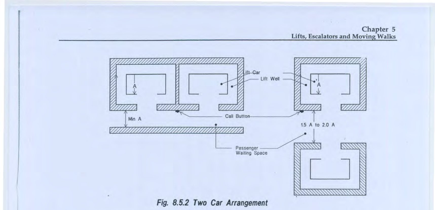
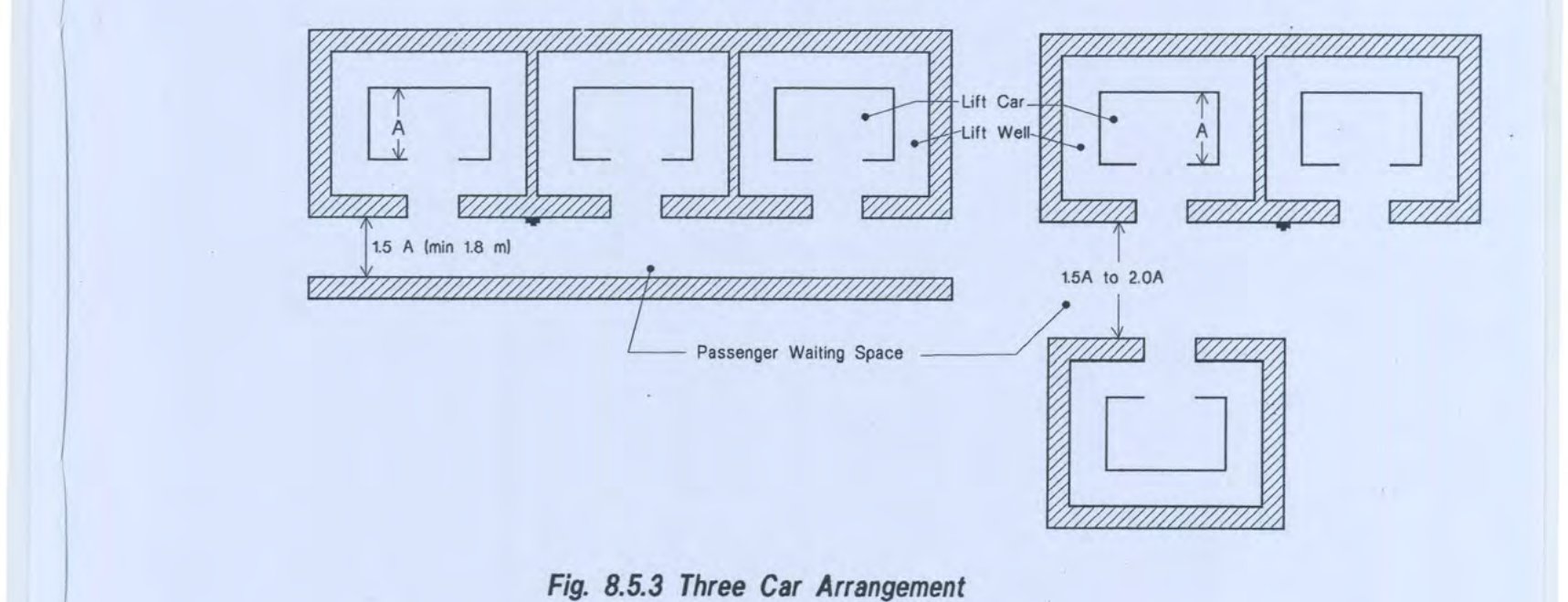
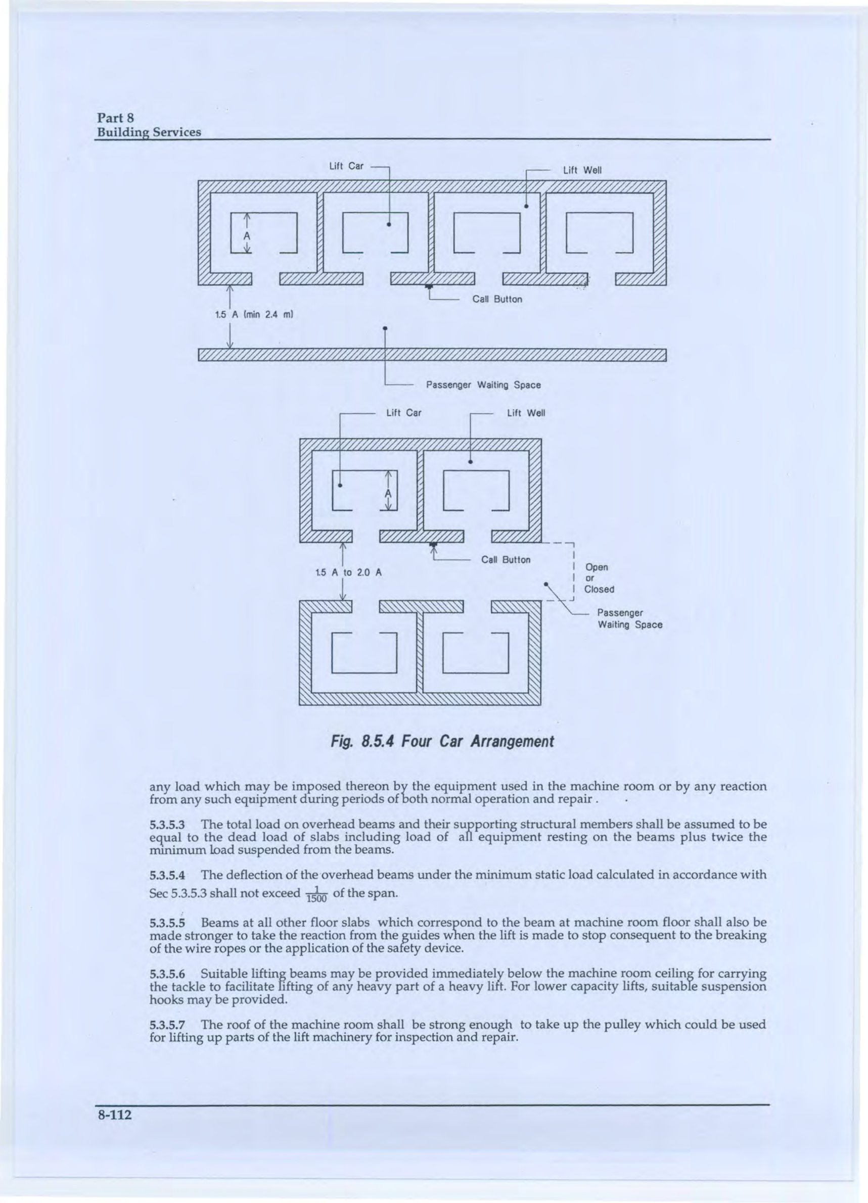
When there are three or fewer lift cars in a building, they may be located within the same lift well enclosure. When there are four lift cars, they shall be divided in such a manner that at least two separate lift well enclosures are provided. When there are more than four lifts, not more than four lift cars may be located within a single lift well enclosure.5.2.4.6
The lift car and its counterweight shall travel in juxtaposition to each other.5.2.4.7 Totally Enclosed Wells
The enclosure of the totally enclosed wells shall be continuous and shall extend on all sides from floor to floor or stair to stair. No openings except for doors at landings and necessary access panels shall be provided. The enclosure shall be of sufficient mechanical strength to support lift guides at appropriate intervals and to support in true alignment the landing doors with operating mechanisms and locking devices.5.2.4.8 Open Type Wells
a) Where lift well enclosures are constructed of wire grille or similar material, the mesh opening shall not be greater than 30 mm (except for door at landings). Such enclosures shall be of sufficient strength to resist accidental impact by users of adjoining areas or by materials or vehicles being moved in the vicinity. b) Where the clearance between the inside of an open type lift well enclosure and any moving or movable part of the lift equipment or apparatus is less than 50 mm, the openings in the enclosure material shall not be more than 10 mm. Larger openings up to 30 mm shall be permissible provided it is further protected by square mesh netting with aperture of not greater than 10 mm and wire not smaller than 1 mm in diameter.5.2.4.9
There shall be no opening in the lift well enclosure for access to the lift well through the space under the counterweight.5.2.4.10
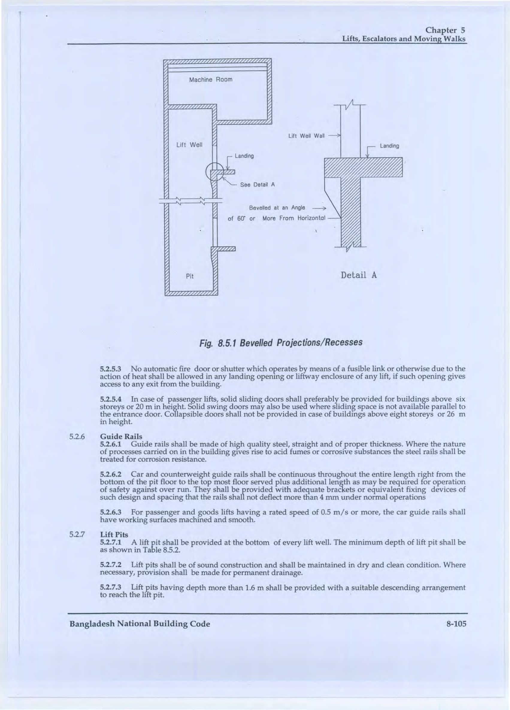
The inside surfaces of the lift well enclosures facing any car entrance shall form a smooth continuous flush surface devoid of projections or recesses. Where projections or recesses cannot be avoided, the underside of these projections / recesses shall be bevelled to an angle of 60 degrees from the horizontal by means of metal plates or other fire resistive materials as shown in Fig 8.5.1.5.2.4.11
Sufficient clearance space shall be provided between the guides for the car and the side walls of the lift well enclosure to allow safe and easy access to the parts of the safety gears for their maintenance and repairs.5.2.4.12
Maximum clearance between the inner surface of well enclosure on the landing door side and any part of car facing the surface shall be 150 mm except that 230 mm and 200 mm clearances will be permissible when power operated vertically biparting landing doors or two speed horizontally sliding doors are installed respectively.5.2.4.13
Each lift well serving more than two floors shall have vent(s) properly located at the top of the exterior wall. The vents shall be loupered with bird screens. If the well is located in such a way that no exterior vent is available for louvers, vents with connecting noncombustible ducts to an outside wall shall be provided. The area of vent shall not be less than 3.5% of the area of the lift well, provided that a minimum of 0.3 m² per lift is provided. On total required vent area not less than one-third shall be permanently open or automatically opened by a damper.5.2.5 Landing Doors
5.2.5.1
Every landing, where there is access from the landing to the lift car, shall be fitted with a landing door which shall have an efficient interlocking or other devices so ensure that the door cannot be opened except when the lift car is at the landing and that the lift car cannot be moved away from the landing until the door is closed and locked. Where mid bar collapsible doors are used for landing entrance, they shall not be power operated.5.2.5.2
Where landing doors are manually operated and no indicators are provided, vision panels of similar construction as in Sec 5.2.3.13 shall be provided.5.2.6 Guide Rails
5.2.6.1
Guide rails shall be made of high quality steel, straight and of proper thickness. Where the nature of processes carried on in the building gives rise to acid fumes or corrosive substances the steel rails shall be treated for corrosion resistance.5.2.6.2
Car and counterweight guide rails shall be continuous throughout the entire length right from the bottom of the pit floor to the top most floor served plus additional length as may be required for operation of safety against over run. They shall be provided with adequate brackets or equivalent fixing devices of such design and spacing that the rails shall not deflect more than 4 mm under normal operations.5.2.6.3
For passenger and goods lifts having a rated speed of 0.5 m/s or more, the car guide rails shall have working surfaces machined and smooth.5.2.7 Lift Pits
5.2.7.1
A lift pit shall be provided at the bottom of every lift well. The minimum depth of lift pit shall be as shown in Table 8.5.2.5.2.7.2
Lift pits shall be of sound construction and shall be maintained in dry and clean condition. Where necessary, provision shall be made for permanent drainage.5.2.7.3
Lift pits having depth more than 1.6 m shall be provided with a suitable descending arrangement to reach the lift pit.5.2.7.4
Light points shall be provided in all lift pits for facility of repair and maintenance works.5.2.7.5
In case of a group of two or more lift wells, arrangements shall be provided to allow inspection of a lift pit through the adjoining one. Table 8.5.2 Minimum Pit Depths for Traction Lifts - Overhead Machines5.2.8 Buffers
5.2.8.1
Buffers of spring or oil shall be used for safety. Buffers shall be fitted under the lift car and counterweight directly on the pit floor with suitable concrete or steel foundation. For car speeds up to and including 1.0 m/s, spring or oil buffers shall be used. Oil buffers may be used for service lifts for speeds up to 0.5 m/s. Buffers shall be located symmetrically with reference to the vertical centreline of the car/counterweight with a tolerance of 50 mm.5.2.8.2
The minimum stroke of oil buffers shall be such that the car or the counterweight on striking the buffers at 115 per cent of rated speed shall be brought to rest with an average retardation of not more than 10 m/s².5.2.8.3
When buffers are struck with an initial speed of less than 115 per cent of the rated speed, the peak retardation shall not exceed 25 m/s² for a duration more than 0.04 second, with any load in the car ranging from 75 kg to the rated load.5.2.9 Machine Room and Overhead Structures
5.2.9.1
The lift machine room shall only be used for housing lift machinery, controller and other associated apparatus and equipment. No other services or equipment shall be accommodated therein. If motor generators and other associated equipment are installed in an adjoining room, this room shall also be reserved for exclusive use of lift equipment.5.2.9.2
Lift machine room and other associated equipment rooms shall be fire proof, weather proof and adequately lighted. Means to prevent spread of fire or smoke from machine room into lift well shall be provided. Machine room shall have permanent ventilation opening direct to the open air having a free area not less than 0.1 m² per lift.5.2.9.3
The height of the machine room shall not be less than 2.30 m throughout under the lifting beam (trolley beam) to allow any portion of equipment to be accessible and removable for repair and replacement. An overhead trolley beam of steel construction of adequate strength shall be provided in the machine room, for movement of equipment during installation.5.2.9.4
The machine room shall be adequately sized and shall have sufficient floor area required for easy access to all parts of the machines and equipment located therein for purposes of inspection, maintenance or repair. Clearance space of 1 m shall be provided on those sides of control panels where maintenance is required to be carried out while the panel is energized, otherwise 0.5 m clearance space may be provided.5.2.9.5
The room shall be kept closed, except to those who are concerned with the operation and maintenance of the equipment. When the electrical voltage exceeds 220/230V dc, a danger notice plate shall be displayed permanently on the outside of the door and on or near the machinery.5.2.9.6
Machine room floor shall not have holes/punches in it except for necessary small openings for passage of ropes cables etc. If any machine room floor or platform does not extend to the enclosing walls the open sides shall be provided with hand rails or otherwise suitably guarded.5.2.9.7
All machines, pulleys, overspeed governors and similar units shall be securely fixed on the machine room floor.5.2.9.8
Adequate artificial light shall be provided in the machine room. A 15 amps 3 pin power outlet for hand operated tools and a 5 amps 2 pin electrical outlet for portable hand lamp set shall be provided in the machine room.5.2.9.9 Access to Machine Room
a) The machine room shall be provided with a direct, independent and convenient access. Access to a machine room above a lift well may be either from the roof or by an internal staircase. b) Machine room floor may be provided with a trap door. When access to the machine room is provided through the trap door, the size of the trap door shall not be less than 1.0 m x 1.0 m otherwise it may be 0.5 m x 0.5 m. Trap doors shall be hinged, opening into the machine room, of sound construction, balanced and tightly secured to minimize noise travel. Hand rails shall be provided around trap door opening . c) Where a machine room entrance is less than 1.5 m above or below the adjacent floor or roof surface, a substantial permanently attached ladder may be used. d) Where the machine room entrance is 1.5 m or more above or below the adjacent floor or roof surface, access shall be provided by means of standard stairs. e) Access to a machine room in a basement may be provided from a corridor. f) Access to a machine room via the lift well shall be prohibited.5.2.9.10
The space at secondary level in which the overhead pulleys, overspeed governors and similar machinery are housed shall have a clear height of at least 1.2 m. Where practicable, it shall have a substantial platform or floor and be provided with permanent and adequate artificial illumination. Safe and convenient access to secondary level shall be provided. Means of access between a secondary floor and machine room may be a ladder. Hand rails shall be provided at platform and access to floor.5.2.10 Hall Buttons, Hall Lanterns and Special Signs
5.2.10.1 Hall Buttons
a) Each landing shall have hall call buttons to register call for lift service for upward or downward movements. The centre line of the hall call buttons shall be at a nominal height of 1 m above the floor. b) Direction buttons, exclusive of borders, shall be a minimum of 18 mm in size, raised, flush or recessed. Visual indication shall be provided to show each call registered and extinguished when the call is answered. Depth of flush or recessed button when operated shall not exceed 10 mm.5.2.10.2 Hall Lantern
a) Where lifts are installed in totally enclosed wells, a visual signal shall be provided at each lift well entrance indicating to the prospective passenger the car answering the call and its direction of travel. An audible signal may also be included. b) The visual signal may be in the form of digital lift position indicator or directional indicator. The visual signal for each direction/lift position shall be a minimum of 62 mm in size and visible from the proximity of the hall call buttons. c) The centreline of the fire shall be located at a minimum of 1.8 m from the floor.5.2.10.3 Special Signs
a) Directional Marking: The floor at each lift well entrance on both sides of the lift well entrance, on both sides of the lift well entrance shall have left and right half visible from within the car and the lift lobby at a height of 1.5 m above the floor. Designations shall be on a contrasting background 50 mm high and raised 0.75 mm. b) Applied plates permanently attached shall be acceptable. In case of a completely enclosed lift well, a notice with the word ‘Lift’ shall be placed outside of each landing door. Electric light shall be provided such that this sign remains visible even if the surroundings are dark. c) A permanent warning sign shall be installed immediately above each hall push button station on each floor reading : IN FIRE EMERGENCY, DO NOT USE LIFT. USE EXIT STAIRS. This sign shall be in letters not less than 12 mm high. The warning sign may consist of incised, inlaid or embossed letters on a metal, wood, plastic or similar plate securely and permanently attached to the wall, or letters incised or inlaid directly into the surface of the material forming the wall.5.2.11 Electrical Wiring and Apparatus
5.2.11.1
Construction, installation and maintenance of all electrical supply lines and apparatus in connection with lift installation shall be done with proper protection so that there may be no danger to persons therefrom. No bare conductor shall be used in any lift car. Installation of electrical wiring shall conform to the provisions of Chapter 2.5.2.11.2
Electrical circuits for lights and ventilation fans, and supply to 3 pin and 2 pin socket outlets shall be controlled by a separate main switch or circuit breaker, and shall be independent of machinery power supply such that lighting circuits remain alive when power to machinery is interrupted.5.2.11.3
Suitable cautionary notice shall be affixed near every motor or other apparatus in which energy used is at a voltage exceeding 220 volts.5.2.11.4 Travelling Cable
a) Circuits which supply current to the motor shall not be included in any twin or multi-core travelling cable used in connection with the control and safety devices. b) A travelling cable which incorporates conductors for the control circuits shall be separate and distinct from that which incorporates lighting and signalling circuits in case of buildings ten storeys (32 m) or less in height or where high speed (1.50 m/s or more) lifts are employed, use of a single travelling cable for lighting and control circuits shall be permitted, provided that all conductors are insulated for the maximum voltage in the cables.5.2.11.5 Supply Cables and Switches
a) Each lift shall be provided with a main switch or circuit breaker of a capacity determined by the lift manufacturer and the incoming supply cable shall terminate in this switch. For a single lift, this switch shall be fixed adjacent to the machine room entrance. In a machine room common to more than one lift, each main switch shall be conveniently situated with respect to the lift it controls. Switches and fuses (which may form part of a distribution switch board) shall be provided for isolating the supply power to the machine room. b) Where a supply cable serves more than one lift, a diversity factor may be used for the determination of conductor size. The actual diversity factor to be adopted shall be decided by the lift manufacturer.5.2.11.6 Earthing
All electrical machinery/equipment viz. electric motor, winding machine, control panel etc. which normally carry mains current shall be properly connected to the earthing system. Similarly all metallic cases, covers of door interlocks, door contacts, call and control buttons, stop buttons, car switches, limit switches, function boxes and similar electrical fittings which normally carry only the control current shall also be properly connected to the earthing system. All earthing terminal and earthing conductors in this regard shall conform to the requirements of Chapter 2.5.3 DESIGN CONSIDERATIONS
5.3.1 Number of Lifts and Capacity
5.3.1.1
The number of lifts, car capacity and speed of the lift shall be selected to have the most effective lift system. The lift system shall be able to handle adequate number of passengers during peak hours and at the same time Interval and Travel Time shall be within reasonable limits.5.3.1.2
The average Interval shall not be more than shown in Table 8.5.3. The Travel Time shall not exceed 150 seconds.5.3.1.3
The passenger handling capacity (H) of a lift system for different occupancies in terms of the number of passengers to be handled in the building in a five minute peak period shall not be less than that indicated in Table 8.5.3.5.3.1.4
For the purpose of population estimation, the density of people shall be based on the actual number of occupants, but in no case less than those specified in Table 8.5.4. The occupant load of a mezzanine floor shall be taken into account for working out the population for a particular floor to which the mezzanine floor discharges its loads. Table 8.5.3 Maximum Interval and Minimum 5-minute Handling Capacity for Different Occupancy
Table 8.5.4 Occupant Load for Estimation of Population
5.3.1.5
The car speed for the different types of lifts in different occupancies shall normally be as given in Table 8.5.5. A higher or lower speed lift may be used in special cases when conditions warrant use of such lifts. Table 8.5.5 Car Speed for Lift in Different Kinds of Usage5.3.2 Shape and Size of Lifts
5.3.2.1
Careful analysis shall be performed during selection of shape and size of lifts so as to get full advantage of its shape for the most effective use of lifts and building space.5.3.2.2
The dimensions of the car platform shall be such that the car will not exceed its rated load when packed full. Net inside area of the lift car shall be as per Sec 5.2.3.1. Note: i) For the same platform area, a lift having higher width to depth ratio can accommodate more passengers and takes less time for passenger transfer. ii) The width of the car is determined by the width of the entrance and the depth of the car is regulated by the loading.5.3.3 Location and Arrangement of Lifts
5.3.3.1
A thorough investigation shall be carried out for assessing the most suitable location for lift(s) while planning the building. It shall take into account future expansions, if any.5.3.3.2
The lifts shall be easily accessible from all entrances to the building. For maximum efficiency, they shall be grouped near the centre of the building. Walking distance from the lift to the farthest office or suite shall not exceed 60 m.5.3.3.3 Arrangement of Lifts
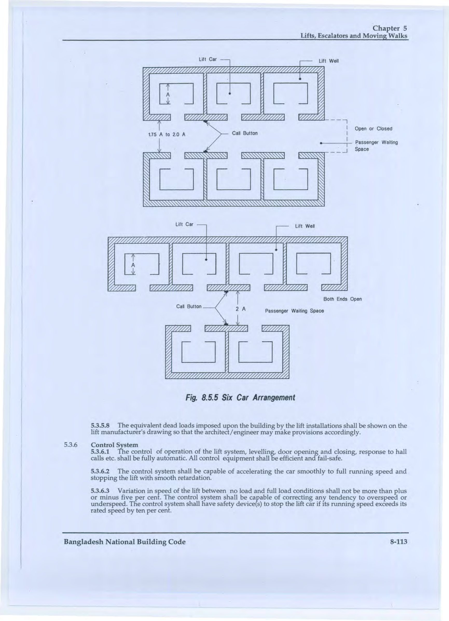
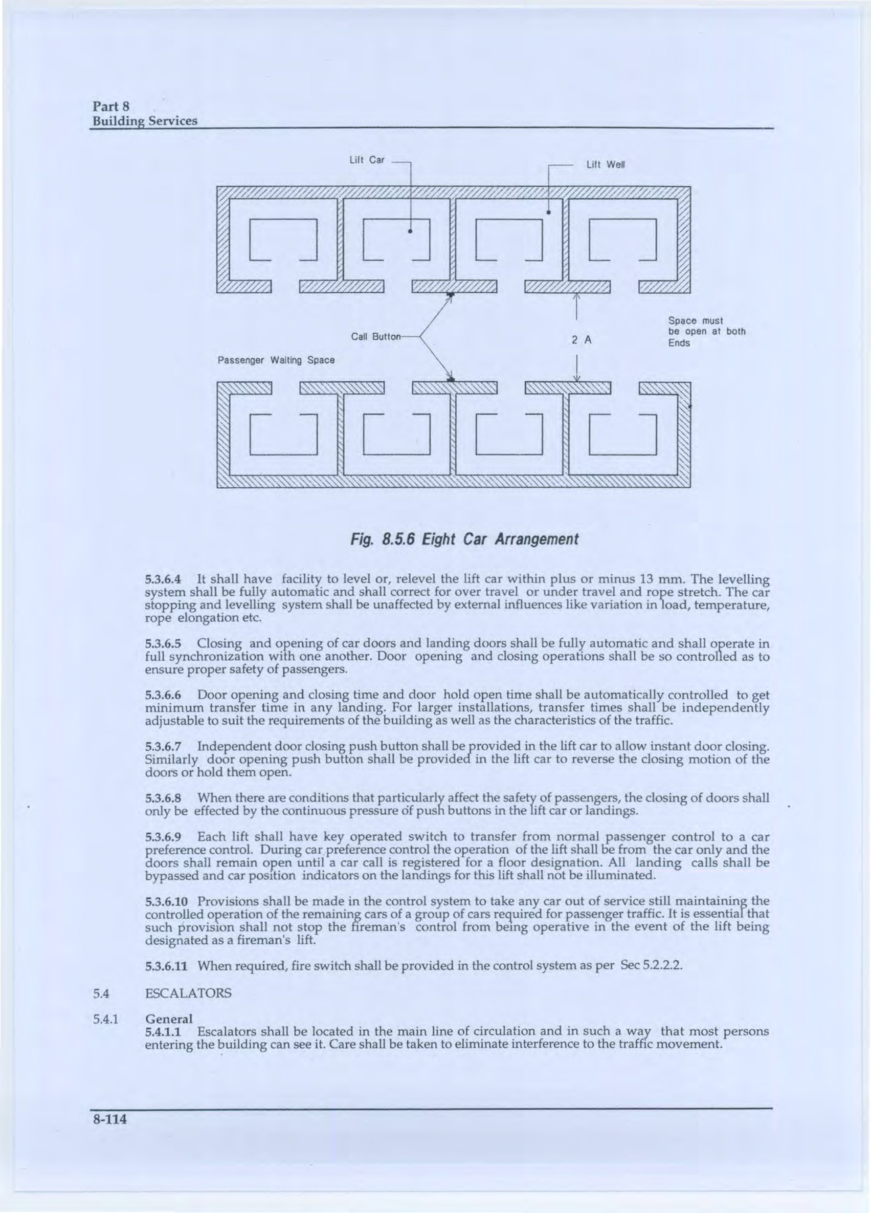
a) When more than one lift cars are installed in a group, they shall be arranged side by side or in two rows facing each other. Separation of lifts in the group shall be avoided. b) The lobby in front of lifts shall be wide enough to allow sufficient space for waiting passengers and proper vision of hall button and hall lanterns. Fig 8.5.2 to 8.5.6 give acceptable arrangements of lifts in a group with acceptable space for waiting passengers. More space shall be allowed in front of the lifts in the main floor than in the upper floors.