
6.1 ANALYSIS AND DESIGN - GENERAL CONSIDERATIONS
6.1.1 Convention and Notation
Unless otherwise explicitly stated, the following units shall be implicit for the corresponding quantities in the design and other expressions provided in this chapter:6.1.1.1 Notation
= gross area of section = specified compressive strength of concrete = specified yield strength of steel = required strength to resist factored loads or related internal moments and forces = strength reduction factor.6.1.2 General
6.1.2.1
Members shall be designed for adequate strength in accordance with the provisions of this chapter, using load factors specified in Sec 2.7.5.1 and strength reduction factors in Sec 6.1.4.6.1.2.2
Design of reinforced concrete members using Working Stress Design method (Chapter 7) is also permitted.6.1.2.3
Structures and structural members shall be designed to have design strength at all sections at least equal to the required strength (U) calculated for the factored loads and forces in such combinations as are stipulated in Chapter 2, Loads. The nominal strength provided for the section multiplied by the strength reduction factor shall be equal to or greater than the calculated required strength U.6.1.2.4
Members shall also meet all the other requirements of this Code to ensure adequate performance at service loads.6.1.2.5
Yield strength of reinforcement shall not be taken more than 550 N/mm².6.1.3 Loading
Loads and their combinations shall be in accordance with the requirements specified in Chapter 2, Loads.6.1.4 Design Strength
6.1.4.1
Design strength provided by a member, and its connections to other members, in terms of flexure, axial load, shear, and torsion, shall be taken as the nominal strength calculated in accordance with the requirements and assumptions of this chapter, multiplied by a strength reduction factor .6.1.4.2
Strength reduction factor for different kinds of strength shall be as specified in Table 6.6.1.The source numbers this table “Table 6.6.1” although it appears here in Sec 6.1.4, not Sec 6.6 — preserved as printed in the gazette.
¹ For low values of axial compression, the strength reduction factor shall be increased in accordance with the provisions of Sec 6.3.5.
6.1.4.3
Calculation of development length specified in Sec 8.2 does not require a strength reduction factor.6.1.4.4
In regions of high seismic risk, strength reduction factors shall be as given above except for the following: i) Except for determining the shear strength of joints, the factor shall be 0.6 for members whose nominal shear strength is less than the shear corresponding to the development of the nominal flexural strength. The nominal flexural strength shall be determined considering the most critical factored axial loads including earthquake effects. Shear strength reduction factor for joints shall be 0.85. ii) If the transverse reinforcement does not conform to Sec 8.3.5, the strength reduction factor for axial compression and flexure shall be 0.5 for all frame members with factored axial compressive forces exceeding .6.2 BEAMS AND ONE-WAY SLABS
6.2.1 Notation
= depth of equivalent rectangular stress block as defined in Sec 6.2.3.7 = effective tension area of concrete surrounding the flexural tension reinforcement and having the same centroid as that of the reinforcement, divided by the number of bars. When the flexural reinforcement consists of different bar sizes the number of bars or wires shall be computed as the total area of reinforcement divided by the area of the largest bar used = gross area of section = total area of longitudinal reinforcement to resist torsion = area of tension reinforcement = area of compression reinforcement = area of tension reinforcement corresponding to moment of resistance = area of additional tension steel = area of reinforcement required to balance the longitudinal compressive force in the overhanging portion of the flange of a T-beam = area of skin reinforcement per unit height in a side face = area of one leg of a closed stirrup resisting torsion within a distance = area of shear reinforcement within a distance = width of compression face of member = width of that part of cross-section containing the closed stirrups resisting torsion = web width, or diameter of circular section = distance from extreme compression fibre to neutral axis = factor relating shear and torsional stress properties = distance from extreme compression fibre to centroid of tension reinforcement = distance from extreme compression fibre to centroid of compression reinforcement = thickness of concrete cover measured from extreme tension fibre to centre of bar or wire located closest thereto = modulus of elasticity of reinforcement = specified compressive strength of concrete = calculated stress in reinforcement at service loads = modulus of rupture of concrete = specified yield strength of reinforcement = overall thickness of member = moment of inertia of cracked section transformed to concrete = effective moment of inertia for computation of deflection = moment of inertia of gross concrete section about centroidal axis, neglecting reinforcement = clear span for positive moment or shear and average of adjacent clear spans for negative moment = moment of resistance of a section without compression steel = additional moment of resistance due to added compression steel and additional tension steel = moment of resistance developed by compression in the overhanging portion of the T-flange = moment of resistance developed by the web of a T-beam = maximum moment in member at stage deflection is computed = cracking moment = modified moment = maximum moment at section due to externally applied loads = nominal flexural strength = factored moment at section = axial load normal to cross-section occurring simultaneously with ; to be taken as positive for compression, negative for tension and to include effects of tension due to creep and shrinkage = spacing of shear or torsion reinforcement in direction parallel to longitudinal reinforcement = torsional moment strength provided by concrete = torsional moment strength = torsional moment strength provided by torsion reinforcement = torsional moment at section = shear at section = shear strength provided by concrete = shear strength = nominal shear strength provided by shear reinforcement = factored load per unit length of beam or per unit area of slab = shorter overall dimension of rectangular part of cross-section = shorter centre to centre dimension of closed rectangular stirrup = longer overall dimension of rectangular part of cross-section = longer centre to centre dimension of closed rectangular stirrup = quantity limiting distribution of flexural reinforcement, see Eq (6.2.35) = coefficient equal to but not more than 1.5 = factor defined in Sec 6.2.3.7 = time-dependent factor for sustained load = ratio of tension reinforcement = ratio of compression reinforcement = reinforcement ratio producing balanced strain condition in a section, see Sec 6.2.4.1 = minimum ratio of tension reinforcement = = strength reduction factor.6.2.2 Definitions
6.2.2.1 Effective Span of Simply Supported Beams
The effective span of a simply supported beam shall be taken as the smaller of the distance between the centres of bearings, or the clear distance between supports plus the effective depth.6.2.2.2 Effective Span of Continuous Beams
If the width of the support is less than of the clear span, the effective span shall be as in Sec 6.2.2.1 above. If the supports are wider than of the clear span or 600 mm, whichever is less, the effective span shall be as follows: a) For end span with one end fixed and the other continuous or for intermediate spans, the effective span shall be the clear span between supports, and b) For end span with one end free and the other continuous, the effective span shall be equal to the clear span plus half the effective depth of the beam or the clear span plus half the width of the discontinuous support, whichever is less. In case of monolithic frames, the effective span shall be equal to the distance between intersections of the centre lines of the connecting members.6.2.2.3 Effective Length of Cantilever
The effective length of a cantilever shall be taken as its length to the face of the support plus half its effective depth except where it forms the end of a continuous beam where the length to the centre of the support shall be used.6.2.2.4 One-way Slab
Slabs in which the deflected surface is predominantly cylindrical shall be termed one-way slabs spanning in the direction of curvature. Such slabs shall included cantilever slabs, slabs supported on two opposite sides, and those supported on all four sides with the longer span greater than twice the shorter span. Curvatures, and consequently bending moments, in such slabs shall be assumed to be the same for all strips spanning in the shorter direction or in the direction of predominant curvature, the slab being designed to resist flexural stresses in that direction only.6.2.3 Design Assumptions
6.2.3.1
Strength design of members for flexure and axial loads shall be based on assumptions given in Sec 6.2.3.2 through 6.2.3.7 shall satisfy compatibility and equilibrium requirements.6.2.3.2
Strains in the steel and the concrete shall be assumed directly proportional to the distance from the neutral axis.6.2.3.3
Maximum compressive strain in the extreme compression fibre of concrete shall be assumed equal to 0.003.6.2.3.4
The stress in steel shall be the product of its strain and its modulus of elasticity, , until the steel reaches its yield strength, whereafter the stress in steel shall be taken as equal to .6.2.3.5
Tensile strength of concrete shall be neglected in calculations of axial and flexural strengths of reinforced concrete.6.2.3.6
The concrete stress block may be taken as any shape that can be justified by tests.6.2.3.7
Requirements of Sec 6.2.3.6 above may be considered satisfied by an equivalent rectangular concrete stress distribution defined by the following. a) Concrete stress of shall be assumed uniformly distributed over an equivalent compression zone bounded by edges of the cross-section and a straight line located parallel to the neutral axis at a distance from the fibre of maximum compressive strain. b) Distance from fibre of maximum compressive strain to the neutral axis shall be measured in a direction perpendicular to that axis. c) Factor shall be calculated as follows:6.2.4 General Principles and Requirements
6.2.4.1
Balanced strain conditions exist at a cross-section when tension reinforcement reaches the strain corresponding to its specified yield strength just as concrete in compression reaches its assumed ultimate strain of 0.003.6.2.4.2
For flexural members and for members subject to combined flexure and axial load, the ratio of reinforcement provided shall not exceed 0.75 of the ratio that would produce balanced strain condition for the section. For members with compression reinforcement, the portion of equalized by compression reinforcement need not be reduced by the 0.75 factor.6.2.4.3
Compression reinforcement in conjunction with additional tension reinforcement may be used to increase the strength of flexural members.6.2.4.4
Spacing of lateral supports for a beam shall not exceed 50 times the least width of compression flange or face. Effect of lateral eccentricity of load shall be taken into account in determining spacing of the lateral supports.6.2.5 Continuous Beams
Continuous beams shall be analysed in accordance with Sec 6.2.5.2 and designed and detailed to resist the moments and shear forces according to Sec 6.2.6 and 6.2.7.6.2.5.1 Arrangement of Loads
The arrangement and combination of loads shall be in accordance with the provisions of Sec 1.4.2(a), 1.4.3(a), 2.3.3.1 and 2.7.5.1.6.2.5.2 Methods of Analysis
a) All members of continuous construction shall be designed for the maximum effects of factored loads as determined by the theory of elastic analysis, except as modified according to Sec 6.2.5.3. b) In lieu of exact analysis, the approximate expressions given in Table 6.6.2 for moments and shears are permitted to be used for design of continuous beams and one-way slabs, provided that: i) there are two or more spans, ii) spans are approximately equal, with the larger of two adjacent spans not greater than the shorter by more than 20 per cent, iii) loads are uniformly distributed, iv) unit live load does not exceed 3 times the unit dead load, and v) members are prismatic. Table 6.6.2: Approximate Moments and Shears in Continuous Beams6.2.5.3 Redistribution of Negative Moments
a) Except where approximate values for moments are used, negative moments calculated by elastic theory at the supports of continuous flexural members for any assumed loading arrangement may be increased or decreased by not more than b) The modified negative moments shall be used for calculation of the moments at sections within the spans. c) Redistribution of negative moments shall be made only when the section at which moment is reduced is so designed that or is equal to or less than , where6.2.6 Design for Flexure
6.2.6.1 Design of Rectangular Beams
a) Formula for singly reinforced beams: The following equations which are based on the simplified stress block of Sec 6.2.3.7, are applicable to singly reinforced rectangular beams along with T-beams where the neutral axis lies within the flange. where By estimating an initial value of , Eq (6.2.2) can be used to determine an approximate value of . That value can be substituted in Eq (6.2.3) to get a better estimate of and hence a new can be determined for substitution in Eq (6.2.2). b) Design formulae for doubly reinforced beams: Compression steel for a given beam is required when concrete alone cannot develop the required compression force. The following formulae shall apply to doubly reinforced beams: where and provided both tension and compression steel are stressed to at failure.6.2.6.2 Design of T-Beams
a) General i) Effective width of T-beams: Width of slab effective as T-beam flange shall not exceed one-quarter of the span length of the beam, and the effective overhanging flange width on each side of the web shall not exceed eight times the slab thickness nor one-half the clear distance to the next web. ii) Effective width of L-beams: For beams with a slab on one side only, the effective overhanging flange width shall be the minimum of one-twelfth the span length of the beam, six times the slab thickness, and one-half the clear distance to the next web. iii) Isolated beams, in which the T-shape is used to provide a flange for additional compression area, shall have a flange thickness not less than one-half the width of web and an effective flange width not more than four times the width of web. b) Formulae for T-beams: A T-beam shall be treated as a rectangular beam if where is obtained from Eq (6.2.3). In using Eq (6.2.3), if is not known, it may be initially assumed as: If , thus obtained, is greater than the beam shall be considered as a T-beam, in which case the following formulae shall be applicable: By estimating an initial value of , Eq (6.2.12) can be used to obtain an approximate value of . That value of can be substituted in Eq (6.2.13) to get a better estimate of .6.2.7 Shear and Torsion
6.2.7.1
Design for shear shall be based on where is the factored shear force at section considered and is the nominal shear strength computed by where is nominal shear strength provided by concrete in accordance with Sec 6.2.7.3 and is nominal shear strength provided by shear reinforcement in accordance with Sec 6.2.7.4(f). In determining the nominal shear strength , effect of any openings in members shall be considered. In determining , effects of axial tension due to creep and shrinkage shall be considered and effects of inclined flexural compression in variable depth members may be included.6.2.7.2
Sections located less than distance from the face of support may be designed for maximum factored shear force computed at distance , if the following conditions are satisfied: i) support reaction introduces compression into the end regions of the member in the direction of applied shear, and ii) there is no concentrated load between the face of support and the location of critical section.6.2.7.3 Shear Strength Provided by Concrete,
a) shall be computed by the provision of (i) through (iii) below unless a more detailed calculation is made in accordance with Sec 6.2.7.3 (b) below. i) For members subject to shear and flexure only, ii) For members subject to axial compression, in addition to flexure and shear iii) For members subject to significant axial tension, . b) may be computed by the more detailed calculation as follows: i) For members subject to shear and flexure only Quantity shall not be taken greater than 1.0 in computing by Eq (6.2.18), where is the factored moment occurring simultaneously with at the section considered. ii) For members subject to axial compression, Eq (6.2.18) may be used to compute with substituted for and shall not then be limited to 1.0, where However, shall not be taken greater than When as computed by Eq (6.2.19) is negative, shall be computed by Eq (6.2.20). iii) For members subject to significant axial tension where is negative for tension.6.2.7.4 Shear Strength Provided by Shear Reinforcement
a) Shear reinforcement may consist of i) stirrups placed perpendicular to axis of member, ii) bent up longitudinal reinforcement with bent portion making an angle of 30 degree or more with longitudinal tension reinforcement, iii) combinations of stirrups and bent longitudinal reinforcement. b) Design yield strength of shear reinforcement shall not exceed 410 N/mm². c) Stirrups shall extend a distance from extreme compression fibre and shall be anchored at both ends in accordance with Sec 8.2. d) Spacing limits for shear reinforcement i) Spacing of reinforcement perpendicular to axis of member shall not exceed , nor 600 mm. ii) Bent longitudinal reinforcement shall have a maximum spacing of , but not greater than 600 mm, where is the acute angle between the bent bar and the horizontal. iii) When exceeds , maximum spacings given in (i) and (ii) above shall be reduced by one-half. e) Minimum shear reinforcement i) When factored shear force exceeds one-half the shear strength provided by concrete , a minimum area of shear reinforcement shall be provided in all reinforced concrete flexural members, except slabs and footings, ribbed construction, and beams with total depth not greater than 2.5 times thickness of flange, one-half the width of web and 250 mm. ii) Where shear reinforcement is required by (i) above or by analysis, and where factored torsional moment does not exceed , minimum area of shear reinforcement shall be computed by iii) Where factored torsional moment exceeds and where shear reinforcement is required by (i) above or by analysis, minimum area of closed stirrups shall be computed by where is the area of one leg of closed stirrup. f) Design of shear reinforcement i) Where factored shear force exceeds shear strength , shear reinforcement shall be provided to satisfy Eq (6.2.14) and (6.2.15), where shear strength shall be computed in accordance with (ii) through (vii) below. ii) When shear reinforcement perpendicular to the axis of member is used, iii) When bent-up bars inclined at an angle with the horizontal, are used as shear reinforcement, iv) When shear reinforcement consists of a single bar or a single group of parallel bars, all bent up at the same distance from the support, but not greater than v) When shear reinforcement consists of a series of parallel bent-up bars or groups of parallel bent-up bars at different distances from the support, shear strength shall be computed by Eq (6.2.25). vi) Only the centre three-fourths of the inclined portion of any longitudinal bent bar shall be considered effective for shear reinforcement. vii) Shear strength shall not be taken greater than .6.2.7.5 Combined Shear and Torsion
a) At sections where factored torsional moment exceeds , shall be calculated by b) Torsion effects shall be included with shear and flexure where factored torsional moment exceeds . Otherwise, torsion effect may be neglected. For the calculation of the following conditions shall apply: i) For members with rectangular or flanged sections, the sum shall be taken for the component rectangles of the section, but the overhanging flange-width used in design shall not exceed three times the flange thickness. ii) A rectangular box section shall be taken as solid section provided the wall thickness is at least . A box section with wall thickness less than but greater than shall be taken as solid section except that shall be multiplied by . When is less than , the stiffness of the wall shall be considered. Fillets shall be provided at interior corners of box sections. c) When the equilibrium of the structure would be violated if the resisting torsional moment cannot be fully developed by the section and when the analysis takes such torsional resistance into consideration, the member shall be designed to carry that torsional moment in accordance with (d) through (k) below. d) In a statically indeterminate structure where reduction of torsional moment in a member can occur due to redistribution of internal forces, maximum factored torsional moment may be reduced to i) In such a case the correspondingly adjusted moments and shears in adjoining members shall be used in design. ii) In lieu of a more exact analysis, torsional loading from a slab shall be taken as uniformly distributed along the member. e) Sections located less than a distance from the face of support may be designed for the same torsional moment as that computed at a distance . f) Torsional moment strength Design of cross-sections for torsion shall be based on where is the factored torsional moment at the section considered and is the nominal torsional moment strength computed by where is the nominal torsional moment strength provided by concrete in accordance with (g) below and is the nominal torsional moment strength provided by torsion reinforcement in accordance with (j) below. g) Torsional moment strength provided by concrete i) shall be computed by ii) For members subject to significant axial tension, torsion reinforcement shall be designed to carry the total torsional moment, unless a more detailed calculation is made in which given by Eq (6.2.30) and given by Eq (6.2.27) are multiplied by , where is negative for tension. h) Torsion reinforcement requirements i) Torsion reinforcement, where required, shall be provided in addition to reinforcement required to resist shear, flexure and axial forces. ii) Reinforcement required for torsion shall be combined with that required for other forces, provided the area furnished is the sum of individually required areas and the most restrictive requirements for spacing and placement are met. iii) Torsion reinforcement shall consist of closed stirrups, closed ties or spirals, combined with longitudinal bars. iv) Design yield strength for torsion reinforcement shall not exceed 410 N/mm². v) Stirrups used as torsion reinforcement shall extend a distance from the extreme compression fibre and shall be anchored in accordance with Sec 8.2. vi) Torsion reinforcement shall be provided at least a distance beyond the point theoretically required. j) Design of torsion reinforcement i) Where factored torsional moment exceeds torsional moment strength , torsion reinforcement shall be provided to satisfy Eq (6.2.28) and (6.2.29), where torsional moment strength shall be computed by where is the area of one leg of closed stirrup resisting torsion within a distance and , but not more than 1.5. Longitudinal steel distributed around the perimeter of the closed stirrup shall be provided in accordance with (iii) below. ii) A minimum area of closed stirrup shall be provided in accordance with Sec 6.2.7.4(e). iii) Required area of longitudinal bar distributed around the perimeter of the closed stirrup shall be computed by or whichever is greater. Value of computed by Eq (6.2.33) need not exceed that obtained by substituting for in the same expression. iv) Torsional moment strength shall not exceed . k) Spacing limit for torsion reinforcement i) Spacing of closed stirrups shall not exceed the smaller of , or 300 mm ii) Spacing of longitudinal bars, not less than 10 mm φ, distributed around the perimeter of the closed stirrup shall not exceed 300 mm. At least one longitudinal bar shall be placed in each corner of the closed stirrups.6.2.8 Reinforcement
6.2.8.1
At any section of a beam or one-way slab, except as provided in Sec 6.2.8.2 and 6.2.8.3, where positive reinforcement is required by analysis, the ratio provided shall not be less than that given by Eq (6.2.34) for normal weight aggregate concrete. For brick aggregate concrete, shall be increased by 50 per cent. In flanged beams where the web is in tension, the ratio shall be computed for this purpose using the width of the web.6.2.8.2
Alternatively, area of reinforcement provided at every section, positive or negative, shall be at least one-third greater than that required by analysis.6.2.8.3
Reinforcement in the direction of the span shall be at least equal to that required for shrinkage and temperature according to Sec 8.1.126.2.8.4
Where primary flexural reinforcement in a slab that is considered as a T-beam flange (excluding ribbed construction) is parallel to the beam, reinforcement perpendicular to the beam shall be provided in the top of the slab in accordance with the following: a) Transverse reinforcement shall be designed to carry the factored load on the overhanging slab width assumed to act as a cantilever. For isolated beams, the full width of overhanging flange shall be considered. For other T-beams only the effective overhanging slab width need be considered. However, this reinforcement need not be additive to any other reinforcements required. b) Transverse reinforcement shall be spaced not farther apart than five times the slab thickness, nor 450 mm.6.2.9 Crack Control
6.2.9.1
This section prescribes rules for distribution of flexural reinforcement to control flexural cracking in beams and in one-way slabs.6.2.9.2
Flexural tension reinforcement shall be well distributed within the maximum flexural tension zone of a member cross-section as required by Sec 6.2.9.3 below.6.2.9.3
When design yield strength for tension reinforcement exceeds 275 N/mm², cross-section of maximum positive and negative moment shall be so proportioned that the quantity z given by does not exceed 30 kN/mm for interior exposure and 25 kN/mm for exterior exposure. Calculated stress in reinforcement at service load shall be computed as the moment divided by the product of steel area and internal moment arm. In lieu of such computations, it is permitted to take as 60% of specified yield strength .6.2.9.4
Provisions of Sec 6.2.9.3 are not sufficient for structures subject to very aggressive exposure or designed to be watertight. For such structures, special investigation and precautions are required.6.2.9.5
When flanges of T-beam construction are in tension, part of the flexural tension reinforcement shall be distributed over an effective flange width as defined in Sec 6.2.6.2(a) or a width equal to of the span, whichever is smaller. If the effective flange width exceeds of the span, some longitudinal reinforcement shall be provided in the outer portion of the flange.6.2.9.6
If the depth of the web exceeds 900 mm, longitudinal skin reinforcement shall be uniformly distributed along both side faces of the member for a distance from the nearest flexural tension reinforcement. The area of skin reinforcement on each side face shall be at least mm² per metre height. The maximum spacing of the skin reinforcement shall not exceed the lesser of and 300 mm. Such reinforcement may be included in strength computation if a strain compatibility analysis is made to determine stresses in the individual bars. The total area of longitudinal skin reinforcement in both faces need not exceed one-half of the required flexural tensile reinforcement.6.2.10 Deflection
6.2.10.1
Beams and one-way slabs shall be designed to have adequate stiffness to limit deflections or any deformations that affect strength or serviceability of a structure adversely.6.2.10.2
Minimum thickness stipulated in Table 6.6.3 shall apply for beams and one-way slabs not supporting or attached to partitions or other construction likely to be damaged by large deflections, unless computation of deflection indicates that a lesser thickness can be used without adverse effects. Table 6.6.3: Minimum Thickness of RC Beams or One-way Slabs Unless Deflections are Computed
Note: Values given shall be used for reinforcement with N/mm². For other than 410 N/mm², the values shall be multiplied by .
6.2.10.3
Deflections, when computed, shall be those which occur immediately on application of the load evaluated by the usual methods or formulas for elastic deflections, considering the effects of cracking and reinforcement on member stiffness.6.2.10.4
Unless stiffness values are obtained by a more comprehensive analysis, immediate deflection shall be computed with the modulus of elasticity for concrete as specified in Sec 5.13.2 and with the effective moment of inertia as follows, but not greater than . where6.2.10.5
For continuous members, effective moment of inertia may be taken as the average of values obtained from Eq (6.2.36) for the critical positive and negative moment sections. For prismatic members, effective moment of inertia may be taken as the value obtained from Eq (6.2.36) at midspan for simple and continuous spans, and at support for cantilevers.6.2.10.6
Unless values are obtained by a more comprehensive analysis, additional long-term deflection resulting from creep and shrinkage of flexural members shall be determined by multiplying the immediate deflection caused by the sustained load considered, by the factor where is be the value at mid span for simple and continuous spans, and at support for cantilevers. Time-dependent factor for sustained load shall be equal to6.2.10.7
Deflections computed in accordance with Sec 6.2.10.3 through 6.2.10.6 shall not exceed the limits stipulated in Table 6.6.4. Table 6.6.4: Maximum Permissible Computed Deflections
* Limit not intended to safeguard against ponding. Ponding should be checked by suitable calculations of deflection, including added deflections due to ponded water and considering long-term effects of all sustained loads, camber, construction tolerances, and reliability of provisions for drainage.
+ Limit may be exceeded if adequate measures are taken to prevent damage to supported or attached elements.
++ Long-time deflection shall be determined in accordance with Sec 6.2.10.6 but may be reduced by the amount of deflection calculated to occur before attachment of non-structural elements. This amount shall be determined on the basis of accepted engineering data relating to time-deflection characteristics of members similar to those being considered.
+++ But not greater than tolerance provided for non-structural elements. Limit may be exceeded if camber is provided so that total deflection minus camber does not exceed the limit.
6.3 COLUMNS
6.3.1 Notation
= depth of equivalent rectangular stress block as defined in Sec 6.2.3.7 = area of core of spirally reinforced compression member measured to outside diameter of spiral = gross area of section = area of tension reinforcement = total area of longitudinal reinforcement, (bars or steel shapes) = area of structural steel shape, pipe, or tubing in a composite section = width of compression face of member = distance from extreme compression fibre to neutral axis = a factor relating actual moment diagram to an equivalent uniform moment diagram = distance from extreme compression fibre to centroid of tension reinforcement = distance from extreme tension fibre to centroid of compression reinforcement = distance from extreme tension fibre to centroid of tension reinforcement = modulus of elasticity of concrete = modulus of elasticity of reinforcement = flexural stiffness of compression member = specified compressive strength of concrete = specified yield strength of reinforcement = overall thickness of member = storey height, centre to centre of floors or roofs = total factored lateral force acting within the storey = moment of inertia of gross concrete section about centroidal axis, neglecting reinforcement = moment of inertia of reinforcement about centroidal axis of member cross-section = moment of inertia of structural steel shape, pipe or tubing about centroidal axis of composite member cross-section = effective length factor for compression members = height of column, centre to centre of floors or roof = unsupported length of compression member = magnified factored moment to be used for design of compression member = factored moment at section = value of smaller factored end moment on a compression member due to the loads that result in no appreciable side sway, calculated by conventional elastic frame analysis, positive if member is bent in single curvature, negative if bent in double curvature = value of larger factored end moment on compression member due to loads that result in no appreciable side sway, calculated by conventional elastic frame analysis = value of larger factored end moment on compression member due to loads that result in appreciable side sway, calculated by conventional elastic frame analysis = nominal axial load carrying capacity at balanced strain conditions = critical load = nominal axial load carrying capacity at given eccentricity = nominal axial load carrying capacity at zero eccentricity = factored axial load at given eccentricity = stability index = radius of gyration of cross-section of a compression member = factor defined in Sec 6.2.3.7(c) = ratio of maximum factored axial dead load to maximum total factored axial load, where the load is due to gravity effects only or ratio of the maximum factored sustained lateral load to the maximum total factored lateral load in that storey = elastically-computed first order lateral deflection due to neglecting sway effect at the top of the storey relative to the bottom of the storey = moment magnification factor for frames braced against side sway, to reflect effects of member curvature between ends of compression member = moment magnification factor for frames not braced against side sway, to reflect lateral drift resulting from lateral and gravity loads = ratio of tension reinforcement = reinforcement ratio producing balanced strain conditions = ratio of volume of spiral reinforcement to total volume of core (out to out of spirals) of a spirally reinforced compression member = strength reduction factor.6.3.2 Definitions
6.3.2.1 Column
A primarily compression member, which may or may not be designed to carry simultaneous flexural forces, shall be termed a column.6.3.2.2 Braced and Unbraced Column
A column shall be termed braced against side sway when the horizontal displacement does not significantly affect the moment in the structure. When the stability index for a storey is not greater than 0.04, the column shall be considered as braced against side sway.6.3.3 Design Assumptions
6.3.3.1
The assumptions specified in Sec 6.2.3.1 through 6.2.3.7 shall apply to this section.6.3.3.2 Equivalent Circular Compression Member
In lieu of using full gross area for design, a compression member with a square, octagonal, or other shaped cross-section may be considered as a circular section with a diameter equal to the least lateral dimension of the actual shape. Gross area considered, required percentage of reinforcement and design strength shall be based on that circular section.6.3.3.3 Compression Member Built Monolithically with Wall
Outer limits of the effective cross-section of a spirally reinforced or tied compression member built monolithically with a concrete wall or pier shall be taken not greater than 40 mm outside the spiral or tie reinforcement.6.3.4 General Principles and Requirements
6.3.4.1
The principles and requirements specified in Sec 6.2.4.1 through 6.2.4.3 are applicable to this section.6.3.4.2
Design axial load strength , of compression members shall not be taken greater than the following: a) For members with spiral reinforcement conforming to Sec 8.1.10.3 or composite members conforming to Sec 6.3.10 b) For members with tie reinforcement conforming to Sec 8.1.10.46.3.4.3
Members subject to compressive axial load shall be designed for the maximum moment that can accompany the axial load. The factored axial load at given eccentricity shall not exceed given by Eq (6.3.1) and (6.3.2). The maximum factored moment shall be magnified for slenderness effects in accordance with Sec 6.3.7.6.3.5 Design
The factored axial compressive load and the simultaneous factored moment shall not exceed the limits of an area bounded by the lines , and the interaction diagram characterized by the following set of five points (as depicted in Fig 6.6.1):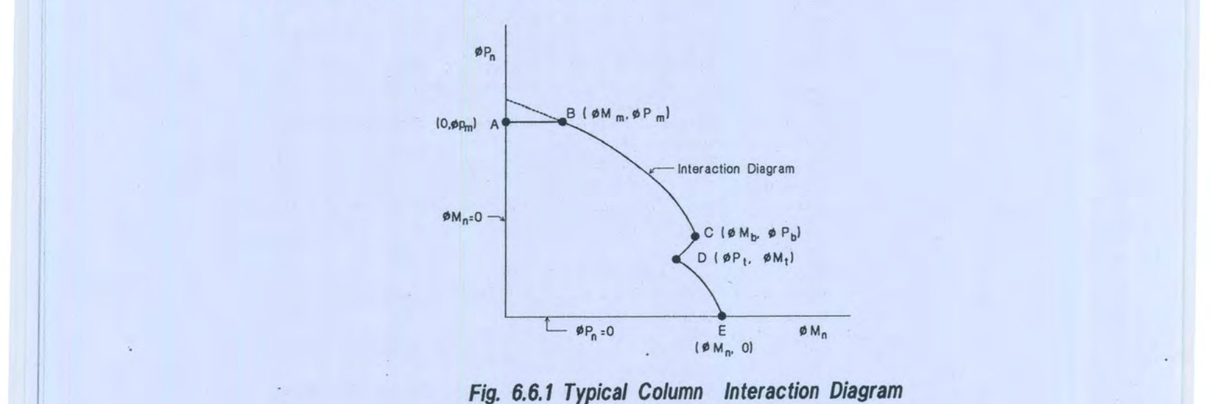
6.3.6 Reinforcement
6.3.6.1
The area of longitudinal reinforcement for non-composite compression members shall be not less than 0.01 nor more than 0.08 times gross area of section.6.3.6.2
A reduced effective area but not less than one-half the total area may be used to determine the minimum reinforcement and design strength for a compression member with a larger cross-section than that required by analysis.6.3.6.3
Minimum number of longitudinal bars in compression members shall be 3 for bars within triangular ties, 4 for bars within rectangular or circular ties, and 6 for bars enclosed by spirals conforming to Sec 6.3.6.4.6.3.6.4
Ratio of spiral reinforcement shall be not less than the value given by where is the specified yield strength of spiral reinforcement but not more than 410 N/mm².6.3.6.5
All spiral and tie reinforcement shall conform to the provisions of Sec 8.1.10.3 and 8.1.10.4.6.3.7 Slenderness Effects
6.3.7.1
Compression members shall be designed on the basis of forces and moments determined from the analysis of the structure. Such analysis shall take into account influence of axial loads and variable moment of inertia on member stiffness and fixed-end moments, effect of deflections on moments and forces, and the effects of duration of loads.6.3.7.2
In lieu of the exact procedure prescribed in Sec 6.3.7.1 slenderness effects in compression members may be evaluated in accordance with the approximate procedure presented in Sec 6.3.8.6.3.8 Approximate Evaluation of Slenderness Effects
6.3.8.1 Unsupported Length of Compression Members
a) Unsupported length of a compression member shall be taken as the clear distance between floor slabs, beams, or other members capable of providing lateral support for that compression member. b) Where column capitals or haunches are present, unsupported length shall be measured to the lower extremity of capital or haunch in the plane considered.6.3.8.2 Effective Length of Compression Members
a) For compression members braced against side sway, effective length factor shall be taken as 1.0, unless analysis shows that a lower value is justified. b) For compression members not braced against side sway, effective length factor shall be determined from Fig 6.6.2.6.3.8.3 Radius of Gyration
The radius of gyration for rectangular compression members may be taken as , where is overall cross-sectional dimension in the direction in which stability is being considered. For circular compression members, may be taken as 0.25 times the diameter. For others shapes, may be computed for the gross concrete section.6.3.8.4 Consideration of Slenderness Effects
a) The effects of slenderness may be neglected when for compression members braced against side sway, and for compression members not braced against side sway. b) For all compression members with greater than 100, an analysis as defined in Sec 6.3.7.1 shall be made.6.3.8.5 Moment Magnification
a) Compression members shall be designed using the factored axial load from a conventional frame analysis and a magnified factored moment defined by where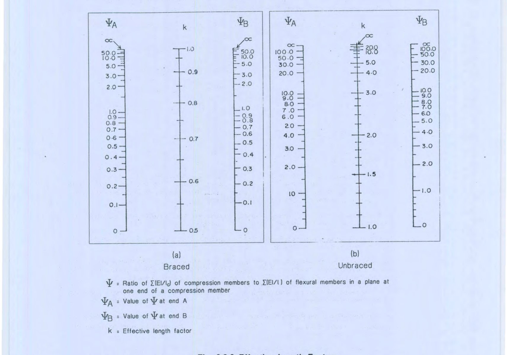
6.3.8.6 Moment Magnification for Flexural Members
Flexural members shall be designed for the total magnified end moments of the compression members at the joint, for frames not braced against side sway.6.3.8.7 Moment Magnifier for Biaxial Bending
For compression members subject to bending about both principal axes, moment about each axis shall be magnified by , computed from corresponding conditions of restraint about that axis.6.3.9 Transmission of Column Loads through Floor System
When the specified compressive strength of concrete in a column is greater than 1.4 times that specified for a floor system, transmission of column loads through the floor system shall be provided by one of the following:6.3.9.1
The concrete having strength specified for the column shall be placed in the floor system over the column area and in the slab around the column for a distance of 600 mm from the face of the column measured at the top surface of the slab. Column concrete shall be well integrated with floor concrete, and shall be placed in accordance with Sec 5.16.4.5 and 5.16.4.6.6.3.9.2
Strength of a column through a floor system shall be based on the lower value of concrete strength with vertical dowels and spirals as required.6.3.9.3
For columns laterally supported on four sides by beams of approximately equal depth or by slabs, strength of the column may be based on a composite value of concrete strength equal to 75 per cent of column concrete strength plus 35 percent of floor concrete strength.6.3.10 Composite Columns
6.3.10.1
Composite columns shall include all such members reinforced longitudinally with structural steel shapes, pipe, or tubing with or without longitudinal bars.6.3.10.2
Strength of columns shall be computed for the same limiting conditions applicable to ordinary reinforced concrete members.6.3.10.3
Any axial load assigned to concrete of a composite member shall be transferred to the concrete by members or brackets in direct bearing on the concrete of the composite member.6.3.10.4
All axial load not assigned to concrete of a composite member shall be developed by direct connection to the structural steel shape, pipe, or tube.6.3.10.5
For evaluation of slenderness effects, radius of gyration of a composite section shall be not greater than the value given by:6.3.10.6
In lieu of a more accurate calculation, the parameter in Eq (6.3.7) may be taken either from Eq (6.3.9) or by6.3.10.7 Structural Steel Encased Concrete Core
a) For a composite member with concrete core encased by structural steel, thickness of the steel encasement shall be not less than nor b) Longitudinal bars located within the encased concrete core may be considered in computing and .6.3.10.8 Spiral Reinforcement around Structural Steel Core
A composite member with spiral reinforced concrete around a structural steel core shall conform to the following: a) Compressive strength of concrete shall be at least 20 N/mm². b) Design yield strength of structural steel core shall be the specified minimum yield strength for grade of structural steel used but not to exceed 350 N/mm². c) Longitudinal bars located within the spiral shall be not less than 0.01 nor more than 0.08 times net area of concrete section, and may be considered in computing and .6.3.10.9 Tie Reinforcement around Structural Steel Core
A composite member with laterally tied concrete around a structural steel core shall conform to the following: a) Compressive strength of concrete shall be not less than 20 N/mm². b) Design yield strength of structural steel core shall be the specified minimum yield strength for grade of structural steel used but not to exceed 350 N/mm². c) Lateral ties shall extend completely around the structural steel core. d) Lateral ties shall have a diameter not less than times the greatest side dimension of composite member, except that ties shall be not smaller than 10 mm φ and not larger than 16 mm φ. e) Vertical spacing of lateral ties shall not exceed 16 longitudinal bar diameters, 48 tie bar diameters, or times the least side dimension of the composite member. f) Longitudinal bars located within the ties shall be not less than 0.01 nor more than 0.08 times net area of concrete section, and may be considered in computing for strength but not in computing for evaluation of slenderness effects. g) A longitudinal bar shall be located at every corner of a rectangular cross-section, with other longitudinal bars spaced not farther apart than one-half the least side dimension of the composite member.6.4 FLAT PLATES, FLAT SLABS AND EDGE-SUPPORTED SLABS
6.4.1 Scope
The provisions of this section shall apply to all slabs, solid, ribbed or hollow, spanning in more than one direction, with or without beams between the supports. Flat plate is a term normally attributed to slabs without beams and without drop panels, column capitals, or brackets. On the other hand, slabs without beams, but with drop panels, column capital or brackets are commonly known as flat slabs. While this section covers the requirements for all types of slabs, the provisions of Sec 6.5, Alternative Design of Two-way Edge-Supported slabs, may be used as an alternative for slabs supported on all four edges by walls, steel beams or monolithic concrete beams having a total depth not less than 3 times the slab thickness.6.4.2 Notation and Definitions
6.4.2.1 Notation
= area of shear reinforcement within a distance = perimeter of the critical section defined in Sec 6.4.7.1(b) = width of the critical section measured in the direction of the span for which moments are determined = width of the critical section measured in the direction perpendicular to = size of rectangular or equivalent rectangular column, capital or bracket measured in the direction of the span for which moments are being determined = size of rectangular or equivalent rectangular column, capital, or bracket measured transverse to the direction of the span for which moments are being determined = cross-sectional constant to define torsional properties = distance from extreme compression fibre to the centroid of longitudinal tension reinforcement, (For circular sections, need not be less than the distance from extreme compression fibre to centroid of tension reinforcement in opposite half of member) = specified compressive strength of concrete = specified yield strength of reinforcement = overall thickness of member = total depth of shearhead cross-section = moment of inertia about centroidal axis of gross section of slab times width of slab defined in notations and = flexural stiffness of beam, moment per unit rotation = flexural stiffness of column, moment per unit rotation = flexural stiffness of slab, moment per unit rotation = torsional stiffness of torsional member, moment per unit rotation = length of span in direction that moments are being determined, measured centre to centre of supports = length of span transverse to , measured centre to centre of supports = length of clear span in direction that moments are being determined, measured face to face of supports = length of shearhead arm from centroid of concentrated load or reaction = total factored static moment = required plastic moment strength of shearhead cross-section = factored moment at section = moment resistance contributed by shearhead reinforcement = nominal shear strength provided by concrete = nominal shear strength provided by shear reinforcement = factored shear force at section = factored dead load per unit area = factored live load per unit area = factored load per unit area = shorter overall dimension of rectangular part of cross-section = longer overall dimension of rectangular part of cross-section = ratio of flexural stiffness of beam section to flexural stiffness of a width of slab bounded laterally by centre lines of adjacent panels (if any) on each side of the beam = ratio of flexural stiffness of columns above and below the slab to combined flexural stiffness of the slabs and beams at a joint taken in the direction of the span for which moments are being determined = average value of for all beams on edges of a panel = minimum to satisfy Sec 6.4.5.9(a) = constant used to compute in slabs and footings = in direction of = in direction of = ratio of stiffness of shearhead arm to surrounding composite slab section = ratio of clear spans in long to short direction of two-way slabs = ratio of dead load per unit area to live load per unit area (in each case without load factors) = ratio of long side to short side of column, concentrated load or reaction area = ratio of torsional stiffness of edge beam section to flexural stiffness of width of slab equal to span length of beam, centre to centre of supports = fraction of unbalanced moment transferred by flexure at slab-column connections = fraction of unbalanced moment transferred by eccentricity of shear at slab-column connections = factor defined by Eq (6.4.7) = number of identical arms of shearhead6.4.2.2 Definitions
For the purpose of this section the following definitions shall apply. COLUMN STRIP: Column strip is a design strip with a width on each side on a column centre line equal to or , whichever is less. MIDDLE STRIP: Middle strip is a design strip bounded by two column strips. PANEL: A panel is bounded by column or wall centre lines on all sides.6.4.3 Proportioning
6.4.3.1
Thickness of slabs shall satisfy the most restrictive of the requirements of (a), (b), and (c) below. a) This provision shall apply to flat slabs and flat plates only. Minimum thickness of such slabs shall be in accordance with the provisions of Table 6.6.5 and shall not be less than the following values: i) Slabs with drop panel satisfying the requirements of Sec 6.4.3.2. — 100 mm ii) Slabs without drop panel — 125 mm Table 6.6.5: Minimum Thickness of Slab without Interior Beams
Note:
- For values of reinforcement yield stress between 250 N/mm² and 410 N/mm² minimum thickness shall be obtained by linear interpolation.
- Drop panels shall satisfy the requirements of Sec 6.4.3.2.
- For slabs with beams between columns along exterior edges, the value of for the edge beam shall not be less than 0.8.
6.4.3.2
Size of drop panel when provided shall be in accordance with the following: a) Drop panel shall extend in each direction from centre line of support a distance not less than one-sixth the span length measured from centre to centre of supports in that direction. b) Projection of drop panel below the slab shall be at least one-quarter the slab thickness. c) In computing the required slab reinforcement, thickness of drop panel below the slab shall not be assumed greater than one quarter the distance from edge of drop panel to edge of column or column capital.6.4.3.3
When column capitals are provided, that portion of the column head which lies within the largest circular cone or a pyramid that has a vertex angle of 90° and can be included entirely within the outlines of the column and the column head, shall be considered for design purposes.6.4.4 Design Procedures
6.4.4.1
Slab system may be designed by any procedure satisfying conditions of equilibrium and geometric compatibility provided that the design strength at every section is at least equal to the required strength and that all serviceability conditions, including specified limit on deflections are met.6.4.4.2
For gravity loads, the slab system may be designed by either the Direct Design Method of Sec 6.4.5 or the Equivalent Frame Method of Sec 6.4.6.6.4.4.3
For lateral loads, analysis of unbraced frame shall take into account the effects of cracking and reinforcement on the stiffness of frame members.6.4.4.4
Results of the gravity load analysis may be combined with results of the lateral load analysis.6.4.4.5
When gravity load, wind, earthquake or other lateral forces cause transfer of moment between slab and column, a fraction of the unbalanced moment shall be transferred by flexure in accordance with (b) and (c) below. a) Fraction of unbalanced moment not transferred by flexure shall be transferred by eccentricity of shear in accordance with Sec 6.4.7.5. b) A fraction of the unbalanced moment given by shall be considered to be transferred by flexure within an effective slab width between lines that are one and one-half slab or drop panel thickness outside opposite faces of the column or capital where is the moment to be transferred and c) Concentration of reinforcement over the column by closer spacing or additional reinforcement shall be used to resist moment on the effective slab width defined in (b) above.6.4.4.6
Design for transfer of load from slab to supporting columns or walls through shear shall be in accordance with Sec 6.4.7.6.4.4.7
For monolithic or fully composite construction, a beam includes that portion of slab on each side of the beam extending a distance equal to the projection of the beam above or below the slab, whichever is greater, but not greater than four times the slab thickness.6.4.5 Direct Design Method
6.4.5.1 Limitations
Slab systems within the following limitations may be designed by the Direct Design Method. a) There shall be a minimum of three continuous spans in each direction. b) Panels shall be rectangular with a ratio of longer to shorter span centre to centre of supports not greater than 2. c) Successive span lengths centre to centre of supports in each direction shall not differ by more than one-third the longer span. d) Columns may be offset a maximum of 10 percent of the span (in the direction of offset) from either axis between centre lines of successive columns. e) All loads shall be due to gravity only and uniformly distributed over an entire panel. Live load shall not exceed three times dead load. f) Moment redistribution as permitted by Sec 6.2.5.3 shall not be applied for slab systems designed by the Direct Design Method. Factored moments may, however, be modified in accordance with Sec 6.4.5.7.6.4.5.2 Total Factored Static Moment for a Span
a) Total factored static moment for a span shall be determined in a strip bounded laterally by centre lines of panel on each side of the supports. b) Absolute sum of positive and average negative factored moments in each direction shall not be less than c) Where the transverse span of panels on either side of the centre line of supports varies, in Eq (6.4.5) shall be taken as the average of adjacent transverse spans. d) When the span adjacent and parallel to an edge is being considered, the distance from edge to panel centre-line shall be substituted for in Eq (6.4.5). e) Clear span shall extend from face to face of columns, capitals, brackets or walls. Value of used in Eq (6.4.5) shall not be less than . Circular or regular polygon shaped supports shall be treated as square supports with the same area.6.4.5.3 Negative and Positive Factored Moments
a) Negative factored moments shall be located at the face of rectangular supports. Circular or regular polygon shaped supports shall be treated as square supports with the same area. b) In an interior span, total static moment shall be distributed as follows: Negative factored moment Positive factored moment c) In an end span, the total factored static moment shall be distributed as specified in Table 6.6.6. Table 6.6.6: Distribution of Factored Moment in End Span
d) Negative moment sections shall be designed to resist the larger of the two interior negative factored moments determined for span framing into a common support unless an analysis is made to distribute the unbalanced moment in accordance with stiffness of adjoining elements.
e) Edge beams or edges of slabs shall be proportioned to resist in torsion their share of exterior negative factored moments.
f) For moment transfer between slab and edge column in accordance with Sec 6.4.4.5(a), column strip nominal moment strength provided shall be used as the transfer moment for gravity load.
6.4.5.4 Factored Moments in Column Strips
a) Column strips shall be proportioned to resist the following portions in percent of interior negative factored moments specified in Table 6.6.7. Table 6.6.7: Portions of Interior Negative Moments to be Resisted by Column Strip
Note: Linear interpolations shall be made between values shown.
b) Column strips shall be proportioned to resist the portions in percent of exterior negative factored moments specified in Table 6.6.8.
Table 6.6.8: Portions of Exterior Negative Moments to be Resisted by Column Strip
Note: Linear interpolations shall be made between values shown.
c) Where supports consist of columns or walls extending for a distance equal to or greater than three-quarters the span length used to compute , negative moments shall be considered to be uniformly distributed across .
d) Column strips shall be proportioned to resist the portions in percent of positive factored moments specified in Table 6.6.9.
Table 6.6.9: Portions of Positive Moment to be Resisted by Column Strip
Note: Linear interpolations shall be made between values shown.
6.4.5.5 Factored Moments in Beams
a) Beams between supports shall be proportioned to resist 85 per cent of column strip moments if is equal to or greater than 1.0 b) For values of between 1.0 and zero, proportion of column strip moments resisted by beams shall be obtained by linear interpolation between 85 and zero percent. c) In addition to moments calculated for uniform loads according to Sec 6.4.5.2 and 6.4.5.5 (a) and (b) above, beams shall be proportioned to resist all moments caused by concentrated or linear loads applied directly to beams, including weight of projecting beam stem above or below the slab.6.4.5.6 Factored Moments in Middle Strip
a) That portion of negative and positive factored moments not resisted by column strips shall be proportionately assigned to corresponding half middle strips. b) Each middle strip shall be proportioned to resist the sum of the moments assigned to its two half middle strips. c) A middle strip adjacent to and parallel with an edge supported by a wall shall be proportioned to resist twice the moment assigned to the half middle strip corresponding to the first row of interior supports.6.4.5.7 Modification of Factored Moments
Negative and positive factored moments may be modified by 10 percent provided the total static moment for a panel in the direction considered is not less than that required by Eq (6.4.5).6.4.5.8 Factored Moments in Columns and Walls
a) Columns and walls built integrally with a slab system shall resist moments caused by factored loads on the slab system. b) At an interior support, supporting elements above and below the slab shall resist the moment specified by Eq (6.4.6) in direct proportion to the stiffness unless general analysis is made. where , and refer to shorter span.6.4.5.9 Provisions for Effects of Pattern Loadings
Where ratio of dead load to live load is less than 2.0, one of the following conditions shall be satisfied. a) Sum of flexural stiffness of the columns above and below the slab shall be such that is not less than specified in Table 6.6.10. b) If for the columns above and below the slab is less than , specified in Table 6.6.10, positive factored moments in panels supported by such column shall be multiplied by the coefficient determined from Eq (6.4.7). where is the ratio of service dead load to service live load, per unit area. Table 6.6.10: Values of6.4.6 Equivalent Frame Method
6.4.6.1
Design of slab systems by the Equivalent Frame Method shall be based on assumptions given in (a) through (f) below, and all sections of slabs and supporting members shall be designed for moments and shears thus obtained. a) The structure shall be considered to be made up of equivalent frames on column lines taken longitudinally and transversely through the building. b) Each frame shall consist of a row of columns or supports and slab strips, bounded laterally by the centre line of panel on each side of the centre line of columns or supports. c) Columns or supports shall be assumed to be attached to slab strips by torsional members, (Sec 6.4.6.4), transverse to the direction of the span for which moments are being determined and extending to bounding lateral panel centrelines on each side of a column. d) Frames adjacent and parallel to an edge shall be bounded by that edge and the centre line of adjacent panel. e) Each equivalent frame may be analyzed in its entirety, or for gravity loading, each floor and the roof may be analyzed separately with far ends of columns considered fixed. f) Where slabs are analyzed separately, it may be assumed in determining moment at a given support that the slab is fixed at any support two panel distance therefrom, provided the slab continues beyond that point.6.4.6.2 Slab-beams
a) Moment of inertia of slab-beams at any cross-section outside of joints or column capitals may be based on the gross area of concrete. b) Variation in moment of inertia along axis of slab-beams shall be taken into account. c) Moment of inertia of slab-beams from centre of column to face of column, bracket or capital shall be assumed to be equal to the moment of inertia of the slab beams at face of column, bracket or capital divided by the quantity , where and are measured transverse to the direction of the span for which moments are being determined.6.4.6.3 Columns
a) Moment of inertia of columns at any cross-section outside of joints or column capitals may be based on the gross area of concrete. b) Variation in moment of inertia along axis of column shall be taken into account. c) Moment of inertia of columns from top to bottom of the slab-beam at a joint shall be assumed infinite.6.4.6.4 Torsional Members
a) Torsional members (Sec 6.4.6.1(c)) shall be assumed to have a constant cross-section throughout their length consisting of the larger of i) A portion of slab having a width equal to that of the column, bracket or capital in the direction of the span for which moments are being determined. ii) For monolithic or fully composite construction, the portion of slab specified in (i) above plus that part of the transverse beam above and below the slab. iii) Transverse beam as defined in Sec 6.4.4.7. b) Stiffness of the torsional members shall be calculated by the following expression: where and relate to the transverse span on each side of column. c) The constant C in Eq (6.4.8) may be evaluated for the cross-section by dividing it into separate rectangular parts and carrying out the following summation:6.4.6.5 Arrangement of Live Load
a) When loading pattern is known, the equivalent frame shall be analyzed for that load. b) When live load is variable, but does not exceed three-quarters of the dead load, or the nature of live load is such that all panels will be loaded simultaneously, maximum factored moments may be assumed to occur at all sections with full factored live loads on the entire slab system. c) For loading conditions other than those defined in (b) above, maximum positive factored moment near midspan of a panel may be assumed to occur with three quarters of the full factored live load on the panel and on alternate panels. The maximum negative factored moment in the slab at a support may be assumed to occur with three quarters of the full live load on adjacent panels only. d) Factored moments shall be taken not less than those occurring with full factored live load on all panels.6.4.6.6 Factored Moments
a) At interior supports, critical sections for negative factored moments (in both column and middle strips) shall be taken at face of rectilinear supports, but not greater than from centre of a column. b) At exterior supports provided with brackets or capitals, critical sections for negative factored moment in the span perpendicular to an edge shall be taken at a distance from face of supporting element not greater than one-half the projection of bracket or capital beyond face of supporting element. c) Circular or regular polygon shaped supports shall be treated as square support with the same area for location of critical section for negative design moment. d) Slab systems within limitations of Sec 6.4.5.1, when analyzed by the Equivalent Frame Method, may have resulting computed moments reduced in such proportion that the absolute sum of the positive and average negative moments used in design need not exceed the value obtained from Eq (6.4.5). e) Moment at critical sections across the slab-beam strip of each frame may be distributed to column strips, beams and middle strips as provided in Sec 6.4.5.4, 6.4.5.5 and 6.4.5.6.6.4.7 Shear
6.4.7.1
The shear strength of slabs in the vicinity of columns, concentrated loads or reactions is governed by the more severe of two conditions: a) Beam action where each critical section to be investigated extends in a plane across the entire width. For beam action, the slab shall be designed in accordance with Sec 6.2.7.1 through 6.2.7.4. b) Two-way action where each of the critical sections to be investigated shall be located so that its perimeter is a minimum but need not approach closer than to: i) Edges or corners of columns, concentrated loads or reaction areas, or ii) Changes in slab thickness such as edges of capitals or drop panels. For two-way action the slab shall be designed in accordance with Sec 6.4.7.2 through 6.4.7.5 and 6.4.9.6.4.7.2
Design of slabs for two-way action shall be based on Eq (6.2.14) and (6.2.15). Unless shear reinforcement is provided shall be the smallest of: a) (6.4.10a) b) (6.4.10b) where = 20 for interior columns = 15 for edge columns, and = 10 for corner columns and c) (6.4.10c) where is the ratio of long side to short side of concentrated load or reaction area and is perimeter of critical section.6.4.7.3
Shear reinforcement consisting of bars or wires may be used in slabs in accordance with the following: a) Shear strength shall be computed by Eq (6.2.15), where shear strength shall be in accordance with (d) below, and shear strength shall be in accordance with (e) below. b) Shear strength shall not be taken greater than . c) Shear strength shall be investigated at the critical section defined in Sec 6.4.7.1(b) and at successive sections more distant from the support. d) Shear strength at any section shall not be taken greater than . e) Where factored shear force exceeds shear strength as given in (d) above, required area and shear strength of shear reinforcement shall be calculated in accordance with Sec 6.2.7.4 and anchored in accordance with Sec 8.2.10.6.4.7.4
Shear reinforcement consisting of steel I- or channel-shaped sections (shearheads) is permitted in slabs. The provisions of (a) through (j) below shall apply where shear due to gravity load is transferred at interior column supports. Where moment is transferred to column, Sec 6.4.7.5 shall apply. a) Each shearhead shall consist of steel shapes fabricated by welding with a full penetration weld into identical arms at right angles. Shearhead arms shall not be interrupted within the column section. b) A shearhead shall not be deeper than 70 times the web thickness of the steel shape. c) The ends of each shearhead arm may be cut at angles not less than 30 degree with the horizontal, provided the plastic moment strength of the remaining tapered section is adequate to resist the shear force attributed to that arm of the shearhead. d) All compression flanges of steel shapes shall be located within of compression surface of slab. e) The ratio between the stiffness of each shearhead arm and that of the surrounding composite cracked slab section of width shall not be less than 0.15. f) The plastic moment strength required for each arm of the shearhead shall be computed by. where is the strength reduction factor for flexure, is the number of arms, and is the minimum length of each shearhead arm required to comply with the requirements of (g) and (h) below. g) The critical slab section for shear shall be perpendicular to the plane of the slab and shall cross each shearhead arm at three-quarters the distance from the column face to the end of the shearhead arm. The critical section shall be located so that its perimeter is a minimum, but need not be closer than the perimeter defined in Sec 6.4.7.1(b). h) shall not be taken greater than , on the critical section defined in (g) above. When shearhead reinforcement is provided, shall not be taken greater than , on the critical section defined in Sec 6.4.7.1(b). j) A shearhead may be assumed to contribute a moment resistance to each slab column strip computed by However, shall not be taken larger than the smaller of: i) 30 per cent of the total factored moment required for each slab column strip, ii) the change in column strip moment over the length , iii) the value of computed by Eq (6.4.11). k) When unbalanced moments are considered the shearhead must have adequate anchorage to transmit to column.6.4.7.5 Transfer of Moment in Slab-Column Connections
a) When gravity load, wind, earthquake or other lateral forces cause transfer of unbalanced moment between a slab and a column, an amount of the unbalanced moment shall be transferred by flexure in accordance with Sec 6.4.4.5. The remainder of the unbalanced moment given by shall be considered to be transferred by eccentricity of shear about the centroid of the critical section defined in Sec 6.4.7.1(b), where b) The shear stress resulting from moment transfer by eccentricity of shear shall be assumed to vary linearly about the centroid of the critical section defined in Sec 6.4.7.1(b). The maximum shear stress due to the factored shear force and moment shall not exceed . For members without shear reinforcement: For members with shear reinforcement other than shearheads: If shear reinforcement is provided, the design shall take into account the variation of shear stress around the column. c) When shear reinforcement consisting of steel I- or channel shaped sections (shearheads) is provided, the sum of the shear stress due to vertical load acting on the critical section defined by Sec 6.4.7.4 (g), and the shear stress resulting from moment transferred by eccentricity of shear about the centroid of the critical section, defined in Sec 6.4.7.1(b), shall not exceed .6.4.7.6 Factored Shear in Slab Systems with Beams
a) Beams with equal to or greater than 1.0 shall be proportioned to resist shear caused by factored loads on tributary areas bounded by 45 deg lines drawn from the corners of the panels and the centre lines of the adjacent panels parallel to the long sides as shown in Fig 6.6.3. b) Beams with less than 1.0 may be proportioned to resist shear obtained by linear interpolation, assuming beams carry no load at .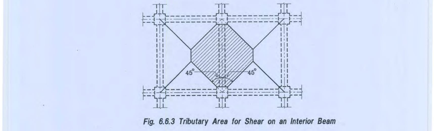
6.4.8 Reinforcement
6.4.8.1
Area of reinforcement in each direction for slab systems shall be determined from moments at critical sections but shall not be less than that required by Sec 8.1.12.6.4.8.2
Spacing of reinforcement at critical sections shall not exceed two times the slab thickness, except for portions of slab area that may be of cellular or ribbed construction. In the slab over cellular spaces, reinforcement shall be provided as required by Sec 8.1.12.6.4.8.3
Positive moment reinforcement perpendicular to a discontinuous edge shall extend to the edge of slab and have embedment, straight or hooked, at least 150 mm in spandrel beams, columns, or walls.6.4.8.4
Negative moment reinforcement perpendicular to a discontinuous edge shall be bent, hooked or otherwise anchored, in spandrel beams, columns, or walls, to be developed at face of support according to provisions of Sec 8.2.6.4.8.5
Where a slab is not supported by a spandrel beam or wall at a discontinuous edge, or where a slab cantilevers beyond the support, anchorage of reinforcement may be within the slab.6.4.8.6
In slabs with beams between supports with a value of greater than 1.0, special top and bottom slab reinforcement shall be provided at exterior corners in accordance with the following: a) The special reinforcement in both top and bottom of slab shall be sufficient to resist a moment equal to the maximum positive moment (per metre of width) in the slab. b) Direction of moment shall be assumed parallel to the diagonal from the corner in the top of the slab and perpendicular to the diagonal in the bottom of the slab. c) The special reinforcement shall be provided for a distance in each direction from the corner equal to one-fifth the longer span. d) In either the top or bottom of the slab, the special reinforcement may be placed in a single band in the direction of the moment or in two bands parallel to the sides of the slab.6.4.8.7 Details of Reinforcement in Slabs without Beams
a) In addition to the other requirements of this section, reinforcement in slabs without beams shall have minimum extensions as shown in Fig 6.6.4. b) Where adjacent spans are unequal, extensions of negative moment reinforcement beyond the face of support as shown in Fig 6.6.4 shall be based on requirements of the longer span. c) Bent bars may be used only when depth-span ratio permits use of bends 45 degrees or less. d) For slabs in frames not braced against side sway, lengths of reinforcement shall be determined by analysis but shall not be less than those prescribed in Fig 6.6.4. e) At least two of the column strip bottom bars in each direction shall be continuous or spliced at the support with Class A splices or anchored within support. These bars shall pass through the column and shall be placed within the column core.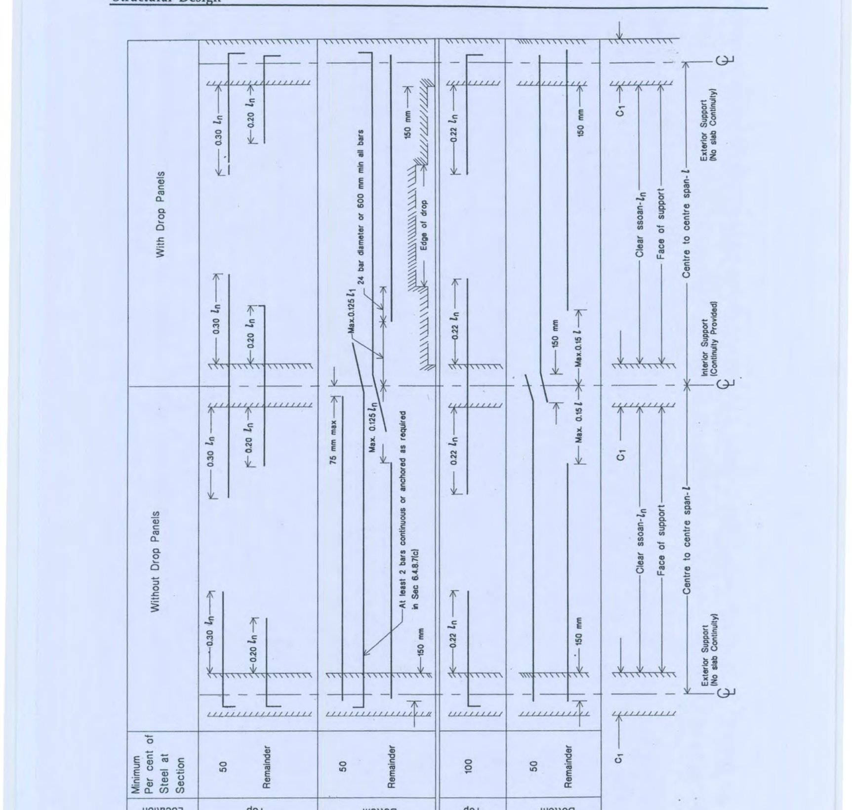
6.4.9 Openings
6.4.9.1
Openings of any size may be provided in slab systems if shown by analysis that the design strength is at least equal to the required strength and that specified limits on deflections are met.6.4.9.2
In lieu of special analysis as required by Sec 6.4.9.1 above, openings may be provided in slab systems only in accordance with the following: a) Openings of any size may be located in area common to intersecting middle strips, provided that the total amount of reinforcement required for the panel without the opening is maintained. b) In the area common to intersecting column strips, not more than one-eighth of the width of column strip in either span shall be interrupted by openings. An amount of reinforcement equivalent to that interrupted by an opening shall be added on the sides of the opening. c) In the area common to one column strip and one middle strip, not more than one-quarter of the reinforcement in either strip shall be interrupted by openings. An amount of reinforcement equivalent to that interrupted by an opening shall be added on the sides of the opening. d) When opening in slabs are located at a distance less than 10 times the slab thickness from a concentrated load or reaction area or when openings in slabs are located within column strip, the critical sections for shear defined in 6.4.7.1(b) and 6.4.7.4(g) shall be modified as follows: i) For slabs without shearheads, that part of the perimeter of the critical section that is enclosed by straight lines projecting from the centroid of the column, concentrated load or reaction area and tangent to the boundaries of the openings shall be considered ineffective. ii) For slabs with shearheads, the ineffective portion of the perimeter shall be one-half of that defined in (i) above.6.5 Alternative Design of Two-Way Edge-Supported Slabs
6.5.1 Notation
6.5.2 Scope and Limitations
6.5.2.1
The provisions of this section may be used as alternative to those of Sec 6.4 for two-way slabs supported on all four edges by walls, steel beams or monolithic concrete beams having a total depth not less than 3 times the slab thickness.6.5.2.2
Panels shall be rectangular with a ratio of longer to shorter span centre to centre of supports not greater than 2.6.5.2.3
The value of shall be greater than or equal to 1.6.5.3 Analysis by the Coefficient Method
6.5.3.1
The negative moments and dead load and live load positive moments in the two directions shall be computed from Tables 6.6.11, 6.6.12 and 6.6.13 respectively. Shear in the slab and loads on the supporting beams shall be computed from Table 6.6.14.6.5.4 Shear on Supporting Beam
The shear requirements provided in Sec 6.4.7.6 shall be satisfied.6.5.5 Deflection
Thickness of slabs supported on walls or stiff beams on all sides shall satisfy the requirements of Sec 6.4.3.1 (b) and (c). Table 6.6.11: Coefficients for Negative Moments in Slabs† where = total uniform dead plus live load per unit area The nine boundary-condition “Cases” referenced in Tables 6.6.11 through 6.6.14 are defined by the following panel edge-condition diagrams (a crosshatched edge indicates that the slab continues across, or is fixed at the support; an unmarked edge indicates a support at which torsional resistance is negligible):
† A crosshatched edge indicates that the slab continues across, or is fixed at the support; an unmarked edge indicates a support at which torsional resistance is negligible.
Table 6.6.12: Coefficients for Dead Load Positive Moments in Slabs†
where = uniform dead load per unit area
† A crosshatched edge indicates that the slab continues across, or is fixed at the support; an unmarked edge indicates a support at which torsional resistance is negligible.
Table 6.6.13: Coefficients for Live Load Positive Moments in Slabs†
where = uniform live load per unit area
The source table prints the value for ratio 0.55, Case 9 as “00.063” (an extra leading zero, evidently a printing artifact in the original gazette table). Transcribed here as 0.063.
† A crosshatched edge indicates that the slab continues across, or is fixed at the support; an unmarked edge indicates a support at which torsional resistance is negligible.
6.5.6 Reinforcement
6.5.6.1
Area of reinforcement in each direction shall be determined from moments at critical sections but shall not be less than that required by Sec 8.1.12.6.5.6.2
Spacing of reinforcement at critical sections shall not exceed two times the slab thickness, except for portions of slab area that may be of cellular or ribbed construction. In the slab over cellular spaces, reinforcement shall be provided as required by Sec 8.1.12.6.5.6.3
Positive moment reinforcement perpendicular to a discontinuous edge shall extend to the edge of slab and have embedment, straight or hooked, at least 150 mm in spandrel beams, columns, or walls.6.5.6.4
Negative moment reinforcement perpendicular to a discontinuous edge shall be bent, hooked, or otherwise anchored, in spandrel beams, columns, or walls, and shall be developed at face of support according to provisions of Sec 8.2.6.5.6.5 Corner Reinforcement
a) Special reinforcement shall be provided at exterior corners in both bottom and top of the slab, for a distance in each direction from the corner equal to one-fifth the longer span of the corner panel. b) Corner reinforcement at the top of the slab shall be parallel to a line bisecting the angle at the relevant corner. c) The corner reinforcement at the bottom of the slab shall be perpendicular to a line bisecting the angle at the relevant corner. d) The top and bottom corner reinforcement shall be of size and spacing equivalent to that required for the maximum positive moment in the panel.6.6 Ribbed and Hollow Slabs
6.6.1 General
The provisions of this section shall apply to slabs constructed in one of the ways described below: a) As a series of concrete ribs with topping cast on forms which may be removed after the concrete has set; b) As a series of concrete ribs between precast blocks which remain part of the completed structure; the top of the ribs may be connected by a topping of concrete of the same strength as that used in the ribs; and c) Slabs with a continuous top and bottom face but containing voids of rectangular, oval or other shape.6.6.2 Analysis and Design
Any method of analysis which satisfies equilibrium and compatibility requirements may be used for ribbed and hollow slabs. Approximate moments and shears in continuous one-way ribbed or hollow slabs may be obtained from Table 6.6.2 in Sec 6.2.5.2. For two-way slabs, the unified design approach specified in Sec 6.4 Flat Plates, Flat Slabs and Edge-supported Slabs, shall be used.6.6.3 Shear
6.6.3.1
When burnt tile or concrete tile fillers of material having the same strength as the specified strength of concrete in the ribbed and hollow slabs are used permanently, it is permitted to include the vertical shells of fillers in contact with the ribs for shear and negative-moment strength computations, provided adequate bond between the two can be ensured.6.6.3.2
Adequate shear strength of slabs shall be provided in accordance with the requirements of Sec 6.4.7. For one-way ribbed and hollow slab construction, contribution of concrete to shear strength is permitted to be 10 percent more than that specified in Sec 6.2.7. It is permitted to increase shear strength using shear reinforcement or by widening the ends of ribs.6.6.4 Deflection
The recommendations for deflection with respect to solid slabs may be applied to ribbed and hollow slab. Total depth of one-way ribbed and hollow slabs shall not be less than those required by Table 6.6.3 in Sec 6.2.10.2. For other slabs the provisions of Sec 6.4.3.1 shall apply.6.6.5 Size and Position of Ribs
In-situ-ribs shall be not less than 100 mm wide. They shall be spaced at centres not greater than 750 mm apart and their depth, excluding any topping, shall be not more than three and half times their width. Ribs shall be formed along each edge parallel to the span of one-way slabs.6.6.6 Reinforcement
The recommendations given in Sec 8.1.7 regarding maximum distance between bars apply to areas of solid concrete in this form of construction. The curtailment, anchorage and cover to reinforcement shall be as specified below: a) At least 50 per cent of the total main reinforcement shall be carried through the bottom on to the bearing and anchored in accordance with Sec 8.2.8. b) Where a slab, which is continuous over supports, has been designed as simply supported, reinforcement shall be provided over the support to control cracking. This reinforcement shall have a cross-sectional area of not less than one quarter of that required in the middle of the adjoining spans and shall extend at least one-tenth of the clear span into adjoining spans. c) In slabs with permanent blocks, the side cover to the reinforcement shall not be less than 10 mm. In all other cases, cover shall be provided according to Sec 8.1.8.6.7 Framed Structures
6.7.1 Scope
The provisions of this section shall apply to rigidly jointed RC framed structures subject to lateral loads in addition to gravity loads.6.7.2 Continuity
All intersections of members in a framed structure shall be continuous, with the steel reinforcements continued through the joints into the adjacent members to provide adequate development length. At construction joints, special care shall be taken to bond the new concrete to the old by carefully cleaning the latter, by extending the reinforcement through the joint and by other means.6.7.3 Placement of Loads
All individual members and joints of the framed structure shall be designed for the worst combination of factored loads as provided in Sec 1.4. Gravity live loads in different bays and in different storeys of a framed structure shall be so arranged as to produce the maximum moment and shear at all critical sections.6.7.4 Idealization
6.7.4.1
For the purpose of analysis, the members of the frame shall be represented by straight lines coincident with their centroidal axes. When the centroidal axes of the members meeting at a joint do not coincide at a single point, the effect of offset from the point representing the joint shall be taken into consideration.6.7.4.2
Use of any set of reasonable assumptions is permitted for computing relative flexural and torsional stiffness of columns, walls, floors, and roof systems. The assumptions adopted shall be consistent throughout the analysis.6.7.4.3
The moment of inertia of the frame members shall be based on the gross concrete cross section.6.7.4.4
Effect of haunches shall be considered both in determining moments and in the design of members.6.7.4.5
Columns having their bases monolithically cast in a substantial foundation, which may be anchored to a solid rock mass or supported on piles with their tops encased in pile cap, or which is a continuous raft or mat, may be assumed to be fixed at their bases. Otherwise, the column bases shall be assumed to permit rotation. In either case, the foundation shall be designed to resist any moment that may be transferred to it from the structure in view of the assumptions made and the detailing used at the base.6.7.5 Method of Analysis
6.7.5.1 Gravity Loads
For building frames with reasonably regular outline, not involving unusual asymmetry of loading or shape, moments due to gravity loads may be determined by dividing the entire frame into simpler sub-frames. Each sub-frame shall consist of one continuous beam, plus the top and bottom columns framing into that particular beam. The far ends of the columns, built integrally with the structure, shall be considered fixed. For the sub-frame at the bottom of the structure, the column end conditions at the base shall be dictated by the soil and foundation considerations in accordance with Sec 6.7.4.5 above. The arrangement of live load on the sub-frame may be limited to the combinations, (a) factored dead load on all spans with full factored live load on two adjacent spans, and (b) factored dead load on all spans with full factored live load on alternate spans. For building frames not satisfying the requirements above, a full frame analysis using elastic method shall be carried out for gravity loads.6.7.5.2 Lateral Loads
Any method of elastic analysis that satisfies equilibrium and compatibility requirements may be used for framed structures. Approximate methods that reduce the frame to a statically determinate structure by making simplifying assumptions shall not be used except for preliminary proportioning of sections for subsequent more accurate analysis.6.7.5.3 Redistribution of Negative Moments
Negative moments in continuous beams of a framed structure may be redistributed in accordance with Sec 6.2.5.3.6.7.6 Design
The frame members shall be designed for the factored shear, moment, torsion and axial force obtained from the elastic analysis. The critical section for design for negative moment in beams may be assumed to be at the face of the support.6.8 Deep Beams
6.8.1 Notation
6.8.2 General
6.8.2.1
Flexural members with clear span to overall depth ratios not greater than 2.5 for continuous spans, or 2.0 for simple spans, shall be designed as deep beams taking into account nonlinear distribution of strain and lateral buckling (See also Sec 8.2.7.6).6.8.2.2
Shear strength of deep beams shall be provided in accordance with Sec 6.8.4 below.6.8.2.3
Minimum flexural tension reinforcement shall conform to Sec 6.2.8.6.8.2.4
Minimum horizontal and vertical reinforcement in the side faces of deep beams shall satisfy the requirements of Sec 6.8.4.8, 6.8.4.9 and 6.8.4.10, below but the reinforcement shall not be less than that required for walls in Sec 6.9.7.2 and 6.9.7.3.6.8.3 Flexure
6.8.3.1
Deep beams shall be designed for flexure using Eq (6.2.2) except that the lever arm shall be replaced by . The lever arm, , shall be calculated as follows: a) For simply supported beams: or b) For continuous beams: or where is the effective span taken as centre to centre distance between supports or 1.15 times the clear span, whichever is smaller, and is the overall thickness.6.8.3.2
The tensile reinforcement required to resist positive bending moment in any span of deep beam shall extend without curtailment between supports and be embedded beyond the face of each support, so that at the face of support it shall have a development length in accordance with Sec 8.2. The positive reinforcement shall be placed within a zone of depth equal to adjacent to the tension face of the beam.6.8.3.3
The tensile reinforcement required to resist negative bending moment over a support of a deep beam shall be allowed to terminate not more than half of the reinforcement at a distance of from the face of the support and remainders shall be extend over the full span. When ratio of clear span to overall depth is in the range 1.0 to 2.5, tensile negative reinforcement over a support shall be placed in two zones comprising: i) a zone of depth , adjacent to the tension face, which shall contain a proportion of the steel given by . ii) a zone measuring on either side of the mid-depth of the beam, which shall contain the remainder of the tension steel, evenly distributed. For span to depth ratios less than unity, the steel shall be evenly distributed over a depth of measured from the tension face.6.8.4 Shear
6.8.4.1
The following provisions shall apply to members with less than 5 that are loaded on one face and supported on the opposite face so that compression struts can develop between the loads and the supports.6.8.4.2
The shear design of simply supported deep beams shall be based on Eq (6.2.14) and (6.2.15) where the shear strength shall be in accordance with Sec 6.8.4.6 or 6.8.4.7 below and the shear strength shall be in accordance with Sec 6.8.4.8 below.6.8.4.3
The shear design of continuous deep beams shall be based on Sec 6.2.7.1 through 6.2.7.5 or on any method which satisfies equilibrium compatibility and strength requirements. In either case the design shall also satisfy the requirements of Sec 6.8.4.4, 6.8.4.9 and 6.8.4.10.6.8.4.4
Nominal shear strength for deep beams shall be calculated by:6.8.4.5
Critical section for shear shall be taken at a distance of for uniformly loaded beams and for beams with concentrated loads, measured from the face of support, but in either case not greater than .6.8.4.6
Unless a more detailed calculation is made in accordance with Sec 6.8.4.7 below, shall be taken as6.8.4.7
may be computed more accurately taking into account the effects of and from except that the term shall not exceed 2.5 and shall not be taken greater than .6.8.4.8
Where factored shear force exceeds shear strength shear reinforcement shall be provided to satisfy Eq (6.2.14) and (6.2.15), where shear strength shall be computed by6.8.4.9
Area of shear reinforcement shall not be less than , and shall not exceed , nor 450 mm.6.8.4.10
The area of horizontal shear reinforcement shall not be less than and shall not exceed , nor 450 mm.6.8.4.11
Shear reinforcement required at the critical section defined in Sec 6.8.4.5 shall be used throughout the span.6.9 REINFORCED CONCRETE WALLS
6.9.1 Notation
6.9.2 General
6.9.2.1
Walls shall be designed for eccentric loads and any lateral or other loads to which they may be subjected.6.9.2.2
Walls subjected to axial load shall be designed in accordance with Sec 6.9.2, 6.9.7 and either 6.9.3 or 6.9.4 below.6.9.2.3
Design for shear shall be in accordance with Sec 6.9.6 below.6.9.2.4
Unless otherwise justified by a detailed analysis, horizontal length of wall to be considered effective for each concentrated load shall not exceed centre to centre distance between the loads, nor the width of bearing plus four times the wall thickness.6.9.2.5
Transfer of force to base of wall shall be in accordance with Sec 6.10.6.6.9.3 Empirical Design Method
6.9.3.1
Load bearing walls of solid rectangular cross-section may be designed by the empirical method if the resultant of all factored loads is located within the middle-third of the overall thickness of wall and all the requirements of Sec 6.9.2, 6.9.3 and 6.9.7 are satisfied.6.9.3.2
Unless designed in accordance with Sec 6.9.4, the design axial load carrying capacity of a wall may be computed by Eq (6.9.1). where , and for walls restrained against rotation at one or both ends, for walls unrestrained at both ends, and for walls not braced against lateral translation.6.9.3.3 Minimum Thickness of Walls
a) The thickness of load bearing walls shall not be less than of the supported height or length, whichever is shorter, nor less than 125 mm. b) The thickness of exterior basement walls and foundation walls shall not be less than 200 mm.6.9.4 Walls Designed as Compression Members
Walls subject to flexure or both flexure and axial compression shall be designed as compression members in accordance with the provisions of Sec 6.3, 6.9.2 and 6.9.7, except when designed in accordance with Sec 6.9.3.6.9.5 Walls as Grade Beams
6.9.5.1
Walls designed as grade beams shall have top and bottom reinforcement as required for moment in accordance with the provisions of Sec 6.2. Design for shear shall be in accordance with Sec 6.9.6 below.6.9.5.2
Portions of grade beam walls exposed above grade shall also meet the requirements of Sec 6.9.7.6.9.6 Shear
6.9.6.1
Design for shear forces perpendicular to face of wall shall be in accordance with provisions for slabs in Sec 6.4.7. Design for horizontal shear forces in plane of wall shall be in accordance with Sec 6.9.6.2 through 6.9.6.8 below.6.9.6.2
Design of horizontal section for shear in plane of wall shall be based on Eq (6.2.14) and (6.2.15), where shear strength shall be in accordance with Sec 6.9.6.5 or 6.9.6.6 below and shear strength shall be in accordance with Sec 6.9.6.9 below.6.9.6.3
Nominal shear strength at any horizontal section for shear in plane of wall shall not be taken greater than .6.9.6.4
For the design of shear wall, shall be taken equal to . A larger value of , equal to the distance from extreme compression fibre to centre of force of all reinforcement in tension may be used when determined by a strain compatibility analysis.6.9.6.5
Unless a more detailed calculation is made in accordance with Sec 6.9.6.6 below, shear strength shall not be taken greater than for walls subjected to in compression, or shall not be taken greater than the value given in Sec 6.2.7.3(b)iii for walls subjected to in tension.6.9.6.6
Shear strength may be computed by Eq (6.9.2) and (6.9.3) and shall be taken as the smaller of the two. or where is negative for tension. When is negative, Eq (6.9.3) shall not apply.6.9.6.7
Sections located closer to wall base than a distance or one-half the wall height, whichever is less, may be designed for the same as that computed at a distance or one-half the height.6.9.6.8
When factored shear force is less than , reinforcement shall be provided in accordance with Sec 6.9.6.9 or 6.9.7. When exceeds , wall reinforcement for resisting shear shall be provided in accordance with Sec 6.9.6.9.6.9.6.9 Design of Shear Reinforcement
a) Where factored shear force exceeds shear strength , horizontal shear reinforcement shall be provided to satisfy Eq (6.2.14) and (6.2.15), where shear strength shall be computed by where is the area of horizontal shear reinforcement within a distance and distance is in accordance with Sec 6.9.6.4. Vertical shear reinforcement shall be provided in accordance with (c) below. b) Ratio of horizontal shear steel to gross concrete area of vertical section shall not be less than 0.0025, and spacing of horizontal shear reinforcement shall not exceed , or 450 mm. c) Ratio of vertical shear steel to gross concrete area of horizontal section shall not be less than but not less than 0.0025. The vertical steel ratio need not be greater than the required horizontal steel ratio. The spacing of vertical shear reinforcement shall not exceed , or 450 mm.6.9.7 Minimum Reinforcement
6.9.7.1
Minimum vertical and horizontal reinforcement shall be in accordance with Sec 6.9.7.2 and 6.9.7.3 below, unless a greater amount is required for shear by Sec 6.9.6.8 and 6.9.6.9 above.6.9.7.2
Minimum ratio of vertical reinforcement area to gross concrete area shall be: a) 0.0012 for deformed bars not larger than 16 mm with a specified yield strength not less than 410 N/mm², or b) 0.0015 for other bars.6.9.7.3
Minimum ratio of horizontal reinforcement area to gross concrete area shall be: a) 0.0020 for deformed bars not larger than 16 mm with a specified yield strength not less than 410 N/mm², or b) 0.0025 for other bars.6.9.7.4
Walls more than 250 mm thick shall have reinforcement for each direction placed in two layers parallel to the faces of wall, except basement wall, in accordance with the following: a) One layer consisting of not less than one-half and not more than two-thirds of total reinforcement required for each direction. The reinforcement shall be placed not less than 50 mm nor more than one-third thickness of wall from exterior surface. b) The other layer, consisting of the balance of required reinforcement in that direction, shall be placed not less than 20 mm nor more than one-third the thickness of wall from interior surface.6.9.7.5
Vertical and horizontal reinforcement shall not be spaced farther apart than three times the wall thickness nor 450 mm.6.9.7.6
If vertical reinforcement area is not greater than 1 percent of the gross concrete area, or where vertical reinforcement is not required as compression reinforcement, vertical reinforcement need not be enclosed by lateral ties.6.9.7.7
At least two 16 mm bars shall be provided around all window and door openings in addition to the minimum reinforcement. Such bars shall be extended beyond the corners of the openings by at least 600 mm.6.10 Footings
6.10.1 Notation
6.10.2 General
6.10.2.1
When a footing or pile cap is concentrically loaded, the reactions to design factored loads may be assumed to be uniformly distributed (i.e. load per unit area or per pile).6.10.2.2
When a footing or a pile cap is eccentrically loaded, the reactions may be assumed to vary linearly across the footing or across the pile system.6.10.2.3
Base area of footing shall be determined from unfactored forces and moments transmitted by footing to soil.6.10.2.4
Number and arrangement of piles shall be determined for unfactored forces and moments from permissible soil pressure or permissible pile capacity selected through principles of soil mechanics.6.10.2.5
It is permissible to treat circular or regular polygon shaped concrete columns as square members with the same area, for location of critical sections for moment, shear and development of reinforcement in footings.6.10.2.6
Footings shall be designed to resist the factored loads and induced reactions, in accordance with the appropriate design requirements as provided in this section.6.10.2.7
Depth of footing above bottom reinforcement shall not be less than (i) 150 mm for footings on soil, and (ii) 300 mm for footings on piles.6.10.2.8
Plain concrete footings on piles are not permitted.6.10.3 Moment
6.10.3.1
External moment on any section of a footing shall be determined by passing a vertical plane through the footing, and computing the moment of the forces acting over the area of footing on one side of vertical plane.6.10.3.2
Maximum factored moment for an isolated footing shall be computed at critical sections located as follows: a) For footings supporting a concrete column, pedestal or wall, at face of column, pedestal, or wall. b) For footings supporting a masonry wall, at a quarter thickness inside the wall. c) For footings supporting a column with steel base plate, at halfway between the face of column and the edge of steel base plate.6.10.3.3
In one-way footings and two-way square footings, reinforcement shall be distributed uniformly across the entire footing.6.10.3.4
In two-way rectangular footings, reinforcement shall be distributed as follows: a) Reinforcement in long-direction shall be distributed uniformly across the entire width of footing. b) For reinforcement in short direction, a portion of the total reinforcement given by Eq (6.10.1) shall be distributed uniformly over a band width (centred on centre-line of column or pedestal) equal to the length of short side of footing. Remainder of the reinforcement required in the short direction shall be distributed uniformly outside the centre band width of footing.6.10.4 Shear
6.10.4.1
Shear strength of footings in the vicinity of columns or walls is governed by the more severe of the following conditions. a) Beam action shall be investigated at each critical section extending in a plane across the entire width. For beam action, the footing shall be designed in accordance with Sec 6.2.7.1 through 6.2.7.5. b) Location of critical section for shear in beam action shall be at a distance measured from face of column, pedestal or wall, for footings supporting a column, pedestal or wall. For footings supporting a column or pedestal with steel base plates, the critical section shall be measured from locations defined in Sec 6.10.3.2(c) above. c) Two-way action shall be investigated at the critical section located so that its perimeter is a minimum but need not approach closer than to edges of columns or walls. For two-way action the footing shall be designed in accordance with Sec 6.10.4.2 and 6.10.4.3 below. d) For square or rectangular columns, the critical sections for two-way action shall have four straight sides.6.10.4.2
Unless shear reinforcement is provided, the factored shear force shall be equal to or less than the shear strength, , carried by the concrete. The shear strength shall be determined as follows: i) One-way shear: For one-way shear, shall be computed either by using the approximate relation: or by the more detailed formula: ii) Two-way shear: For two-way shear, shall be determined in accordance with Sec 6.4.7.2.6.10.4.3
Shear reinforcement consisting of bars or wires is permitted in footings in accordance with the following: a) shall be computed by Eq (6.2.15) where shall not be taken greater than , and the required area of shear reinforcement and shall be calculated in accordance with Sec 6.2.7.4 and anchored in accordance with Sec 8.2.10. b) shall not be taken greater than .6.10.5 Development of Reinforcement
6.10.5.1
Tension in the reinforcement shall be developed on each side of the critical section for moment.6.10.5.2
Calculated tension or compression in reinforcement at each section shall be developed on each side of that section by embedment length, standard hook (tension only) or mechanical device, or a combination thereof.6.10.6 Transfer of Force at Base
6.10.6.1
When the loaded area (area of column pier or base plate) and the supporting area (area at the top of the footing) are equal, bearing stress on the loaded area of the footing shall be equal to or less than where is the lower of the strengths of footing or column concrete.6.10.6.2
When the supporting area is larger than the loaded area on all sides, the bearing stress on the loaded area shall be equal to or less than , but not greater than where = area of the lower base of the largest frustum of a pyramid, cone, or tapered wedge contained wholly within the footing and having for its upper base, the area actually loaded, and having side slopes of 1 vertical to 2 horizontal, and = loaded area at the column base.6.10.6.3
Where the stress on the loaded area exceeds the permissible bearing stress reinforcement shall be provided for the excess by extending the longitudinal bars into the footing or by dowels.6.10.6.4
Where transfer of force is accomplished by reinforcement, the development length of the reinforcement shall be sufficient to transfer the compression or tension to the supporting member in accordance with Sec 8.2.6.10.6.5
Extended longitudinal bars or dowels shall have a total area of at least 0.005 times the loaded area of the column or pedestal, and a minimum of four bars shall be provided. Where dowels are used, their diameter shall not exceed the diameter of the column bars by more than 3 mm.6.10.6.6
Column bars of diameters larger than 40 mm in compression only may be lap spliced with dowels not larger than 35 mm of the necessary area. The dowel shall extend into the column, a distance equal to the development length of the column bar and into the footing a distance equal to the development length of the dowel.6.10.7 Sloped or Stepped Footings
6.10.7.1
Angle of slope or depth and location of steps in sloped or stepped footings, shall be such that all design requirements are satisfied at every section (See also Sec 8.2.7.6).6.10.7.2
Sloped or stepped footings designed as a unit shall be constructed to assure action as a unit.6.10.8 Combined Footings and Mats
6.10.8.1
Footings supporting more than one column, pedestal or wall (combined footings or mats) shall be designed to resist the factored loads and induced reactions, in accordance with the Sec 6.2.6 and 6.4.7.6.10.8.2
The Direct Design Method of Sec 6.4.5 shall not be used for the design of combined footings and mats.6.10.8.3
Distribution of soil pressure under combined footings and mats shall be consistent with the properties of soil and structure and with established principles of soil mechanics.6.10.9 Pile Caps
6.10.9.1
Pile caps shall be designed either by bending theory or by truss analogy.6.10.9.2 Truss Analogy Method
a) When truss method is used, the truss shall be of triangulated form, with a node at the centre of loaded area. The lower nodes of the truss shall lie at the intersections of the centre lines of the piles with the tensile reinforcement. b) Where the truss method is used with widely spaced piles (spacing exceeding three times the pile diameter), only the reinforcement within a band width of 1.5 times the pile diameter from the centre of a pile shall be considered to constitute a tension member of the truss.6.10.9.3
Beam shear in pile cap shall be checked at critical sections extending across the full width of the cap. Critical sections shall be assumed to be located at 20% of the diameter of the pile inside the face of the pile, as indicated in Fig 6.6.5. The total force from all the piles with centres lying outside this line shall be considered to constitute the shear force on this section.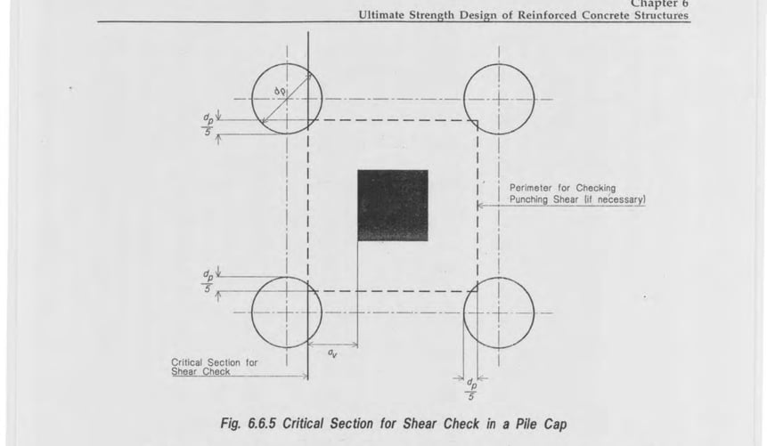
6.10.9.4 Punching Shear
A check shall be made to ensure that the factored shear stress calculated at the perimeter of the column does not exceed or 5 N/mm², whichever is the smaller. In addition, if the spacing of the piles is greater than 3 times the pile diameter, punching shear shall be checked on the perimeter indicated in Fig 6.6.5, in accordance with Sec 6.4.7.6.10.9.5 Anchorage
The tension reinforcement shall be provided with full anchorage in accordance with Sec 8.2.6.11 Stairs
6.11.1 Effective Span
The effective span of stairs without stringer beams shall be taken as the following horizontal distances: a) Centre to centre distance of beams, where supported at top and bottom risers by beams spanning parallel with the risers, b) Where supported at the edge of a landing slab, which spans parallel with the risers, (Fig 6.6.6a) a distance equal to the going of the stairs plus at each end either half the width of the landing or 1.0 m whichever is smaller. The going shall be measured horizontally. c) Where the landing spans in the same direction as the stairs (Fig 6.6.6b), the span shall be the distance centre to centre of the supporting beams or walls. d) Where the landing slab, running at right angles to the direction of the flight, is supported by walls or beams on three sides (Fig 6.6.6c), the effective span shall be the going of the stair measured horizontally. Both positive and negative moments per unit width of the stair shall be calculated as where is the intensity of the total factored dead and live load per unit area on a horizontal plane.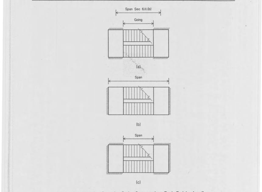
6.11.2 Loading
Staircases shall be designed to support the design ultimate load according to the load combinations specified in Chapter 2, loads.6.11.3 Distribution of Loading
6.11.3.1
Where flights or landing are embedded at least 110 mm into walls and are designed to span in the direction of the flight, a 150 mm strip may be deducted from the loaded area and the effective breadth of the section may be increased by 75 mm for the purpose of design (Fig 6.6.7).
6.11.3.2
In the case of stairs with open wells, where spans cross at right angles, the load on areas common to any two such spans may be taken as one half in each direction as shown in Fig 6.6.8.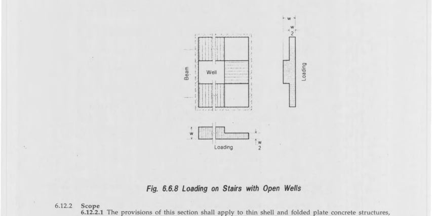
6.11.4 Depth of Section
The depth of the section shall be taken as the minimum thickness perpendicular to the soffit of the staircase.6.11.5 Design
6.11.5.1 Strength, Deflection and Crack Control
The recommendations given in Sec 6.2 for beams and one-way slabs shall apply, except for the span/depth ratio of staircases without stringer beam where the provision of Sec 6.11.5.2 below shall apply.6.11.5.2
Permissible span/effective depth ratio for staircase without stringer beams. Provided the stair flight occupies at least 60% of the span, the ratio calculated in accordance with Sec 6.2.10 shall be increased by 15%.6.12 Shells and Folded Plates
6.12.1 Notation
6.12.2 Scope
6.12.2.1
The provisions of this section shall apply to thin shell and folded plate concrete structures, including ribs and edge members.6.12.2.2
Other provisions of Chapter 6 not specifically excluded, and not in conflict with the provisions of this section shall apply to thin shell structures.6.12.3 Definitions
ANALYSIS, APPROXIMATE: A method not satisfying compatibility of strains either within the shell or between the shell and the auxiliary members. It may be used only where it can be shown that this method provides a safe basis for design. ANALYSIS, ELASTIC: An analysis based on equilibrium, compatibility of strains, and assumed elastic behaviour. The analysis shall represent to suitable approximation the three dimensional action of the shell together with its auxiliary members. ANALYSIS, EXPERIMENTAL: An analysis based on the measurement of deformations and/or strains of the structure or its model. Experimental analysis is based on either elastic or inelastic behavior. ANALYSIS, INELASTIC: An analysis based on equilibrium, nonlinear stress-strain relations for concrete and reinforcement, consideration of cracking and time dependent effects, and compatibility of strains. The analysis shall represent to suitable approximation the three-dimensional action of the shell together with its auxiliary members. AUXILIARY MEMBERS: Ribs or edge beams which strengthen, stiffen, and/or support the shell. Auxiliary members normally act jointly with the shell. FOLDED PLATES: A special class of shell structures made up by joining flat, thin slabs along their edges so as to create a three-dimensional space structure. RIBBED SHELLS: Space structures strengthened primarily along certain preferred rib lines, with the area between the ribs filled with thin slabs or left open. THIN SHELLS: Three-dimensional space structures consisting of one or more curved slabs or folded plates where thicknesses are small compared to other dimensions. Thin shells are characterized by their three-dimensional load-carrying behaviour which depends on the geometry of their form, by the way in which they are supported, and by the nature of the applied load.6.12.4 Design
6.12.4.1
Elastic behaviour shall be an accepted basis for determining internal forces and displacements of thin shells. Such an elastic analysis shall be based on the assumption of uncracked concrete section in which the material is assumed linearly elastic, homogeneous, and isotropic. Poisson’s ratio of concrete may be assumed equal to zero.6.12.4.2
Experimental or numerical analytical procedure and inelastic analysis may be used where it can be shown that such methods provide a safe basis for design.6.12.4.3
Equilibrium checks of internal resistance and external loads shall be made to ensure consistency of results.6.12.4.4
The thickness of a thin shell and its reinforcement, shall be determined for the required strength and serviceability. All elements shall be proportioned by the same method using the provisions of this chapter.6.12.4.5
Shell design shall investigate and exclude the possibility of general or local instability.6.12.4.6
Auxiliary members shall be designed according to the applicable provisions of this chapter. The same design method selected for shell elements shall be used for auxiliary members. A portion of the shell equal to the flange width of a T-beam may be assumed to act with the auxiliary member. In such portions of the shell, the reinforcement perpendicular to the auxiliary member shall be at least equal to that required for the flange of a T-beam.6.12.5 Strength of Material
6.12.5.1
Specified compressive strength of concrete at 28 days shall not be less than 20 N/mm².6.12.5.2
Maximum yield strength of reinforcement shall be 410 N/mm².6.12.6 Shell Reinforcement
6.12.6.1
Shell reinforcement shall be provided to resist bending and twisting moments, to resist tensile stresses from internal membrane forces, to control shrinkage and temperature cracking, and as special reinforcement at shell boundaries, load attachments and shell openings.6.12.6.2
Membrane reinforcement shall be provided in all parts of the shell in two or more directions.6.12.6.3
The area of shell reinforcement provided in two orthogonal directions shall not be less than the slab shrinkage or temperature reinforcement required by Sec 8.1.12.6.12.6.4
Reinforcement required to resist shell membrane forces shall be provided so that the design strength in every direction shall be at least equal to the component of the principal membrane forces in the same direction due to factored loads.6.12.6.5
The area of shell tension reinforcement shall be limited so that the reinforcement yields before crushing of concrete.6.12.6.6
In regions of high tension, membrane reinforcement shall be placed in the general directions of the principal tensile membrane forces, if possible. Where this is not possible, it is permitted to place membrane reinforcement in two orthogonal directions.6.12.6.7
The amount of reinforcement shall be increased to limit the width of possible cracks at service load levels, when direction of reinforcement varies more than 10 deg from the direction of principal tensile membrane force.6.12.6.8
The ratio of shell reinforcement in any portion of the tensile zone shall be not less than 0.0035 based on the overall thickness of the shell. Reinforcement resisting the total tension shall be concentrated in the regions of largest tensile stress, where the magnitude of the principal tensile membrane stress within the shell varies greatly over the area of the shell surface.6.12.6.9
Reinforcement required to resist shell bending moments shall be provided with due regard to the simultaneous action of membrane axial forces at the same location. Where shell reinforcement is required in only one face to resist bending moments, equal amounts shall be placed near both surfaces of the shell even though a reversal of bending moments is not indicated by the analysis.6.12.6.10
Shell reinforcement in any direction shall not be spaced farther apart than 450 mm nor five times the shell thickness. Reinforcement shall not be spaced farther apart than three times the shell thickness, where the principal membrane tensile stress on the gross concrete area due to factored loads exceeds .6.12.6.11
The minimum development length for shell reinforcement shall be but not less than 450 mm. Shell reinforcement at the junction of the shell and the supporting members or edge members shall be anchored in or extended through such members in accordance with the requirements of Sec 8.2.6.12.6.12
The minimum splice length of shell tension bars shall be 1.2 times the value required by Sec 8.2, but not less than 450 mm. The number of splices in principal tensile reinforcement shall be kept to a practical minimum. Where splices are necessary they shall be staggered at least with not more than one-third of the reinforcement spliced at any section.6.12.7 Construction
6.12.7.1
Regarding deflection considerations, when removal of formwork is based on a specific modulus of elasticity of concrete , the value of shall be determined from flexural tests of field-cured beam specimens. The number of test specimens, the dimensions of test beam specimens, and test procedures shall be specified by the engineer.6.12.7.2
If construction results in deviations from the shape greater than the tolerances specified by the engineer, an analysis of the effect of the deviations shall be made and any required remedial actions shall be taken to ensure safe behaviour.6.13 Precast and Composite Construction
6.13.1 Notation
6.13.2 General
6.13.2.1
Individual elements of a member shall be investigated for all critical stages of loading.6.13.2.2
Properties of the individual elements or the most critical values shall be used in design when the specified strength, unit mass, or other properties of the various elements are different.6.13.2.3
No distinction shall be made between shored and unshored members for the strength computations of composite members.6.13.2.4
All elements shall be designed to support all loads introduced prior to full development of design strength of composite members.6.13.2.5
Reinforcement shall be provided to control cracking and to prevent separation of individual elements of composite members.6.13.2.6
Deflection limitations for composite members shall be in accordance with Sec 6.13.7.6.13.2.7
Shoring shall not be removed until supported elements have developed design properties required to support all the loads and to limit deflections and cracking at the time of removal of shoring.6.13.3 Design
6.13.3.1
Precast members shall be designed considering all loading and restraint conditions from the initial fabrication to the completion of the structure, including form removal, storage, transportation, and erection.6.13.3.2
Effects of all interconnected and adjoining details shall be considered to assure proper performance of the structural system, when precast members do not behave monolithically.6.13.3.3
Effects of initial and long-time deflections shall be considered for precast and composite members, including effects on interconnected elements.6.13.3.4
Design of joints and bearings shall include the effects of all forces to be transmitted, including shrinkage, creep, temperature, elastic deformation, wind, and earthquake.6.13.3.5
Proper detailing of members shall be done considering manufacturing and erection tolerances and temporary erection stresses.6.13.3.6
Where precast wall panels are designed to span horizontally to columns or isolated footings, the ratio of height to thickness shall not be limited, provided the effect of deep beam action, lateral buckling, and deflections are considered in the design.6.13.3.7
When an entire composite member is assumed to resist vertical shear, design shall be made in accordance with the requirements of Sec 6.2.7 as for a monolithically cast member of the same cross-sectional shape.6.13.3.8
For composite members, shear reinforcement shall be fully anchored into interconnected elements in accordance with Sec 8.2.10.6.13.3.9
Extended and anchored shear reinforcement provided in a composite member may be included as ties for horizontal shear.6.13.3.10
Full transfer of horizontal shear forces shall be assured at contact surfaces of interconnected elements in a composite member.6.13.3.11
Unless calculated in accordance with Sec 6.13.3.12 horizontal shear design shall be based on where is the factored shear force at the section considered, and is the nominal horizontal shear strength in accordance with the following: a) shall not be taken greater than , when contact surfaces are clean, free of laitance, and intentionally roughened, or when minimum ties are provided in accordance with Sec 6.13.3.14 and contact surfaces are clean and free of laitance, but not intentionally roughened. b) shall not be taken greater than , when minimum ties are provided in accordance with Sec 6.13.3.14 and contact surfaces are clean, free of laitance, intentionally roughened to a full amplitude of approximately 5 mm. c) When the factored shear force at section considered exceeds , design for horizontal shear shall be in accordance with Sec 6.13.3.15.6.13.3.12
Horizontal shear may be determined by computing the actual change in compressive or tensile force in any segment, and provisions shall be made to transfer that force as horizontal shear to the supporting element. The factored horizontal shear force shall not exceed horizontal shear strength as given above in Sec 6.13.3.11(a) through (c) where the area of contact surface shall be substituted for .6.13.3.13
When tension exists across any contact surface between interconnected elements, shear transfer by contact may be assumed only when minimum ties are provided in accordance with Sec 6.13.3.14.6.13.3.14 Ties for Horizontal Shear
a) When ties are provided to transfer horizontal shear, area of tie reinforcement shall not be less than that required by Sec 6.2.7.4(e) and tie spacing shall not exceed four times the least dimension of the supported element, nor 600 mm. b) Ties for horizontal shear may consist of single bars or wire, or multiple leg stirrups. c) All ties for horizontal shear shall be fully anchored into interconnected elements in accordance with Sec 8.2.10.6.13.3.15 Shear-Friction
a) The provisions of shear friction are to be applied where it is appropriate to consider shear transfer across a plane in structural concrete, such as an existing or potential crack, an interface between dissimilar materials, or an interface between concrete cast at different times. b) Members subject to shear transfer as described above shall be designed based on Eq (6.2.14), where is calculated in accordance with the provisions of (c) or (d) below. c) A crack shall be assumed to occur along the shear plane considered. The required area of shear-friction reinforcement crossing the shear plane shall be designed using the provision of (d) below, or alternatively, using any shear friction design methods that can predict the strength in good agreement with results of comprehensive tests. d) Shear-Friction Design Method i) When the shear-friction reinforcement is perpendicular to the shear plane, shear strength shall be computed by where is the coefficient of friction specified in (iii) below. ii) When the shear-friction reinforcement is inclined to the shear plane, such that the shear force produces tension in that reinforcement, the shear strength shall be computed by where is the angle between shear-friction reinforcement and shear plane. iii) The coefficient of friction used in Eq (6.13.2) and (6.13.3) shall be
e) Nominal shear strength shall not be taken greater than nor in Newtons, where is the area of concrete section resisting shear transfer.
f) Yield strength of shear-friction reinforcement for design purpose shall not exceed 410 N/mm².
g) Net tension across shear plane shall be resisted by additional reinforcement in excess to that provided for shear transfer. Permanent net compression across shear plane may be taken as additive to the force in the shear-friction reinforcement , when calculating the required .
h) Shear-friction reinforcement shall be uniformly distributed along the shear plane, if no moment acts across the shear plane. If a moment acts, the reinforcement shall be distributed primarily in the flexural tension zone and shall be anchored to develop the specified yield strength on both sides by embedment, hooks, or welding to special devices.
j) When concrete is placed against previously hardened concrete, the interface for shear transfer shall be clean and free of laitance. If is assumed equal to 1.0, interface shall be roughened to a full amplitude of approximately 5 mm.
k) When shear is transferred between as-rolled steel and concrete using headed studs or welded reinforcing bars, steel shall be clean and free of paint.
The source numbers the sub-items of Sec 6.13.3.15 a) through k), skipping the letter “i” (to avoid confusion with the roman numeral “i” used for the sub-items of d) above). This is preserved as it appears in the original gazette text.