
4.1 Scope
The purpose of including this Chapter in the Code is to enhance the design and construction of buildings through the use of building concepts having a positive environmental impact and encourage sustainable construction practices, allowing efficiency and conservation of energy, water and building materials, and to promote resource efficiency. In addition to the clauses stipulated here, all Codes and standards relevant to a building occupancy as set forth in other Sections of this Code will be applicable during implementation. Design and drawings will be submitted to indicate the location, nature and scope of the proposed energy efficient/sustainable feature. These shall indicate compliance to the provisions of this Code, and will be supplied by the relevant design professionals, e.g. electrical engineers, mechanical engineers, plumbing engineers, etc., supporting architectural drawings.4.1.1 Rationale for Sustainable/Green Buildings
Climate change is an established phenomenon affecting the environment globally and it is recognized that buildings and the built environment play a vital role in the process, impacting on the natural environment and the quality of life. Sustainable development concepts and approaches applied to the design, construction and operation of buildings or to any built environment can enhance both the economic and environmental benefits of the community in Bangladesh and around the world. Energy efficiency and sustainability is not an individual issue rather an integrated and inseparable part of the building design and construction process. The benefits of sustainable design principles include resource and energy efficiency, healthy buildings and materials, ecologically and socially sensitive land use and strengthened local economics and the communities, objectives vital for future development of Bangladesh.4.2 Definitions
4.3 Site Sustainability
This Section deals with sites to ensure energy efficiency through passive and low energy architectural features and management of resources.4.3.1 Mandatory Unpaved Area
Fifty (50) percent of mandatory open space shall be permeable on sites of all occupancy categories. The permeable area shall not remain bare generating dust, but will have green cover or be treated with perforated paving (≥ 50%), organic mulch, charcoal, etc.4.3.2 Site Drainage and Run-Off Coefficient
Designs shall indicate site drainage considerations along with flash flooding and erosion prevention measures for sites above 1340 m2 in area. As excessive paving is largely responsible for fast water run-off and flash flooding, design shall indicate measures taken to make paving permeable. The net run-off from a site shall be a maximum of sixty (60) percent. The following method will be used for the calculations, in conjunction with Table 3.4.1: Where, , , etc., being the areas of various surfaces, e.g. Pavements, roads, vegetation, etc., with different run-off coefficients , , etc., shown in the Table 3.4.1.4.3.3 Vegetation Plan
For sites above three (3) acres, it is mandatory for a vegetation plan to be submitted along with the site plan and Irrigation Plan, where priority shall be given to native plants in the selection for planting.4.3.4 Irrigation Plan
4.3.4.1
For sites above ten (10) acres, an irrigation plan with construction details shall be submitted with the site plan, where considerations shall include for management of rainwater.4.3.4.2
For these sites a retention pond of ≥ 3% of site area shall be provided. This shall include any existing natural water body within the site. Table 3.4.1: Run-Off Coefficients of Various Surfaces4.3.5 Rain Water Harvesting System
4.3.5.1
Buildings of total floor area > 4000 m2 shall have its own rain water harvesting system as discussed in Chapter 7 Part 8 and installed complying with Section 7.13 Part 8, of this Code. The reservoir capacity shall be a multiple of the area of Ground Coverage of the building and a rain collection coefficient of 0.073.4.3.5.2
The rainwater reservoir may be placed under the roof or at lower levels, including underground.4.4 BUILDING ENVELOPE
4.4.1 Window to Wall Ratio
4.4.1.1
For mechanically ventilated and cooled buildings of all occupancies, other than Hazardous and Storage, the Window to Wall ratio of building (WWRB), will be determined in conjunction with the glazing performance, as indicated by the Solar Heat Gain Coefficient (SHGC) or Shading Coefficient (SC) of the glass used. The relationship is given in Figure 3.4.1 and Table 3.4.2.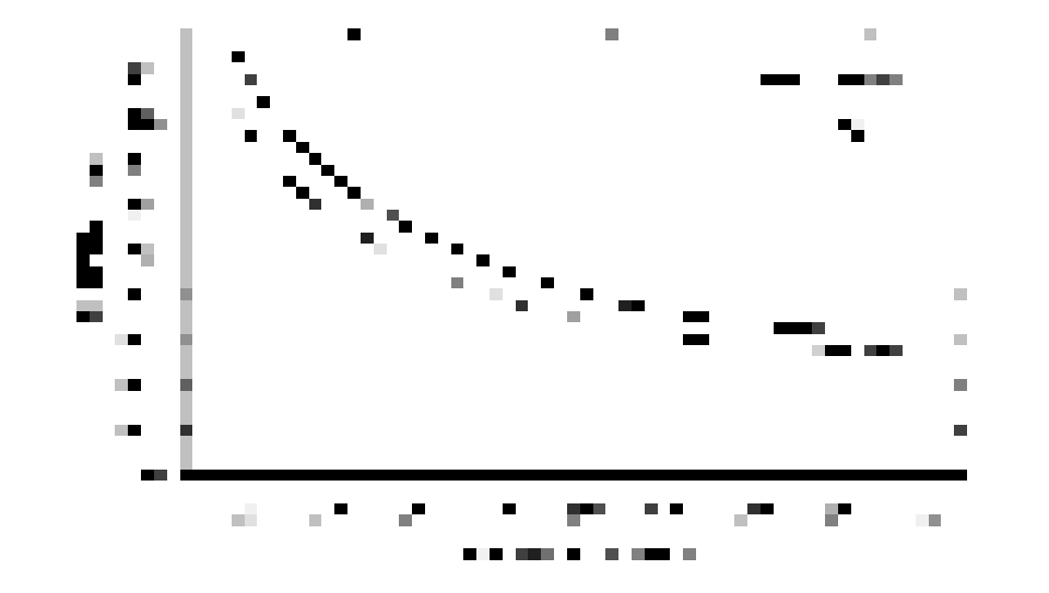
Figure 3.4.1 Selection of glazing SHGC based on WWR
4.4.1.2
In all of the above cases, the Visible Light Transmittance (VLT) of the glazed element shall not be lower than thirty five (35) percent.4.4.1.3
For Air-conditioned buildings with external shading, permitted SGHC limit may be adjusted, but the increase shall not exceed values determined by Eq. 3.4.2 below: Where, is the adjusted solar heat gain coefficient limit for windows with shading is the solar heat gain coefficient from Table 3.4.2 is the SHGC correction factor for the external shading as per Table 3.4.3 or Table 3.4.4: For a window with overhang and fin, the value of can be only used either from overhang or from fin.4.4.1.4
For naturally ventilated buildings, window size shall be based on Sec 4.4.2. Window Openings of this Code and shading shall be provided as per Sec 4.4.3.4.4.1.5
Window size shall under no circumstances be less than as stipulated under Part 3: Chapter 1, Section 1.17 of this Code. Table 3.4.3: Correction Factor against Overhang Shading Projection Factor
Table 3.4.4: Correction Factor against Vertical Shading (fins) Projection Factor
4.4.2 Window Openings
Mechanically ventilated and cooled buildings of all occupancies, other than hazardous, retail and storage, shall have the provision of using natural ventilation for cooling and fresh air, in frequently occupied areas , with a fraction ≥ 4% of the floor area being specified as openable windows. Openable balcony doors can be counted in this calculation. Note if the window area defined under Sec 4.4.1 is less than openable area, then fifty (50) percent of window area should be openable.4.4.2.1
Naturally ventilated buildings of all occupancies, other than hazardous and storage, shall provide for fifty (50) percent of its window area to be openable.4.4.2.2
All the openable windows above ground should be designed with safety measures in place such as protection hand rails for child safety.4.4.2.3
Windows to any regularly occupied space on exterior walls in naturally ventilated buildings shall be shaded conforming to Sec 4.4.3.4.4.3 Shading
4.4.3.1
For naturally ventilated buildings of all occupancies, horizontal sunshades shall be provided over windows on South, East and West, the depth of which shall be calculated by multiplying the window height with a factor of 0.234 (Figure 3.4.2). Horizontal louvers can be used instead of sunshades, in which case, depth of louver shall not be less than 0.234 times the gaps between the louvers (Figure 3.4.3).4.4.3.2
Vertical Shading devices shall be provided on the West, depth of which shall be calculated, by multiplying the gaps between the vertical fins, or the window width if the shades border the window width, with a factor of 0.234 (Figure 3.4.4). Exceptions:- (a) The above rule shall be relaxed if it can be demonstrated that shading is achieved by existing neighbouring structures.
- (b) The north side of all buildings are exempt from the above rules.
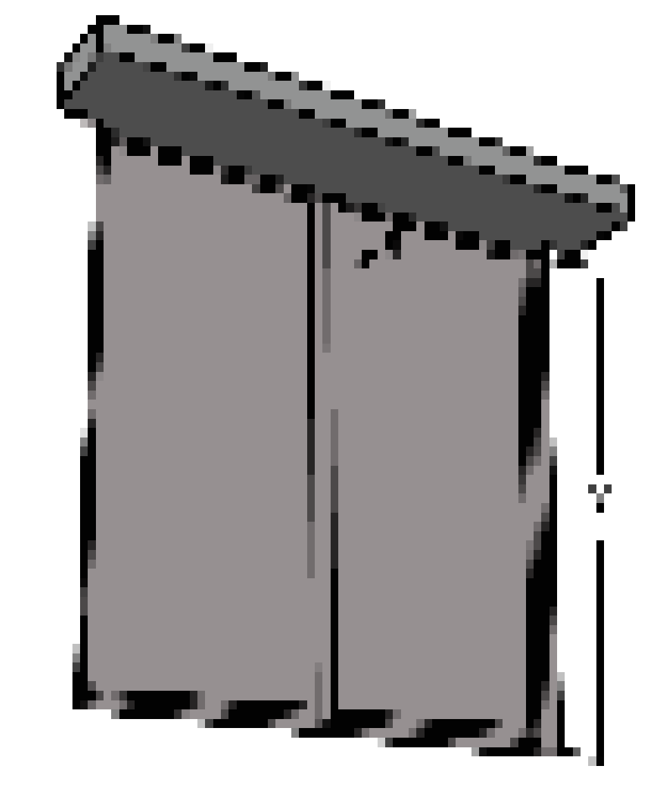
Figure 3.4.2 Horizontal shade: x ≥ 0.234y
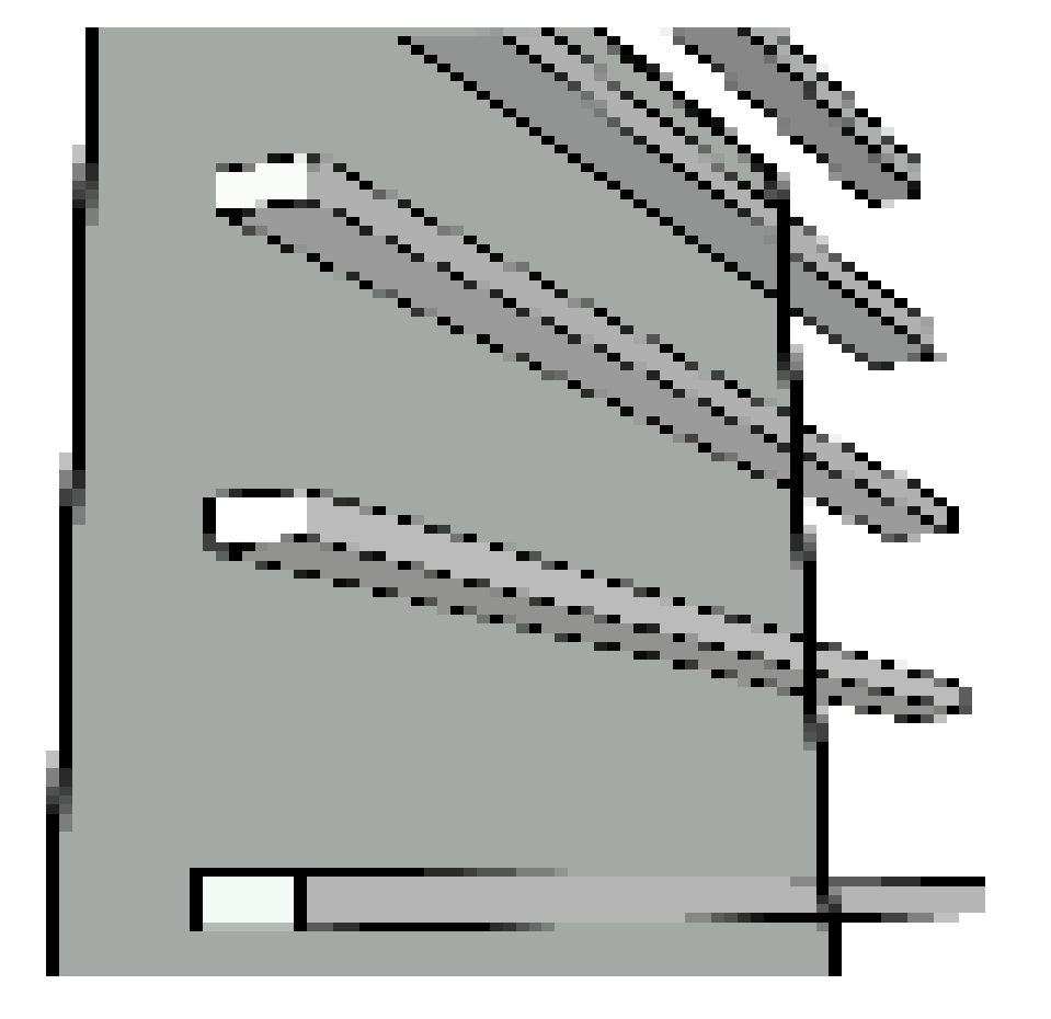
Figure 3.4.3 Horizontal Louvres: relationship between depth (x) and gap (y): x ≥ 0.234y
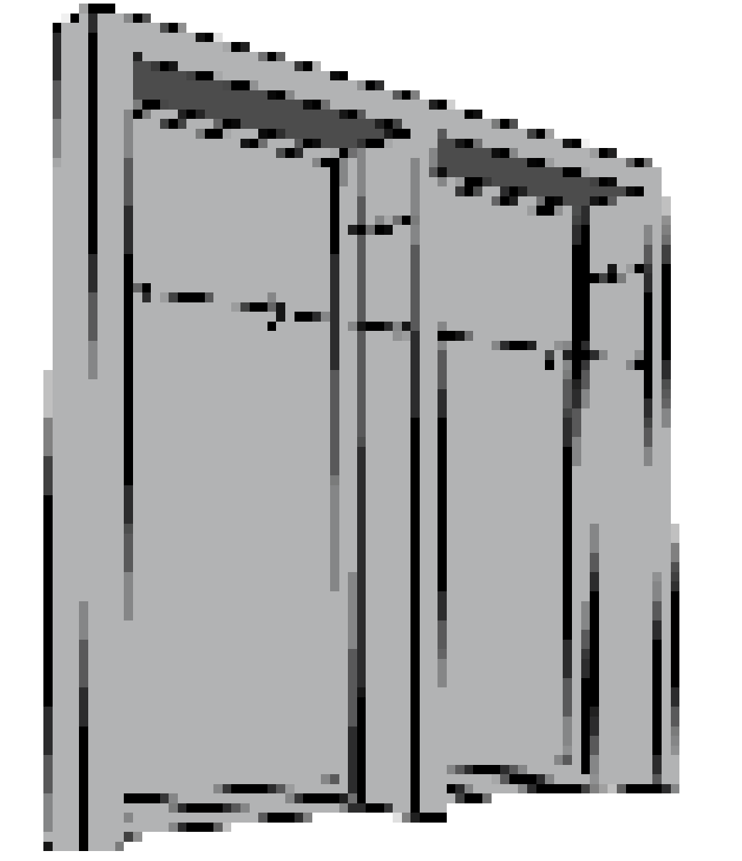
Figure 3.4.4 Vertical shading or louvres: relationship between depth (x) and gap (y): x ≥ 0.234y
4.4.4 Roof Insulation and Green Roofing System
4.4.4.1
Fifty (50) percent of horizontal exposed roof slabs of Buildings of Occupancy B, C, D and E, shall have green roofing system, to manage water run-off from roof tops, to control internal temperatures within the top floors and to reduce the carbon footprint of the building. This shall not include any covered roof surface, e.g. solar panels, solar thermal heaters, machinery for mechanical or electrical systems, water tanks, etc. Stair loft or machine room tops will be exempt from this rule.- (a) The roof slab design shall consider structural support of the green roof system, with growing medium of minimum 300 mm.
- (b) The design will indicate protection from dampness and provide a drainage system
4.4.4.2
Horizontal roof slabs, which are not covered by green roofing system, will have roof slabs with insulation, so that the time lag and decrement factor is greater than the other floor slabs of the building.4.5 Energy Efficient Building Systems
4.5.1 Daylighting and Supplementary Lighting System
4.5.1.1
Window area shall not be less than 14 percent or 1/7th of the total floor area of the building.4.5.1.2
Every regularly occupied space shall contain a minimum percentage of day-lit area along the building perimeter zones, with no window less than an area of 1 m2 and will ensure the appropriate stipulations given below.- (a) for rooms that measure less than 8 m in depth, window area shall be at least 20 percent of the area of the external wall of the room.
- (b) for rooms that measure between 8 to 14 m in depth, window area shall be at least 30 percent of the area of the external wall of the room and 35 percent of the external wall.
- (c) for rooms that measure more than 14 m in depth, window area shall be at least 35 percent of the area of the external wall of the room.
4.5.1.3
For Buildings of Occupancy A5, B, C, E1 and E2, photoelectric sensors shall be connected to luminaires, to enable dimming or switching off lamps that do not require to be operated, due to the presence of adequate daylight. The photoelectric sensor shall be located approximately at half (½) the depth of day-lit zone.4.5.1.4
If occupancy sensors are installed in the daylight area, the occupancy sensor shall override the daylight sensor during non-occupancy period. Exceptions:- (a) Zones with special requirements are exempt from the stipulation of Sec 4.5.1.3. The designer shall justify the reason for exemption.
- (b) Hotel guest rooms are exempt.
4.5.2 Lighting Power Density
4.5.2.1
Lighting Power Density (LPD) of the values set in Table 3.4.5 shall be provided for the respective functions within all building occupancies, or as specified.4.5.2.2
In addition to Sec 4.5.2.1, Illumination values (Lux) as specified in Tables 8.1.5 to 8.1.14 of Part 8 of this Code shall be provided for buildings of the respective occupancies.4.5.3 Occupancy Sensors
4.5.3.1
In order to limit the use of electricity in the unoccupied areas of buildings, occupancy sensors linked to lighting (except for emergency and security lighting) shall be installed in the public areas of buildings of occupancies specified in Table 3.4.6. Table 3.4.5: Maximum Allowable Lighting Power Density for Different Occupancies- LPD for car parks shall calculated from the total lighting power divided by the total car park area
4.5.3.2
For car parks a minimum 2/3rd of the lighting shall be controlled by occupancy sensors.4.5.3.3
Emergency lighting shall not be connected to occupancy sensors.4.5.4 Ceiling/ Wall Mounted Fans
4.5.4.1
For naturally ventilated buildings of occupancy A, ceiling/wall mounted fans shall be provided in each regularly occupied space.4.5.4.2
For buildings of occupancy B, C, D, E and I, ceiling/wall mounted fans shall be provided in each room larger than 25 m2 , with a minimum of one fan every 25 m2 . Exceptions:- (a) Corridors of buildings of all occupancies
- (b) ICU, CCU, operating theatres of Hospitals and Clinics
4.5.5 Lift and Escalator Efficiencies
4.5.5.1
Escalators, in buildings of all occupancies, shall be fitted with controls to reduce speed or to stop when no traffic is detected.4.5.5.2
Such escalators shall be designed with one of the energy saving features as described in i or ii below:- (i) Reduced speed control: The escalator shall change to a slower speed when no activity has been detected for a period of a maximum of three (3) minutes. Detection shall be by photocell activation at the top and bottom landing areas.
- (ii) Use on demand: The escalator shall shut down when no activity has been detected for a period of a maximum of fifteen (15) minutes, designed with energy efficient soft start technology. The escalator shall start automatically when required; activation shall be by photocells installed in the top and bottom landing areas.
4.5.5.3
Elevators (lift) in buildings of occupancy A5, D1, E1, E2, F1, F2, I1 and I3 occupancies shall be provided with controls to reduce the energy demand, using the following features in traction drive elevators:- (a) AC Variable-Voltage and Variable-Frequency (VVVF) drives on nonhydraulic elevators.
- (b) An average lamp efficacy, across all fittings in the lift car, of >55 lamp lumens/circuit watt, with provision for switching off, when lift is inactive for a period of a maximum of five (5) minutes.
- (c) The provision to operate in stand-by condition during off-peak periods, when the lift has been inactive for a period of a maximum of five (5) minutes.