
3.16.2
Amusement Building Exit Marking: Approved exit direction marking and exit signs shall be provided. Approved low-level exit signs and directional marking shall be located not more than 200 mm above parallel the walking surface and at the exit path.3.16.3
All exit signs shall be illuminated while in use at night, or during dark periods within the area served, in accordance with the provisions of this Code.3.16.4
The means of exit and exit access in buildings requiring more than one exit shall be equipped with artificial lighting. The lighting facilities shall satisfy the provisions of this Code.4.1 Scope
The provisions of this chapter shall control standards of the design, installation and maintenance of equipment and in-built fixed, localized, portable facilities required for firefighting within a building and its premises. The regulations of this chapter shall be applicable for all buildings and the provisions stated herein shall not cover the firefighting requirements outside the building premises.4.1.1
Extinguishing agents can be water, dry sand, ash, inert gas, dry chemical, and wet chemicals or mixed in nature of approved type. Agents will be selected as per the area have to extinguished.4.1.2
The gaseous system shall be only used where water or foam cannot be used for fire extinguishing because of the special nature of the contents within the building or areas to be protected.4.1.3
Fixed type fire protection system means there shall be a pipe circuit to cover full or part of a building and extinguishing agents supplied from a point. Localized fixed system means the system will cover a confined space with a self-extinguishing device fitted with a container ready to discharge automaticity. Portable type means the extinguishers can be hand carried in the site of incidents.4.1.4 Fire Classification
4.2 Fixed Type Fire Hydrant System
General area of application shall be Fire class A. Fixed type fire hydrant system comprises of, stand pipes and hose or reel pipes, sprinklers, drenchers or similar devices in appropriate combinations of these and capable of discharging water in an area which to be extinguish.4.2.1 Water Quantity for Fire Protection
The required flow rate and duration of water for sprinkler or stand pipe system use within the building according to their occupancy classification shall be in accordance with Table 4.4.1 and size of pipes shall be as per provisions of this Code or on the basis of the hydraulic design of the system to maintain flow rate and duration of water discharge.4.2.2 Water Sources for Fire Protection
Flow rate and duration of discharging water required for interior fire extinguishment of a building shall be supplied from one or any combination of the following sources. Table 4.4.1: Fire Protection Flow Requirements*- See also Sec 4.2.2.3.
- ** Values will be for one riser serving floor area of 1000 m2 .
- Light hazard-I : Occupancy groups, A1, A2, A3, E1 Light hazard-II : Occupancy groups, A4, A5, B, C, D,E2, E3, I2, I4, F1 Ordinary hazard-I : Occupancy groups, I1, I3, I5, F2, F3, G1 Ordinary hazard- II : Occupancy groups, G2 , H1 Ordinary hazard- III : Occupancy groups, H2 Extra hazard : Occupancy group J-pressure and flow requirement for this group shall be determined by Fire Department but shall not be less than required value for Ordinary hazard- III
4.2.2.1 Direct connection to water main
For continuous water supply (public water supply system or private system) with sufficient quantity and pressure to feed and discharge firefighting equipment during peak demand period, direct connection of firefighting system to the water main may be adopted, Figure 4.4.1. In this case guidelines specified in NFPA 22 are to be followed.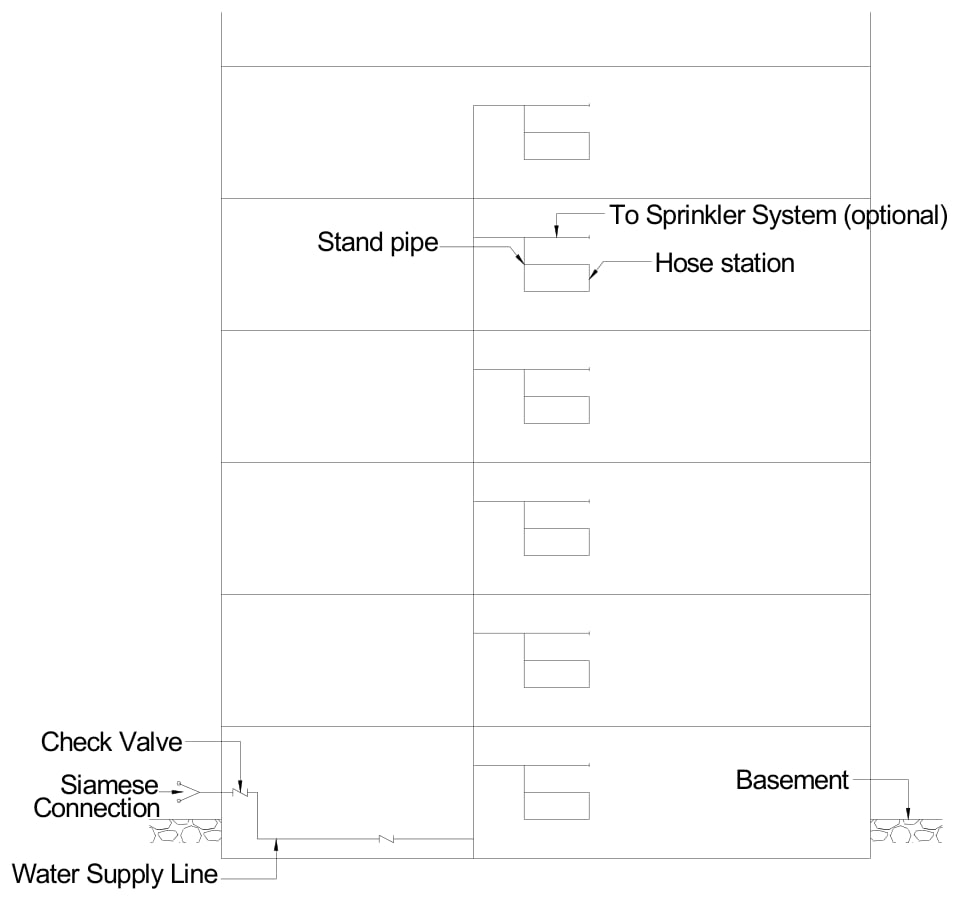
Figure 4.4.1 Typical diagram for standpipe and hose system connected directly to the water main
4.2.2.2 Roof gravity tanks
Any elevated structure holding a water reservoir or water tank or in any level within a building and having downward supply pipelines shall be termed as gravity tank only when a water reservoir located on a roof of a building shall be termed as roof gravity tank. For water supply system with inadequate quantity or pressure during peak demand period but with sufficient pressure to feed roof tank, a roof gravity tank may be provided. In that case any one of the following steps shall be followed.- (a) If only the static height of the roof gravity tank is used to feed and discharge the firefighting equipment, the height of the roof gravity tank from the top floor must be sufficient to create minimum required pressure at the top floor hydrant point. The minimum pressure at hose outlet for standpipes supplying a 50 mm or larger hose shall be at least 300 kPa. This minimum pressure for standpipe system supplying first aid hose (38 mm nominal) shall be at least 200 kPa. This minimum pressure for combination of sprinkler and hose pipe system shall be 600 kPa. To maintain the above required pressure the vertical distance of the roof gravity tank from the top floor hydrant point shall be at 31 m, 20.5 m and 62 m respectively, Figure 4.4.2.
- (b) If the vertical distance between the roof gravity tank and the top floor hydrant point cannot be maintained for gaining required pressure and discharge, fire pump of required size and number shall be installed with standard manufacturer recommended suction and delivery connections, Figures 4.4.3 and 4.4.4.

Figure 4.4.2 Typical diagram showing required static head of gravity roof tank with adequate domestic and fire reserve
4.2.2.3 Storage tank
In absence of public water supply system, the building premises shall have individual water sources specified in Part 8. For water supply system, to feed and discharge by firefighting equipment, the building premises may have deep tube well with required flow, water wells, natural water sources or a ground (or underground) tank, roof top tank, swimming pools etc. The capacity of these facilities shall be sufficient to satisfy the flow requirement as specify in Table 4.4.1.4.2.2.4 Water supply test
After installation of the hydrant system, a flow test shall be conducted to verify the capacity of the discharge system such that the installation can fulfill the minimum capacity (flow and time) as specified in Table 4.4.1. This system shall be periodically inspected, maintained and tested in accordance with NFPA 25.4.2.2.5 Fire pump
The firefighting equipment shall be directly feed by automatic main fire pump. Centrifugal pump, turbine-type pump (submerged or with vertical shaft) or positive displacement pumps with adequate supply pressure and flow capacity shall be used for water supply during demand. Centrifugal pumps shall not be used where a static suction lift is required. Once the pump starts, it shall run continuously until stopped manually. The pump shall be fully operational within 30 seconds after starting. There shall be provision for manual starting where priming is necessary. Automatic priming equipment is necessary to ensure priming at all times. The fire pump shall not be used for other purpose. Fire pumps shall have the rated capacities as shown in Table 4.4.2. The pump shall be rated at net pressure of 272 kPa or more as per requirement of the firefighting system demand. For pump installation procedure and fittings NFPA 20 shall be followed. The pump shall be housed in a readily accessible position in a building of noncombustible construction. The pump shall be adequately protected against mechanical damage. There shall be a provision for secondary fire pump which can be operated by a dedicated diesel engine or by an alternate power supply source with adequate control system and incompliance with safety operation during fire. Quality of the pump assembly shall comply with the specification of International Association of Fire.
Figure 4.4.3 Typical diagram for gravity roof tank with adequate domestic and fire reserve (The fire pump is on the roof)
4.2.3 Design Considerations for Standpipe and Hose System
4.2.3.1
The fire protection system shall be designed for their effective use either by amateur or trained firefighting personnel or both.4.2.3.2
All standpipes in standpipe system shall be sized so that they will provide a minimum flow specified in Table 4.4.1. In standpipe system with more than one standpipe, the supply piping shall be sized for the minimum flow specified in Table 4.4.1 for the first standpipe plus 1000 litre per minute for each additional standpipe. The total number of such additional standpipes shall not be more than 8. All standpipe risers shall be interconnected through check valves of equivalent size to prevent recirculation.
Figure 4.4.4 Typical diagram for gravity roof tank with adequate domestic and fire reserve (The fire pump at the ground level)
4.2.3.3
The minimum pressure for standpipes supplying a 50 mm or larger diameter hose shall be at least 300 kPa. For standpipe supplying first aid hose (38 mm nominal diameter) may have a minimum pressure of 200 kPa. The maximum pressure at any point of the system shall not exceed 2434 kPa, if the hose connection at 40 mm diameter outlet exceeds 700 kPa approved pressure regulating device shall be installed to maintain the above maximum limits.4.2.3.4
Diameter of the standpipe termed as size shall comply with flow and capacity requirement of the pump shown in Table 4.4.2 or hydraulically design to provide required flow and pressure at the topmost hydrant point. Table 4.4.2: Fire Pump Data4.2.3.5
The water supply required for combined system (for partial automatic sprinkler and Fire Department hose) shall be calculated in accordance with Table 4.4.1 plus an amount equal to the hydraulically calculated sprinkler demand.4.2.3.6
The system for firefighting purpose may be designed with automatic fire pump with water tank at the ground as shown in Figure 4.4.5.4.2.3.7
The water stored in storage tank for firefighting operation shall not be used for other purposes. Accordingly, separate water connections should be provided as shown in Figure 4.4.6.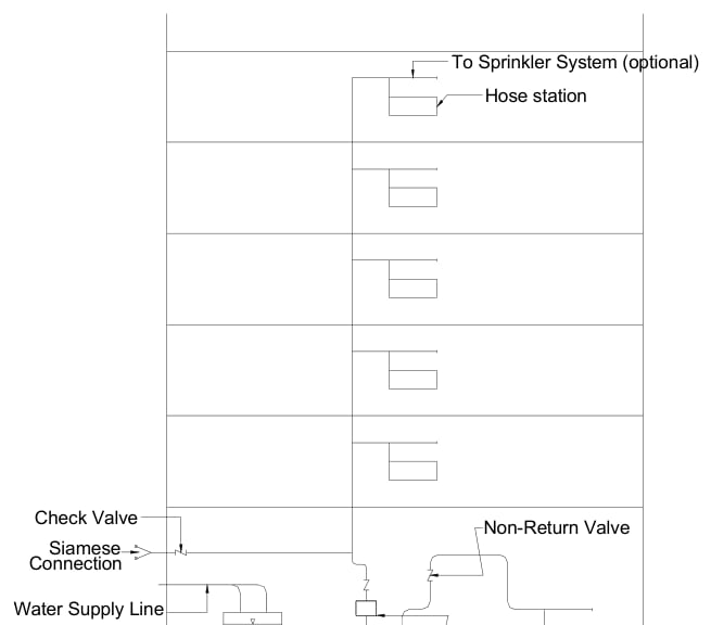
Figure 4.4.5 Typical diagram for fire protection with ground tank and automatic fire pump

Figure 4.4.6 Typical diagram for storage tank (ground or overhead) with domestic and fire reserve
4.2.3.8
The ground storage tank shall be easily accessible to fire engine of Fire Department. In absence of space available for fire engine, the cover slab of ground storage tank shall be designed to withstand a vehicular load of local fire engine.4.2.3.9
The standpipe shall be located such as intermediate stair landing, vestibules or nearby in noncombustible enclosure such that it will be able to provide hose stream to the most remote area of the floor served.4.2.3.10
The hose shall be connected to the standpipe within a height not more than 1.5 m from the finished floor level. The hose stations shall be easily accessible for inspection and testing.4.2.3.11
The hose connection to a standpipe for large stream shall be at least 100 mm nominal and that of small stream may be 63 mm or 50 mm on each point. The size of first aid hose shall be 38 mm nominal. The hose length shall not be more than 30 m.4.2.3.12
Different piping materials and fittings for standpipe system presented in Tables 4.4.3 and 4.4.4 shall conform to the standard or one of the standards cited against them. The standard requirements for other materials not provided in these tables shall be subject to the approval of the Authority. Table 4.4.3: Piping for Standpipe System4.2.3.13
The standpipe riser shall be supported at the top and at the lowest level. The riser shall also be provided with support at the alternate level in between top and bottom level of the standpipe riser. The support shall be of adequate strength to support the water-filled pipe load and an additional load of 110 kg.4.2.3.14
The horizontal standpipe shall have hangers with a spacing not more than 5 m. The hanger shall be able to carry a load of five times the weight of the water-filled pipe and an additional load of 110 kg.4.2.3.15
There shall be Siamese connection also termed as firemen connection to the standpipe or to the delivery pipe of the gravity roof storage tank. The location of Siamese connection shall be easily accessible from the street or means of access.4.2.3.16
The system shall be provided with adequate drainage piping to discharge under pressure. The drain pipe shall not discharge into sanitary sewer.4.2.3.17
All control valves shall be designed to withstand the pressure specified in Sec 4.2.3.34.2.4 Wet Riser
A wet riser is a vertical pipe of not less than 100 mm internal diameter, kept permanently charged with water which is then immediately available for use on any floor in the building at which a hydrant or landing valve is provided. The riser is connected to a booster pump or town main of suitable capacity so that they are capable to supply four 13 mm jet at 2.5 bars at the highest outlets.4.2.5 Down Comer
A similar function to that of wet riser is performed by down comer which like a wet riser is constructed of vertical piping, with outlets at different levels, but is supplied with water from a tank in the roof through terrace pump, gate valve and non-return valve. It is also fitted with inlet connections at ground level and air release valve at roof level for being capable of charged with water by pumping from fire engines.4.2.6 High Velocity Water Spraying Projector System
This system applies water in the form of conical spray consisting of droplets of water traveling at high velocity. The three principles of extinguishments are employed, namely emulsification, cooling and dilution. While the water droplets are passing through the flame zone, some of the water is turned into steam, diluting the oxygen feeding the fire. Addition of water to the burning oil also cools it and reduces the rate of vaporization. In addition to this droplets of water traveling at high velocity bombard the surface of the oil to form an emulsion of oil and water that will not support combustion.4.2.7 Water Mist Technology
Fine water spray suppression system can extinguish fires using water and nitrogen from air. Nozzle is used to atomize water by nitrogen or other suitable media to generate mist or fog of finely controlled water droplets. The system operates at low pressure and produces droplets in a range of 80 to 200 microns. These droplets extinguish fire rapidly and efficiently even those involving highly volatile hydrocarbons. This system is an alternative to Halon and other gaseous system in many applications.4.2.8 Drenchers
Drenchers are used for the external protection of the building against exposure hazard, or radiant heat. Drencher heads are similar to sprinkler heads and may be sealed or unsealed. Drenchers are of three types, roof drenchers, wall drenchers, window drenchers.4.2.9 Dry Riser System
Dry riser stand pipe system shall be an equivalent alternative of wet riser stand pipe system. The water supply for an automatic or semi-automatic standpipe system shall be designed such that the system must be capable of supply the system during peak demand hour.4.2.10 Design Consideration of Sprinkler System
4.2.10.1
A system of water pipes fitted with sprinkler heads as per manufacturers specification may be installed actuate automatically, control and extinguish a fire by the discharge of water.4.2.10.2
The pipe schedule sizing to supply different number of sprinklers for their different uses may be in accordance with Tables 4.4.5 and 4.4.64.2.10.3
Each sprinkler shall serve a maximum ceiling area specified in Table 4.4.7 for different types of building according to their uses.4.2.10.4
Water supply piping and fittings for sprinkler system shall conform to the standard or one of the standards cited against them in accordance with Tables 4.4.4 and 4.4.8. The standard requirements for other pipe materials not provided in these tables shall be subject to the approval of the Authority.4.2.10.5
The sprinkler system shall be provided with adequate support or made flexible to prevent pipe breakage during earthquake.4.2.10.6
The hanger in sprinkler system shall be designed to carry a load equal to five times the weight of the water-filled pipe plus an addition load of 110 kg. The support shall be designed to support a load equal to the weight-filled pipe plus and additional load of 110 kg.4.2.11 Connection
4.2.11.1
There shall be Siamese connection to the sprinkler system located outside the building and accessible to the fire department connection.4.2.11.2
All risers shall be connected through a gate valve with a main of size equal to that largest riser.4.2.11.3
The sprinkler system shall be provided with adequate drainage arrangement. The drain pipe shall not discharge into sanitary sewer.4.2.11.4
All control valves and fittings shall be able to withstand the pressure specified in Sec 4.2.3.3.4.2.12 Inspection, Testing and Maintenance
4.2.12.1 Inspection
All piping and equipment shall be inspected for satisfactory supports in accordance with Sec 6.15 in Part 8 of this Code and protection from damage and corrosion. All outlets shall be free from obstruction. Table 4.4.5: Size of Water Supply Steel Pipe to Sprinklers- Definitions of these terms are given in Table 4.4.1.
- Definition of these terms is given in Table 4.4.1.
- ** No limit.
- *** One sprinkler system riser or combined system riser shall serve the floor area not more than 4850 m2 for light and ordinary hazard occupancy and 2325 m2 for extra hazard occupancy
- Maximum distance in m between sprinklers and between line of piping.
-
- The definitions of these terms are given in Table 4.4.1.
- ** * Storage facilities which permit closely piled materials over 4.5 m or materials on rack over 3.6 m.
4.2.12.2 Testing
Fire protection plumbing system or part thereof shall be tested and approved after installation by the Authority.- (a) Testing of Standpipe System: The hydrant pipes shall be hydraulically tested to a pressure 1400 kPa or 150% of working pressure whichever is the higher for 2 hours without any leakage at any points. The system shall be able to maintain
- (b) Testing of Sprinkler System: This system shall be tested for at least 2 hours for a pressure of 1000 kPa or at 350 kPa in excess of normal working pressure when normal working pressure will be more than 650 kPa. The system shall be able to maintain above test pressures. The system shall also be tested for the required flow at the highest outlet.
- (c) Testing of Sprinkler System Pump: The pump used for sprinkler system firefighting purpose shall be tested by approved authority for their performance characteristics and this test report must be submitted at the time of supply of pump. The pump shall be retested or repaired to its original condition if their performance characteristics fall below more than 10 percent of the supplier’s test characteristic curve or as specified for the fire protection water supply system.
4.2.12.3 Maintenance
The system shall be maintained for safe operating conditions and tested at least once a year.4.3 Fixed Installation Other Than Water
Other than water there are different types of fixed installation. These are of mainly two types. (a) Centrally fixed, (b) locally fixed.4.3.1 Centrally Fixed Installation Discharging Extinguishing Agent other than Water
4.3.1.1 General
This installation can be of two types, one for zone coverage and the other for total coverage. For these system pipe circuits and exhaust manifold are required and shall have special discharging Alarm distinctly different than fire alarm. These fixed installations can be of different types, such as (a) Foam installation, (b) Vaporizing liquid installation, (c) Dry powder installation. (d) Gaseous installation (e) Dry chemical installation (f) Wet chemical installation.4.3.1.2 Foam installation
Foam extinguishing system shall be of an approved type and shall be installed in accordance with the specification of the manufacturer. The foam extinguishing system is designed to discharge fire suppressive foam concentrates over the area to be protected.- (a) There are different types of foam installation, such as (i) Pump operated mechanical foam installation, (ii) Self-contained pressurized installation, (iii) Pre-Mixed Foam installation, (iv) High Expansion Foam installation.
- (b) A foam extinguishing system shall be automatically actuated during a fire with provision of manual actuation.
- (c) Warning sign and discharge alarm system shall be provided with the foam extinguishing system, which shall be actuated during the use of the system.
- (d) The system provides protection of boiler rooms with its ancillary storage of furnace oils in basement and other areas where hazardous liquids are stored.
4.3.1.3 Vaporizing liquid installation
Liquefied compressed Halogenated hydrocarbon is fed through distribution pipe works and specially designed discharged nozzles to the area need to be extinguished. Upon discharge the liquid immediately vaporized to form a heavy vapour which achieves very rapid extinction. There are two types of Vaporizing liquid installation, such as total flooding system and Local application system. This system shall be installed in accordance with the specification of the manufacturer. Safe guards are necessary to prevent injury or death of personnel in area where the atmosphere may be made hazardous by the discharge.4.3.1.4 Dry powder installation
Dry powder of certain chemicals installation consist of pipe work and discharge nozzle and pressuring media. This installation can be operated automatically or manually. This can be designed for total coverage and for zone coverage. Dry powder is a range of chemical agents available as extinguishing media. They are used on various flammable liquids where they are confined. This system shall be installed in accordance with the specification of the manufacturer.4.3.1.5 Gaseous installation
- (a) General: Gaseous extinguishing system shall be of an approved type and shall be installed as per provisions of this Code. The system supplies gas from a pressurized vessel through fixed pipes and nozzles.
- (b) The system is used where water or foam cannot be used for fire extinguishing because of the special nature of the contents within the building or areas to be protected.
- (c) The system shall be automatically actuated and shall be equipped with manual actuation devices as well.
- (d) Warning signs and discharge alarm shall be provided where persons are likely to be trapped in an area made hazardous due to discharge of extinguishing gases.
- (e) Halocarbon agents and inert gas system: Any approved Type of Halocarbon agents are chemicals in the liquid form at high pressure and vaporize readily leaving no residue. These are primarily to protect hazardous fire in enclosed room, vaults, machines, containers, storage tanks, engines, unattended computer server rooms, electrical appliances, liquid gas storage etc. Some example of these chemical is dichlorodifluoro ethane, chlorodifluoro methane. Inert gas system is also an alternative of Halocarbon agents. These are nitrogen and argon in pure form or in mixer at different proportion. These gases are identified as clean total folding fire suppression agents. They are stored in high pressure gas cylinders.
4.3.1.6 Dry chemical extinguishing system
- (a) General: Dry chemical extinguishing system shall be of an approved type and shall be installed in accordance with the provisions of this Code and manufacture’s instruction.
- (b) The system shall be automatically actuated during a fire and shall be equipped with manual actuation device as well.
- (c) Warning signs and discharge alarm shall be provided where persons are likely to be exposed to chemical discharge. Chemical agents of the system shall be nontoxic.
4.3.1.7 Wet chemical extinguishing system
- (a) A wet chemical system is a solution of water and potassium carbonate or acetate based chemical which forms the extinguishing agent. The system shall be installed in accordance with the provisions of this Code and manufacturer’s installation instruction.
- (b) The system shall be automatically actuated during a fire and shall be equipped with manual actuation device as well.
- (c) In case of wet chemical extinguishing system, label of the approved agent shall be affixed.
- (d) Warning signs and discharge alarm shall be provided where persons are likely to be exposed to wet chemical discharge.
4.3.2 Localized Fixed
Containerized extinguishing agent are available in different shapes and size to be placed in different locations those are prone to fire hazard as for example at the top of cookers in the kitchen, electric connection box etc. Use of these containers shall be approved type and installation shall be as per specification of the manufacturer.4.4 Portable Fire Extinguisher
4.4.1
Portable fire extinguishers shall readily available in different type. These are portable fire extinguisher are of carbon dioxide types, dry chemical types, water types, and Halon types, film-forming type, foam types and Halon carbon type. For proper operation persons with adequate knowledge and familiar with their operation must be available.4.4.2
In accordance with the occupancy hazard, specification of the manufacturer and guide line set by NFPA 10, the minimum number of portable fire extinguishers for different class of fire shall be ascertained. As for example where the floor area of a building is less than 279 m2 at least one fire extinguisher of the minimum size is recommended for Fire Class A.4.4.3
Portable fire extinguishers shall be fully charged, operable at any time and conspicuously located where they will be readily accessible. Portable fire extinguishers shall not be obstructed or obscured from view. In large rooms, means shall be provided to indicate the extinguisher location.4.4.4
Portable fire extinguishers shall be adequately protected from impact, vibration, and adverse environment and shall not be exposed to temperatures outside the listed temperature range shown on the fire extinguisher label.4.4.5
Portable fire extinguishers mounted in cabinets or wall recesses shall be placed so that the fire extinguisher operating instructions face outward. The location of such fire extinguishers shall be marked conspicuously.4.4.6
The owner or designated agent or occupant of a property in which fire portable extinguishers are located shall be responsible for inspection, maintenance, and recharging. The procedure for inspection and maintenance of fire extinguishers varies considerably. Monthly “quick check” or inspection in order to follow the inspection procedure as outlined in NFPA 10 shall be done.4.4.7
Maintenance, servicing and recharging shall be performed by trained persons having available the appropriate servicing manual(s), the proper types of tools, recharge materials, lubricants, and manufacturer’s recommended replacement parts or parts specifically listed for use in the fire extinguisher. These extinguishers shall be maintained as per NFPA 10, at intervals of not more than one (1) year.4.4.8
All rechargeable-type fire extinguishers shall be recharged after any use or as indicated by an inspection or when performing maintenance or as per the recommendations of the manufacturer.4.4.9
For personal safety during approach with extinguishing equipment it shall be remembered that most fires produce toxic decomposition products of combustion and some materials can produce highly toxic gases. Fires can also consume available oxygen or produce dangerously high heat. All of these can affect the degree to which a fire can be safely extinguished.4.4.10
All extinguishing agents other than clean agents shall be approved by the authorities having jurisdiction.4.5 Rate of Water Flow For Fire Protection In Tall Building
High rise building exceeding 80 meter height shall be termed as Tall Building. The quantity, sources and mode of water supply in tall building shall be in accordance with Sec 4.2. In high rise buildings fittings and equipment for firefighting may be subject to excessive pressure. Pressure on firefighting equipment in Tall building shall be reduced by dividing the building into different zones. In this process the building shall be divided into different water supply zones so that the firefighting equipment will serve within their maximum allowable limit of pressure. Separate automatic fire pump or combination of tank and automatic pump shall be installed for supplying water to the firefighting equipment in each zone as per Figures 4.4.7 and 4.4.8.4.6 Fire Detection and Alarm System
4.6.1 Fire Detection Shall be Done by the Following Ways
(a) Human surveillance: Human surveillance shall be acceptable where the user and occupant are capable of maintaining surveillance for detecting fire and smoke when a person appointed and assigned to detect fire shall be termed as Fire watch. (b) Automatic smoke or/and heat detection : The installation of automatic fire and smoke detection system shall be a necessity when the size, arrangement and occupancy of a building become such that a fire itself cannot provide adequate warning to its occupants. The automatic fire and smoke detection system shall include, spot or line type heat sensitive detectors and optical, ionized or chemical sensitive type of smoke detectors. (c) Video surveillance : Cameras capable of registering and transmitting real time images in to a monitoring device having display commonly termed as CCTV shall be installed systematically to cover an area for detecting any incision of smoke and fire. This CCTV will remain under either human surveillance or monitored by compatible software to transmit signal automatically to the fire alarm system and also to the authorized persons.4.6.2 Fire Alarm System
4.6.2.1
In a fire incident, panic management shall be the prime concern for a successful relocation, delayed egress or evacuation of occupants from a building structure. Activation of alarm shall be sequential and compatible with all design scenarios. Means of egress system is so designed that all alarms of a building shall not be activated at a time. A general announcement of fire shall be done for the occupant or the word “Fire” shall be avoided but authorized persons responsible for evacuation shall be alerted through Password or Pass Phrase. As per design scenarios a systemic execution protocol shall be developed where a building shall be sub-divided into zones for installation alarms and for fight in place, relocation of occupants, delayed egress or immediate evacuation. Alarm system can be of different types, such as audible alarm, visual alarm, vibration alarm, and display alarm.- (a) Audible alarm: Ringer, bell, horn, chime and voice command via public address system (PA system) are the examples of audible alarm system.
- (b) Visual Alarm: A bright white light emitting device with specific intensity and cycle of emission is capable to draw attention of a person having limited hearing shall be termed as visual alarm. A visual alarm shall be installed where a person working alone in a room or a space having hearing limitations. In a public place or in any place more than two persons are present and one having normal hearing ability shall not require to install visual alarm.
- (c) Vibration Alarm: Alarm activated through vibration can be used for alarm.
- (d) Display Alarm: Textual, graphical or pictorial display on screens or monitors can be used as alarm.
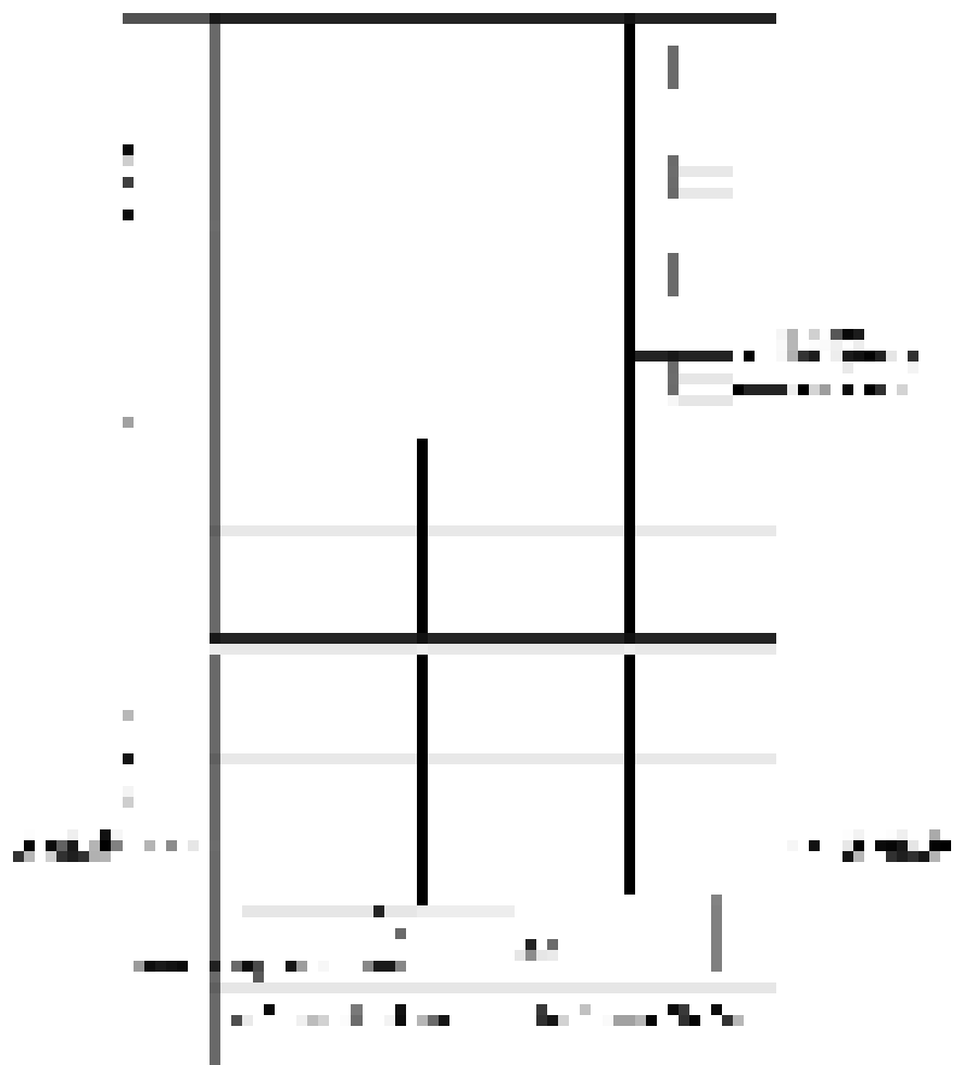
Figure 4.4.7 Typical diagram for fire protection in different water supply zones of a tall building
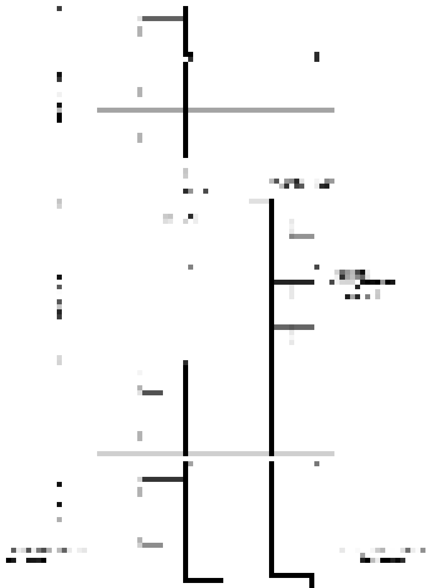
Figure 4.4.8 Typical diagram for fire protection in different water supply zones of a tall building