
3.1 General
The Soils and Foundations Chapter of the Code is divided into the following three distinct Divisions: Division A: Site Investigations, Soil Classifications, Materials and Foundation Types- Division B: Service Load Design Method of Foundations
- Division C: Additional Considerations in Planning, Design and Construction of Building Foundations
- Site Investigations
- Identification, Classification and Description of Soils
- Materials
- Types of Foundation
- Shallow Foundations
- Geotechnical Design of Shallow Foundations
- Geotechnical Design of Deep Foundations
- Field Tests for Driven Piles and Drilled Shafts
- Excavation
- Dewatering
- Slope Stability of Adjoining Building
- Fills
- Retaining Walls for Foundations
- Waterproofing and Damp-proofing
- Foundation on Slopes
- Foundations on Fill and Problematic Soils
- Foundation Design for Dynamic Forces
- Geo-hazards for Buildings
3.2 Scope
The provisions of this Chapter shall be applicable to the design and construction of foundations of buildings and structures for the safe support of dead and superimposed loads without exceeding the allowable bearing stresses, permissible settlements and design capability. Because of uncertainties and randomness involved in sub-soil characteristics, Geotechnical Engineering requires a high degree of engineering judgment. As such the Code provisions of this Chapter provided here under, are kept elaborative for better understanding of the readers. Provisions that are stated in imperative form using “shall” are mandatory. Other provisions of this Chapter should be followed using sound Geotechnical Engineering judgment.3.3 Definitions and Symbols
3.3.1 Definitions
For the terms used in this Chapter, the following definitions shall apply. ALLOWABLE It is the minimum of the safe bearing capacity and BEARING CAPACITY safe settlement pressure, so that the foundation/ structure is safe and stable under both shear failure and settlement criteria. It may be denoted by symbol . The lateral dimensions of the foundation (width or diameter and the length) are designed on the basis of allowable bearing capacity. Also known as Allowable Bearing Pressure. ALLOWABLE LOAD The maximum load that may be safely applied to a foundation unit, considering both the strength and settlement of the soil, under expected loading and soil conditions. ANGULAR Angle between the horizontal and any two DISTORTION foundations or two points in a single foundation. AUGUR PILE Same as SCREW PILE. BATTER PILE The pile which is installed at an angle to the vertical in order to carry lateral loads along with the vertical loads. This is also known as RAKER PILE. BEARING CAPACITY The general term used to describe the load carrying capacity of foundation soil or rock in terms of average pressure that enables it to bear and transmit loads from a structure.3.3.2 Symbols and Notation
Every symbol used in this Chapter is explained where it first appears in the text. However, for convenience of the reader, a list of main symbols and notation is provided as under. Other common symbols and notation like those of soil classifications are not included in this list.- = Cross sectional area of pile
- = End bearing area of pile
- = Skin friction area (perimeter area) of pile
- = Width of footing/foundation (Sec 3.9.6, Sec 3.20.2)
- = Smallest dimension of pile group (Sec 3.10.5)
- = Width of plate
- = Reference width (300 mm) for computation of pile settlement
- = Cation exchange capacity
- = Cyclic resistance ratio
- = Cyclic stress ratio
- = Compression index of soil
- = Empirical coefficient used for pile settlement computation
- = Uniformity coefficient
- = Coefficient of curvature
- = Diameter or width of pile
- = Diameter of pile at base
- = Critical depth of soil layer
- = Effective grain size; the size of soil particle from which 10 percent of the soil is finer
- = The size of soil particle from which 30 percent of the soil is finer
- = The size of soil particle from which 60 percent of the soil is finer
- = Flexural rigidity of footing
- = Exchangeable magnesium percentage
- = Modulus of elasticity of pile material
- = Modulus of elasticity of soil
- = Exchangeable sodium percentage
- = Factor of safety against liquefaction
- = Factor of safety
- = Modulus of rigidity
- = Height of wall from foundation footing (Sec 3.9.4)
- = Layer thickness (Sec 3.10.5)
- = Thickness of sample (Sec 3.5.6)
- = Final thickness of sample (Sec 3.5.6)
- = Plasticity index
- = Relative subsidence
- = Coefficient of earth pressure
- = Coefficient of earth pressure at rest
- = Length of pile (Sec 3.10)
- = Length of deflected part of wall/raft or centre to centre distance between columns. (Sec 3.9.4)
- = Liquid limit
- = Standard penetration test value (SPT)
- = Corrected SPT value for field procedures
- = Average SPT value
- = Corrected SPT value for overburden pressure (for sandy soil)
- = Bearing capacity factors
- = Overconsolidation ratio
- = Plasticity index; same as
- = Allowable load
- = End bearing at the base or tip of the pile
- = Load transferred to the soil at pile tip level
- = Skin friction or shaft friction or side shear
- = Ultimate bearing/load carrying capacity
- = Group settlement ratio of pile group
- = Settlement due to axial deformation
- = Settlement of pile group
- = Settlement at pile tip
- = Settlement of pile due to skin friction
- = Degree of saturation
- = Total settlement of a single pile
- = Weight of the pile
- = Weighted plasticity index
- = Peak horizontal acceleration on the ground surface
- = Apparent cohesion of soil
- = Undrained cohesion of soil
- = Diameter of pile
- = Void ratio
- = Critical void ratio
- = Void ratio at liquid limit
- = Void ratio at plastic limit
- = Initial void ratio
- = Initial void ratio; same as
- = End bearing resistance on unit tip area of pile
- = Natural frequency
- = Skin frictional resistance on unit surface area of pile
- = Adhesive stress (Sec. 3.10.1.12)
- = Gravitational acceleration
- = Modulus of sub-grade reaction
- = Stiffness of soil
- = Coefficient of horizontal soil stress
- = Total mass of machine foundation system
- = Mass of foundation block
- = Mass of soil
- = Number of pile in a group
- = Allowable bearing capacity of shallow foundation
- = Ultimate end bearing capacity pile
- = Net safe ultimate bearing capacity of shallow foundation
- = Net ultimate bearing capacity of shallow foundation
- = Safe ultimate bearing capacity
- = Safe settlement pressure of shallow foundation
- = Unconfined compressive strength
- = Ultimate bearing capacity of shallow foundation
- = Stress reduction coefficient to allow for the deformability of the soil column
- = undrained shear strength; same as
- = Liquid limit; same as LL
- = Depth
- = Thickness of any () layer
- = Adhesion factor
- = Ratio of footing length to width (Sec 3.9.6.8)
- = Friction factor due to overburden (3.10.1)
- = Unit weight of the soil
- = Unit weight of water
- = Total settlement
- = Consolidation settlement
- = Elastic settlement
- = Immediate settlement
- = Secondary consolidation settlement
- = Poisson’s ratio of soil
- = Initial effective stress at mid-point of a soil layer
- = Increase in effective stress at mid-point of a soil layer due to increase in stress
- = Reference stress (100 kPa) for computation of pile settlement
- = The total vertical stress
- = Effective vertical stress
- = Effective vertical stress; same as
- = Maximum shear stress
- = Apparent angle of internal friction
- = Effective/drained angle of internal friction
- = Soil shaft interface friction angle
- = natural circular frequency Division A: Site Investigations, Soil Classifications, Materials and Foundation Types (Sections 3.4 to 3.7)
3.4 Site Investigations
3.4.1 Sub-Surface Survey
Depending on the type of project thorough investigations has to be carried out for identification, location, alignment and depth of various utilities, e.g., pipelines, cables, sewerage lines, water mains etc. below the surface of existing ground level. Detailed survey may also be conducted to ascertain the topography of existing ground.3.4.2 Sub-Soil Investigations
Sub soil investigation shall be done describing the character, nature, load bearing capacity and settlement capacity of the soil before constructing a new building and structure or for alteration of the foundation of an existing structure. The aims of a geotechnical investigation are to establish the soil, rock and groundwater conditions, to determine the properties of the soil and rock, and to gather additional relevant knowledge about the site. Careful collection, recording and interpretation of geotechnical information shall be made. This information shall include ground conditions, geology, geomorphology, seismicity and hydrology, as relevant. Indications of the variability of the ground shall be taken into account. An engineering geological study may be an important consideration to establish the physiographic setting and stratigraphic sequences of soil strata of the area. Geological and agricultural soil maps of the area may give valuable information of site conditions. During the various phases of sub-soil investigations, e.g. drilling of boreholes, field tests, sampling, groundwater measurements, etc. a competent graduate engineer having experiences in supervising sub-soil exploration works shall be employed by the drilling contractor.3.4.3 Methods of Exploration
Sub soil exploration process may be grouped into three types of activities such as: reconnaissance, exploration and detailed investigations. The reconnaissance method includes geophysical measurements, sounding or probing, while exploratory methods involve various drilling techniques. Field investigations should comprise :- (i) Drilling and/or excavations (test pits including exploratory boreholes) for sampling;
- (ii)Groundwater measurements;
- (iii)Field tests.
- (i) Field testing (e.g. CPT, SPT, dynamic probing, WST, pressuremeter tests, dilatometer tests, plate load tests, field vane tests and permeability tests);
- (ii)Soil sampling for description of the soil and laboratory tests;
- (iii)Groundwater measurements to determine the groundwater table or the pore pressure profile and their fluctuations
- (iv) Geophysical investigations (e.g. seismic profiling, ground penetrating radar, resistivity measurements and down hole logging);
- (v) Large scale tests, for example to determine the bearing capacity or the behaviour directly on prototype elements, such as anchors.
3.4.4 Number and Location of Investigation Points
The locations of investigation points, e.g., pits and boreholes shall be selected on the basis of the preliminary investigations as a function of the geological conditions, the dimensions of the structure and the engineering problems involved. When selecting the locations of investigation points, the following should be observed:- (i) The investigation points should be arranged in such a pattern that the stratification can be assessed across the site;
- (ii) The investigation points for a building or structure should be placed at critical points relative to the shape, structural behaviour and expected load distribution (e.g. at the corners of the foundation area);
- (iii) For linear structures, investigation points should be arranged at adequate offsets to the centre line, depending on the overall width of the structure, such as an embankment footprint or a cutting;
- (iv) For structures on or near slopes and steps in the terrain (including excavations), investigation points should also be arranged outside the project area, these being located so that the stability of the slope or cut can be assessed. Where anchorages are installed, due consideration should be given to the likely stresses in their load transfer zone;
- (v) The investigation points should be arranged so that they do not present a hazard to the structure, the construction work, or the surroundings (e.g. as a result of the changes they may cause to the ground and groundwater conditions);
- (vi) The area considered in the design investigations should extend into the neighbouring area to a distance where no harmful influence on the neighbouring area is expected. Where ground conditions are relatively uniform or the ground is known to have sufficient strength and stiffness properties, wider spacing or fewer investigation points may be applied. In either case, this choice should be justified by local experience.
- (vii) The locations and spacing of sounding, pits and boreholes shall be such that the soil profiles obtained will permit a reasonably accurate estimate of the extent and character of the intervening soil or rock masses and will disclose important irregularities in subsurface conditions.
- (viii) For building structures, the following guidelines shall be followed:
- (ix) For large areas covering industrial and residential colonies, the geological nature of the terrain will help in deciding the number of boreholes or trial pits. The whole area may be divided into grid pattern with Cone Penetration Tests (Appendix D) performed at every 100 m grid points. The number of boreholes or trial pits shall be decided by examining the variation in penetration curves. At least 67% of the required number of borings or trial pits shall be located within the area under the building.
3.4.5 Depth of Exploration
The depth of investigations shall be extended to all strata that will affect the project or are affected by the construction . The depth of exploration shall depend to some extent on the site and type of the proposed structure, and on certain design considerations such as safety against foundation failure, excessive settlement, seepage and earth pressure. Cognizance shall be taken of the character and sequence of the subsurface strata. The site investigation should be carried to such a depth that the entire zone of soil or rock affected by the changes caused by the building or the construction will be adequately explored. A rule of thumb used for this purpose is to extend the borings to a depth where the additional load resulting from the proposed building is less than 10% of the average load of the structure, or less than 5% of the effective stress in the soil at that depth. Where the depth of investigation cannot be related to background information, the following guide lines are suggested to determine the depth of exploration:- (i) Where substructure units will be supported on spread footings, the minimum depth boring should extend below the anticipated bearing level a minimum of two footing widths for isolated, individual footings where length ≤ 2 times of width, and four footing widths for footings where length > 5 times of width. For intermediate footing lengths, the minimum depth of boring may be estimated by linear interpolation as a function of length between depths of two times width and five times width below the bearing level. Greater depth may be required where warranted by local conditions.
- (ii) For more heavily loaded structures, such as multistoried structures and for framed structures, at least 50% of the borings should be extended to a depth equal to 1.5 times the width of the building below the lowest part of the foundation.
- (iii) Normally the depth of exploration shall be 1.5 times the estimated width or the least dimension of the footing below the foundation level. If the pressure bulbs for a number of loaded areas overlap, the whole area may be considered as loaded and exploration shall be carried down to one and a half times the least dimension. In weak soils, the exploration shall be continued to a depth at which the loads can be carried by the stratum in question without undesirable settlement or shear failure.
- (iv) Where substructure units will be supported on deep foundations, the depth boring should extend a minimum of 6 m below the anticipated pile of shaft tip elevation. Where pile or shaft groups will be used, the boring should extend at least two times the maximum pile or shaft group dimension below the anticipated tip elevation, unless the foundation will be end bearing on or in rock.
- (v) For piles bearing on rock, a minimum of 1.5 m of rock core should be obtained at each boring location to ensure the boring has not been terminated in a boulder.
- (vi) For shafts supported on or extending into rock, a minimum of 1.5 m of rock core, or a length of rock core equal to at least three times the shaft diameter for isolated shafts or two times the maximum shaft group dimension for a shaft group, whichever is greater, should be obtained to ensure that the boring had not been terminated in a boulder and to determine the physical properties of rock within the zone of foundation influence for design.
- (vii) The depth, to which weathering process affects the deposit, shall be regarded as the minimum depth of exploration for a site. However, in no case shall this depth be less than 2 m, but where industrial processes affect the soil characteristics, this depth may be more.
- (viii) At least one boring should be carried out to bedrock, or to well below the anticipated level of influence of the building. Bedrock should be ascertained by coring into it to a minimum depth of 3 m.
3.4.6 Sounding and Penetration Tests
Subsurface soundings are used for exploring soil strata of an erratic nature. They are useful to determine the presence of any soft pockets between drill holes and also to determine the density index of cohesionless soils and the consistency of cohesive soils at desired depths. A field test called Vane Shear Test may be used to determine the shearing strength of the soil located at a depth below the ground. Penetration tests consist of driving or pushing a standard sampling tube or a cone. The devices are also termed as penetrometers, since they penetrate the subsoil with a view to measuring the resistance to penetrate the soil strata. If a sampling tube is used to penetrate the soil, the test is referred to as Standard Penetration Test (or simply SPT). If a cone is used, the test is called a Cone Penetration Test. If the penetrometer is pushed steadily into the soil, the procedure is known as Static Penetration Test. If driven into the soil, it is known as Dynamic Penetration Test. Details of sounding and penetrations tests are presented in Appendix D.3.4.7 Geotechnical Investigation Report
The results of a geotechnical investigation shall be compiled in the Geotechnical Investigation Report which shall form a part of the Geotechnical Design Report. The Geotechnical Investigation Report shall consist of the following :- (i) A presentation of all appropriate geotechnical information on field and laboratory tests including geological features and relevant data;
- (ii) A geotechnical evaluation of the information, stating the assumptions made in the interpretation of the test results.
- (i) The purpose and scope of the geotechnical investigation including a description of the site and its topography, of the planned structure and the stage of the planning the account is referring to;
- (ii)The names of all consultants and contractors;
- (iii)The dates between which field and laboratory investigations were performed;
- (iv)The field reconnaissance of the site of the project and the surrounding area noting particularly :
- evidence of groundwater;
- behaviour of neighbouring structures;
- exposures in quarries and borrow areas;
- areas of instability;
- difficulties during excavation;
- history of the site;
- geology of the site,
- survey data with plans showing the structure and the location of all investigation points;
- local experience in the area;
- information on the seismicity of the area.
- (i) desk studies;
- (ii)field investigations, such as sampling, field tests, groundwater measurements and technical specifications of field equipment used
- (iii)laboratory tests and test standard followed
3.5 Identification, Classification and Description af Soils
3.5.1 Identification of Soils
Samples and trial pits should be inspected visually and compared with field logs of the drillings so that the preliminary ground profile can be established. For soil samples, the visual inspection should be supported by simple manual tests to identify the soil and to give a first impression of its consistency and mechanical behaviour. A standard visual-manual procedure of describing and identifying soils may be followed. Soil classification tests should be performed to determine the composition and index properties of each stratum. The samples for the classification tests should be selected in such a way that the tests are approximately equally distributed over the complete area and the full depth of the strata relevant for design.3.5.2 Particle Size Classification of Soils
Depending on particle sizes, main soil types are gravel, sand, silt and clay. However, the larger gravels can be further classified as cobble and boulder. The soil particle size shall be classified in accordance with Table 6.3.1. Table 6.3.1: Particle Size Ranges of Soils3.5.3 Engineering Classification of Soils
Soils are divided into three major groups, coarse grained, fine grained and organic. The classification is based on classification test results namely grain size analysis and consistency test. The coarse grained soils shall be classified using Table 6.3.2. Outlines of organic and inorganic soil separations are also provided in Table 6.3.2. The fine grained soils shall be classified using the plasticity chart shown in Figure 6.3.1. In this context, this Code adopts the provisions of ASTM D2487. In addition to these classifications, a soil shall be described by its colour, particle angularity (for coarse grained soils) and consistency. Further to the above classification soils exhibiting swelling or collapsing characteristic shall be recorded. For undisturbed soils information on stratification, compactness, cementation, moisture conditions and drainage characteristics shall be included. Table 6.3.2: Engineering Classification of Soils (Criteria for Assigning Group Symbols and Names using Laboratory TestsA)
Notes:
A Based on the material passing the 3-in. (75-mm) sieve.
B If field sample contained cobbles or boulders, or both, add “with cobbles or boulders, or both” to group name.
C Cu = D60/D10, CZ = (D30)2 / (D10×D60)
D If soil contains ≥ 15% sand, add “with sand” to group name.
E Gravels with 5 to 12% fines require dual symbols: GW-GM well-graded gravel with silt; GW-GC well-graded gravel with clay; GP-GM poorly graded gravel with silt; GP-GC poorly graded gravel with clay.
F If fines classify as CL-ML, use dual symbol GC-GM, or SC-SM.
G If fines are organic, add “with organic fines” to group name.
H If soil contains ≥ 15% gravel, add “with gravel” to group name.
I Sands with 5 to 12% fines require dual symbols: SW-SM well-graded sand with silt; SW-SC well-graded sand with clay; SP-SM poorly graded sand with silt; SP-SC poorly graded sand with clay.
J If Atterberg limits plot in hatched area, soil is a CL-ML, silty clay.
K If soil contains 15 to 29% plus No. 200, add “with sand” or “with gravel,” whichever is predominant.
L If soil contains ≥30% plus No. 200, predominantly sand, add “sand” to group name.
M If soil contains ≥ 30% plus No. 200, predominantly gravel, add “gravelly” to group name.
N PI ≥ 4 and plots on or above ” line.
O PI < 4 or plots below ” line.
P PI plots on or above ” line.
Q PI plots below ” line.
* Dual symbol required.
Figure 6.3.1 Plasticity chart (based on materials passing 425 μm sieve)
3.5.4 Identification and Classification of Organic Soils
The presence of organic matter can have undesirable effects on the engineering behaviour of soil. For example, the bearing capacity is reduced, the compressibility is increased and, swelling and shrinkage potential is increased due to organic content. Organic content tests are used to classify the soil. In soil with little or no clay particles and carbonate content, the organic content is often determined from the loss on ignition at a controlled temperature. Other suitable tests can also be used. For example, organic content can be determined from the mass loss on treatment with hydrogen peroxide (H2O2), which provides a more specific measure of organics. Organic deposits are due to decomposition of organic matters and found usually in topsoil and marshy place. A soil deposit in organic origin is said to peat if it is at the higher end of the organic content scale (75% or more), organic soil at the low end, and muck in between. Peat soil is usually formed of fossilized plant minerals and characterized by fiber content and lower decomposition. The peats have certain characteristics that set them apart from moist mineral soils and required special considerations for construction over them. This special characteristic includes, extremely high natural moisture content, high compressibility including significant secondary and even tertiary compression and very low undrained shear strength at natural moisture content. However, there are many other criteria existed to classify the organic deposits and it remains still as controversial issue with numerous approaches available for varying purpose of classification. A possible approach is being considered by the American society for Testing and Materials for classifying organic soils having varying amount of organic matter contents. The classification is given in Table 6.3.3. Table 6.3.3: Classification and Description of Organic Soils (after Edil, 1997)3.5.5 Identification and Classification of Expansive Soils
Expansive soils are those which swell considerably on absorption of water and shrink on the removal of water. In monsoon seasons, expansive soils imbibe water, become soft and swell. In drier seasons, these soils shrink or reduce in volume due to evaporation of water and become harder. As such, the seasonal moisture variation in such soil deposits around and beneath the structure results into subsequent upward and downward movements of structures leading to structural damage, in the form of wide cracks in the wall and distortion of floors. For identification and classification of expansive soils parameters like liquid limit, plasticity index, shrinkage limit, free swell, free swell index, linear shrinkage, swelling potential, swelling pressure and volume change from air dry to saturate condition should be evaluated experimentally or from available geotechnical correlation. Various recommended criteria for identification and classification of expansive soils are presented in Appendix E.3.5.6 Identification and Classification of Collapsible Soils
Soil deposits most likely to collapse are; (i) loose fills, (ii) altered wind-blown sands, (iii) hill wash of loose consistency and (iv) decomposed granite or other acid igneous rocks. A very simple test for recognizing collapsible soil is the ″sauges test″. Two undisturbed cylindrical samples (sausages) of the same diameter and length (volume) are carved from the soil. One sample is then wetted and kneaded to form a cylinder of the original diameter. A decrease in length as compared to the original, undisturbed cylinder will confirm a collapsible grain structure. Collapse is probable when the natural void ratio, collapsible grain structure. Collapse is probable when the natural void ratio, P is higher than a critical void ratio, P+ that depends on void ratios PB and PA at liquid limit and plastic limits respectively. The following formula should be used to estimate the critical void ratio. Collapsible soils (with a degree of saturation, C7 ≤ 0.6) should satisfy the following condition: A consolidation test is to be performed on an undisturbed specimen at natural moisture content and to record the thickness, “H” on consolidation under a pressure “p” equal to overburden pressure plus the external pressure likely to be exerted on the soil. The specimen is then submerged under the same pressure and the final thickness H’ recorded. Relative subsidence, .D4 is found as: Soils having .D4 ≥ 0.02 are considered to be collapsible.3.5.7 Identification and Classification of Dispersive Soils
Dispersive nature of a soil is a measure of erosion. Dispersive soil is due to the dispersed structure of a soil matrix. An identification of dispersive soils can be made on the basis of pinhole test. The pinhole test was developed to directly measure dispersive potential of compacted fine grained soils in which water is made to flow through a small hole in a soil specimen, where water flow through the pinhole simulates water flow through a crack or other concentrated leakage channel in the impervious core of a dam or other structure. The test is run under 50, 180, 380 and 1020 mm heads and the soil is classified as follows in Table 6.3.4. Table 6.3.4: Classification of Dispersive Soil on the Basis of Pinhole Test (Sherard et. al. 1976)
is given by:
If the is above 8 percent and plus is above 15, dispersion will take place. The soils with = 7 to 10 are moderately dispersive in combination with reservoir waters of low dissolved salts. Soils with greater than 15 have serious piping potential. Dispersive soils do not actually present any problems with building structures. However, dispersive soil can lead to catastrophic failures of earth embankment dams as well as severe distress of road embankments.
3.5.8 Identification and Classification of Soft Inorganic Soils
No standard definition exists for soft clays in terms of conventional soil parameters, mineralogy or geological origin. It is, however, commonly understood that soft clays give shear strength, compressibility and severe time related settlement problems. In near surface clays, where form a crust, partial saturation and overconsolidation occur together and the overconsolidation is a result of the drying out of the clay due to changes in water table. In below surface clays, overconsolidation may have taken place when the clay was previously at, or close to the ground surface and above the water table, but due to subsequent deposition the strata may now be below the surface, saturated and overconsolidated. Partial saturation does not in itself cause engineering problems, but may lead to laboratory testing difficulties. Soft clays have undrained shear strengths between about 10kPa and 40kPa, in other words, from exuding between the fingers when squeezed to being easily moulded in the fingers. Soft clays present very special problems of engineering design and construction. Foundation failures in soft clays are comparatively common. The construction of buildings in soft clays has always been associated with stability problems and settlement. Shallow foundations inevitably results in large settlements which must be accommodated for in the design, and which invariably necessitate long-term maintenance of engineered facilities. The following relationship among N-values obtained from SPT, consistency and undrained shear strength of soft clays may be used as guides.3.6 Materials
All materials for the construction of foundations shall conform to the requirements of Part 5 of this Code.3.6.1 Concrete
All concrete materials and steel reinforcement used in foundations shall conform to the requirements specified in Chapter 5 unless otherwise specified in this Section. For different types of foundation the recommended concrete properties are shown in Table 6.3.5. However, special considerations should be given for hostile environment (salinity, acidic environment). Table 6.3.5: Properties of Concrete for Different Types of Foundations3.6.2 Steel
All steel reinforcement and steel materials used in foundations shall conform to the requirements specified in Chapter 5 unless otherwise specified in this Section. However, this Section considers the corrosivity of soil that is described as under. Corrosion in soil, water or moist out-door environment is caused by electro-chemical processes. The process takes place in corrosion cells on the steel surface, which consists of an anodic surface, a cathodic surface (where oxygen is reduced) and the electrolyte, which reacts with these surfaces. In the case of general corrosion, the surface erosion is relatively even across the entire surface. Local corrosion however is concentrated to a limited surface area. Pronounced cavity erosion is rather unusual on unprotected carbon steel in soil or water. In many circumstances, steel corrosion rates are low and steel piles may be used for permanent works in an unprotected condition. The degree of corrosion and whether protection is required depend upon the working environment which can be variable, even within a single installation. Underground corrosion of steel piles driven into undisturbed soils is negligible irrespective of the soi1 type and characteristics. The insignificant corrosion attack is attributed to the low oxygen levels present in undisturbed soil. For the purpose of calculations, a maximum corrosion rate of 0.015 mm per side per year may be used. In recent-fill soils or industrial waste soils, where corrosion rates may be higher, protection systems should be considered.- (a) Atmospheric Corrosion
- (b) Corrosion in Fresh Water
- (c) Corrosion in Marine Environment
- (i) Below the bed level: Where piles are below the bed level little corrosion occurs and the corrosion rate given for underground corrosion is applicable, that is, 0.015 mm/side per year.
- (ii) Seawater immersion zone: Corrosion of steel pilling in immersion conditions is normally low, with a mean corrosion rate of 0.035 mm/side per year.
- (iii) Tidal zones: Marine growths in this zone give significant protection to the piling, by sheltering the steel from wave action between tides and by limiting the oxygen supply to the steel surface. The corrosion rate of steels in the tidal zone is similar to that of immersion zone corrosion, i.e. 0.035 mm/side per year. Protection should be provided where necessary, to the steel surfaces to prevent the removal or damage of the marine growth.
- (iv) Low water zone: In tidal waters, the low water level and the splash zone are reasons of highest thickness losses, where a mean corrosion rate of 0.075 mm/side per year occurs. Occasionally higher corrosion rates are encountered at the lower water level because of specific local conditions.
- (v) Splash and atmospheric zones: In the splash zone, which is a more aggressive environment than the atmospheric zone, corrosion rates are similar to the low water level, i.e. 0.075 mm/side per year. In this zone thick stratified rust layers may develop and at thicknesses greater than 10 mm this tend to spall from steel especially on curved parts of the piles such as the shoulders and the clutches. Rust has a much greater volume than the steel from which it is derived so that the steel corrosion losses are represented by some 10 % to 20 % of the rust thickness. The boundary between splash and atmospheric zones is not well defined, however, corrosion rates diminish rapidly with distance above peak wave height and mean atmospheric corrosion rate of 0.035 mm/side per year can be used.
- (d) Method of Assessing Soil Corrosivity
- (e) Methods of Increasing Effective Life
- (i) Use of a heavier section: Effective life may be increased by the use of additional steel thickness as a corrosion allowance. Maximum corrosion seldom occurs at the same position as the maximum bending moment. Accordingly, the use of a corrosion allowance is a cost effective method of increasing effective life. It is preferable to use atmospheric corrosion resistant high strength low alloy steel.
- (ii) Use of a high yield steel: An alternative to using mild steel in a heavier section is to use a higher yield steel and retain the same section.
- (iii) Zinc coatings: Steel piles should normally be coated under shop conditions. Paints should be applied to the cleaned surface by airless spraying and then cured rapidly to produce the required coating thickness in as few coats as possible. Hot zinc-coating of steel piles in soil can achieve normally long-lasting protection, provided that the zinc layer has sufficient thickness. In some soils, especially those with low pH-values, the corrosion of zinc can be high, thereby shortening the protection duration. Low pH-values occur normally in the aerated zone above the lowest ground water level. In such a case, it is recommended to apply protection paint on top of the zinc layer.
- (iv) Concrete encasement: Concrete encasement may be used to protect steel piles in marine environment. The use of concrete may be restricted to the splash zone by extending the concrete cope to below the mean high water level, both splash and tidal zones may be protected by extending the cope to below the lowest water level. The concrete itself should be a quantity sufficient to resist seawater attack.
- (v) Cathodic protection: The design and application of cathodic protection systems to marine piles structures is a complex operation requiring the experience of specialist firms. Cathodic protection with electric current applied to steel sheet pile wall. Rod-type anodes are connected directly with steel sheet pile. Cathodic protection is considered to be fully effective only up to the half-tide mark. For zones above this level, including the splash zone, alternative methods of protection may be required, in addition to cathodic protection. Where cathodic protection is used on marine structures, provision should be made for earthing ships and buried services to the quay.
- (vi) Polyetheline coating: Steel tube piles can be protected effectively by application of a PE-cover of a few millimeter of thickness. This cover can be applied in the factory and is usually placed on a coating of epoxy. Steel tube piles in water, where the mechanical wear is low, can in this way be protected for long time periods. When the steel tube piles with the PE-cover are driven into coarsegrained soil, the effect of damaging the protection layer must be taken into consideration.
- (vii) Properly executed anti-corrosion measures, using high-quality methods can protect steel piles in soil or water over periods of 15 to 20 years. PE-cover in combination with epoxy coating can achieve even longer protection times.
3.6.3 Timber
Timber may be used only for foundation of temporary structure and shall conform to the standards specified in Sec 2.9 of Part 5 of this Code. Where timber is exposed to soil or used as load bearing pile above ground water level, it shall be treated in accordance with BDS 819:1975.3.7 Types of Foundation
3.7.1 Shallow Foundations
Shallow foundations spread the load to the ground at shallow depth. Generally, the capacity of this foundation is derived from bearing.3.7.2 Footing
Footings are foundations that spread the load to the ground at shallow depths. These include individual column footings, continuous wall footings, and combined footings. Footings shall be provided under walls, pilasters, columns, piers, chimneys etc. bearing on soil or rock, except that footings may be omitted under pier or monolithic concrete walls if safe bearing capacity of the soil or rock is not exceeded.3.7.3 Raft/Mat
A foundation consisting of continuous slab that covers the entire area beneath the structure and supports all walls and columns is considered as a raft or mat foundation. A raft foundation may be one of the following types:- (i) Flat plate or concrete slab of uniform thickness usually supporting columns spaced uniformly and resting on soils of low compressibility.
- (ii) Flat plates as in (a) but thickened under columns to provide adequate shear and moment resistance.
- (iii) Two way slab and beam system supporting largely spaced columns on compressible soil.
- (iv) Cellular raft or rigid frames consisting of slabs and basement walls, usually used for heavy structures.
3.7.4 Deep Foundations
A cylindrical/box foundation having a ratio of depth to base width greater than 5 is considered a Deep Foundation. Generally, its capacity is derived from friction and end bearing.3.7.5 Driven Piles
A slender deep foundation unit made of materials such as steel, concrete, wood, or combination thereof, which is pre-manufactured and placed by driving, jacking, jetting or screwing and displacing the soil.- (i) Driven Precast Concrete Piles: Pile structure capable of being driven into the ground and able to resist handling stresses shall be used for this category of piles.
- (ii) Driven Cast-in-situ Concrete Piles : A pile formed by driving a steel casing or concrete shell in one or more pieces, which may remain in place after driving or withdrawn, with the inside filled with concrete, falls in this category of piles. Sometimes an enlarged base may be formed by driving out a concrete plug.
- (iii) Driven Prestressed Concrete Pile: A pile constructed in prestressed concrete in a casting yard and subsequently driven in the ground when it has attained sufficient strength.
- (iv) Timber Piles: Structural timber (Sec 2.9 Part 5) shall be used as piles for temporary structures for directly transmitting the imposed load to soil. Driven timber poles are used to compact and improve the deposit.
3.7.6 Bored Piles/Cast-in-Situ Piles
A deep foundation of generally small diameter, usually less than 600 mm, constructed using percussion or rotary drilling into the soil. These are constructed by concreting bore holes formed by auguring, rotary drilling or percussion drilling with or without using bentonite mud circulation. Excavation or drilling shall be carried out in a manner that will not impair the carrying capacity of the foundations already in place or will not damage adjacent foundations. These foundations may be tested for capacity by load test or for integrity by sonic response or other suitable method. Under-reaming drilled piers can be constructed in cohesive soils to increase the end bearing.3.7.7 Drilled Pier/Drilled Shafts
Drilled pier is a bored pile with larger diameter (more than 600 mm) constructed by excavating the soil or sinking the foundation.3.7.8 Caisson/Well
A caisson or well foundation is a deep foundation of large diameter relative to its length that is generally a hollow shaft or box which is sunk to position. It differs from other types of deep foundation in the sense that it undergoes rigid body movement under lateral load, whereas the others are flexible like a beam under such loads. This type of foundation is usually used for bridges and massive structures. Division B: Design of Foundations (Sections 3.8 to 3.11)3.8 Shallow Foundation
This Section shall be applicable to isolated Footings, Combined Footings and Raft/Mats.3.8.1 Distribution of Bearing Pressure
Footing shall be designed to keep the maximum imposed load within the safe bearing values of soil and rock. To prevent unequal settlement footing shall be designed to keep the bearing pressure as nearly uniform as practical. For raft design, distribution of soil pressures should be consistent with the properties of the foundation materials (subsoil) and the structure (raft thickness) and with the principles of geotechnical engineering. Mat or raft and floating foundations shall only be used when the applied load of building or structure is so arranged as to result in practically uniformly balanced loading, and the soil immediately below the mat is of uniform bearing capacity.3.8.2 Dimension of Footings
Footings shall generally be proportioned from the allowable bearing pressure and stress limitations imposed by limiting settlement. The angle of spread of the load from the wall base to outer edge of the ground bearing shall not exceed the following: 1 Brick or stone masonry horizontal to 1 vertical Lime concrete horizontal to 1 vertical 2 Cement concrete 1 horizontal to 1 vertical A footing shall be placed to depth so that:- (a) adequate bearing capacity is achieved,
- (b) in case of clayey soil , shrinkage and swelling due to seasonal weather change is not significant,
- (c) it is below possible excavation close by, and
- (d) it is at least 500 mm below natural ground level unless rock or other weather resistant material is at the surface.
3.8.3 Thickness of Footing
The minimum thickness for different types of footing for light structures (two stories or less in occupancy category A, B, C and D), shall be as follows:3.8.4 Footings in Fill Soil
Footings located in fill are subject to the same bearing capacity, settlement, and dynamic ground stability considerations as footings in natural soil. The behavior of both fill and underlying natural soil should be considered.3.8.5 Soil and Rock Property Selection
Soil and rock properties defining the strength and compressibility characteristics of foundation materials are required for footing design. Foundation stability and settlement analysis for design shall be conducted using soil and rock properties based on the results of field and laboratory testing.3.8.6 Minimum Depth of Foundation
The minimum depth of foundation shall be 1.5 m for exterior footing of permanent structures in cohesive soils and 2 m in cohesionless soils. For temporary structures the minimum depth of exterior footing shall be 400 mm. In case of expansive and soils susceptible to weathering effects, the above mentioned minimum depths will be not applicable and may have to be increased.3.8.7 Scour
Footings supported on soil shall be embedded sufficiently below the maximum computed scour depth or protected with a scour countermeasure.3.8.8 Mass Movement of Ground in Unstable Areas
In certain areas mass movement of ground may occur from causes independent of the loads applied to the foundation. These include mining subsidence, landslides on unstable slopes and creep on clay slopes. In areas of ground subsidence, foundations and structures should be made sufficiently rigid and strong to withstand the probable worst loading conditions. The construction of structures on slopes which are suspected of being unstable and subject to landslip shall be avoided. Spread foundations on such slopes shall be on a horizontal bearing and stepped. For foundations on clay slopes, the stability of the foundation should be investigated.3.8.9 Foundation Excavation
Foundation excavation below ground water table particularly in sand shall be made such that the hydraulic gradient at the bottom of the excavation is not increased to a magnitude that would case the foundation soils to loosen due to upward flow of water. Further, footing excavations shall be made such that hydraulic gradients and material removal do not adversely affect adjacent structures. Seepage forces and gradients may be evaluated by standard flow net procedures. Dewatering or cutoff methods to control seepage shall be used when necessary. In case of soil excavation for raft foundations, the following issues should be additionally taken into consideration:- (i) Protection for the excavation using shore or sheet piles and/or retaining system with or without bracing, anchors etc.
- (ii) Consideration of the additional bearing capacity of the raft for the depth of the soil excavated.
- (iii) Consideration of the reduction of bearing capacity for any upward buoyancy pressure of water.
- (iv) Other considerations as mentioned in Sec 3.12.
3.8.10 Design Considerations for Raft foundation
Design provisions given in Sec 3.9.2 shall generally apply. In case the raft supports structure consisting of several parts with varying loads and height, it is advisable to provide separate joints between these parts. Joints shall also be provided wherever there is a change in the direction of the raft. The minimum depth of foundation shall generally be not less than 1.5 m in cohesive soil and 2 m in cohesionless soils. Foundations subject to heavy vibratory loads shall preferably be isolated.3.8.10.1 Dimensioning
The size and shape of the foundation shall be decided taking into consideration the magnitude of subgrade modulus, the long term deformation of the supporting soil and the distribution of contact pressure. Distribution of contact pressure underneath a raft is affected by the physical characteristics of the supporting soil. Consideration shall be given to the increased contact pressure developed along the edges of foundation on cohesive soils and the decrease in pressure on granular soils. Both long term and short term deformation and settlement effects shall be considered in the design.3.8.10.2 Eccentricity
Since raft foundation usually occupies the entire area of a building, it may not be feasible to proportion the raft so that the centroid of the raft coincides with the line of action of the resultant force due to building. In such cases, the effect of eccentricity on the contact pressure distribution shall be considered in the design.3.8.10.3 Rigidity of Foundation
The rigidity of foundation affects soil pressure distribution which in turn produces additional stresses in the raft due to moments etc. A rigid foundation also generates high secondary stresses. The effects of such rigidity shall be taken into consideration in designing rafts.3.8.10.4 Methods of Analysis
The essential part of analysis of a raft foundation is the determination of distribution of contact pressure below the mat which is a complex function of the rigidity of raft, and the rigidity of the superstructure and the supporting soil. Any analytical method shall therefore use simplifying assumptions which are reasonably valid for the condition analysed. Choice of a particular method shall therefore be governed by the validity of the assumptions in the particular case.3.9 Geotechnical Design of Shallow Foundations
3.9.1 General
Shallow foundations on soil shall be designed to support the design loads with adequate bearing and structural capacity and with tolerable settlements. In addition, the capacity of footings subjected to seismic and dynamic loads shall be appropriately evaluated. The location of the resultant pressure on the base of the footings should be maintained preferably within B/6 of the centre of the footing.3.9.2 Design Load
- (a) Shallow foundation design considering bearing capacity due to shear strength shall consider the most unfavourable effect of the following combinations of loading:
- (i) Full Dead Load + Normal Live Load
- (ii) Full Dead Load + Normal Live Load + Wind Load or Seismic Load
- (iii) 0.9 ×(Full Dead Load) + Buoyancy Pressure
- (b) Shallow foundation design considering settlement shall consider the most unfavourable effect of the following combinations of loading:
- (i) Full Dead Load + Normal Live Load
- (ii) Full Dead Load + Normal Live Load + Wind Load or Seismic Load
3.9.3 Bearing Capacity of Shallow Foundations
When physical characteristics such as cohesion, angle of internal friction, density etc. are available, the bearing capacity shall be calculated from stability considerations. Established bearing capacity equations shall be used for calculating bearing capacity. A factor of safety of between 2.0 to 3.0 (depending on engineering judgement on the extent of soil exploration, quality control and monitoring of construction) shall be adopted to obtain allowable bearing pressure when dead load and normal live load is used. Thirty three percent (33%) overstressing above allowable pressure shall be allowed in case of design considering wind or seismic loading. Allowable load shall also limit settlement between supporting elements to a tolerable limit .3.9.3.1 Presumptive bearing capacity for preliminary design
For lightly loaded and small sized structures (two storied or less in occupancy category A, B, C & D) and for preliminary design of any structure, the presumptive bearing values (allowable) as given in Table 6.3.7 may be assumed for uniform soil in the absence of test results.3.9.3.2 Allowable increase of bearing pressure due to wind and earthquake forces
The allowable bearing pressure of the soil determined in accordance with this Section may be increased by 33 percent when lateral forces due to wind or earthquake act simultaneously with gravity loads. No increase in allowable bearing pressure shall be permitted for gravity loads acting alone. In a zone where seismic forces exist, possibility of liquefaction in loose sand, silt and sandy soils shall be investigated. Table 6.3.7: Presumptive Values of Bearing Capacity for Lightly Loaded Structures*- Two stories or less (Occupancy category A, B, C and D)
- ** 50% of these values shall be used where water table is above the base, or below it within a distance equal to the least dimension of foundation
3.9.4 Settlement of Shallow Foundation
Foundation shall be so designed that the allowable bearing capacity is not exceeded, and the total and differential settlement are within permissible values. Foundations can settle in various ways and each affects the performance of the structure. The simplest mode consists of the entire structure settling uniformly. This mode does not distort the structure. Any damage done is related to the interface between the structure and adjacent ground or adjacent structures. Shearing of utility lines could be a problem. Another possibility is that one side of the structure settles much more than the opposite side and the portions in between settle proportionately. This causes the structure to tilt, but it still does not distort. A nominal tilt will not affect the performance of the structure, although it may create aesthetic and public confidence problems. However, as a result of difference in foundation settlement the structure may settle and distort causing cracks in walls and floors, jamming of doors and windows and overloading of structural members.3.9.4.1 Total settlement
Total settlement () is the absolute vertical movement of the foundation from its asconstructed position to its loaded position. Total settlement of foundation due to net imposed load shall be estimated in accordance with established engineering principle. An estimate of settlement with respect to the following shall be made.- (i) Elastic compression of the underlying soil below the foundation and of the foundation.
- (ii) Consolidation settlement.
- (iii) Secondary consolidation/compression of the underlying soil.
- (iv) Compression and volume change due to change in effective stress or soil migration associated with lowering or movement of ground water.
- (v) Seasonal swelling and shrinkage of expansive clays.
- (vi) Ground movement on earth slopes, such as surface erosion, creep or landslide.
- (vii) Settlement due to adjacent excavation, mining subsidence and underground erosion.
3.9.4.2 Elastic/distortion settlement
Elastic Settlement < of foundation soils results from lateral movements of the soil without volume change in response to changes in effective vertical stress. This is non-time dependent phenomenon and similar to the Poisson’s effect where an object is loaded in the vertical direction expands laterally. Elastic or distortion settlements primarily occur when the load is confined to a small area, such as a structural foundation, or near the edges of large loaded area such as embankments.3.9.4.3 Immediate settlement/short term settlement
This vertical compression occurs immediately after the application of loading either on account of elastic behaviour that produces distortion at constant volume and on account of compression of air void. This is sometimes designated as for sandy soil, even the consolidation component is immediate.3.9.4.4 Primary consolidation settlement
Primary consolidation settlement or simply the consolidation settlement + of foundation is due to consolidation of the underlying saturated or nearly saturated soil especially cohesive silt or clay. The full deal load and 50% of total live load shall be considered when computing the consolidation settlement of foundations on clay soils.3.9.4.5 Secondary consolidation settlement
Secondary consolidation settlement of the foundation is due to secondary compression or consolidation of the underlying saturated or nearly saturated cohesive silt or clay. This is primarily due to particle re-orientation, creep, and decomposition of organic materials. Secondary compression is always time-dependent and can be significant in highly plastic clays, organic soils, and sanitary landfills, but it is negligible in sands and gravels.3.9.4.6 Differential settlement
Differential settlement is the difference in total settlement between two foundations or two points in the same foundation. It occurs as a result of relative movement between two parts of a building. The related terms describing the effects of differential settlement on the structural as a whole or on parts of it are tilt, rotation and angular distortion/relative rotation which are defined below. Due consideration shall be given to estimate the differential settlement that may occur under the building structure under the following circumstances:- (i) Non-uniformity in subsoil formation within the area covered by the building due to geologic or man-made causes, or anomalies in type, structure, thickness and density of the formation.
- (ii) Non-uniform pressure distribution due to non-uniform and incomplete loading.
- (iii) Ground water condition during and after construction.
- (iv) Loading influence of adjacent structures.
- (v) Uneven expansion and contraction due to moisture migration, uneven drying, wetting or softening.
3.9.4.7 Rotation and tilt of shallow foundation
- (a) Rotation
- (b) Tilt
- (d) Tolerable Settlement, Tilt and Rotation
3.9.5 Dynamic Ground Stability or Liquefaction Potential for Foundation Soils
Soil liquefaction is a phenomenon in which a saturated soil deposit loses most, if not all, of its strength and stiffness due to the generation of excess pore water pressure during earthquake-induced ground shaking. It has been a major cause for damage of structures during past earthquakes (e.g., 1964 Niigata Earthquake). Current knowledge of liquefaction is significantly advanced and several evaluation methods are available. Hazards due to liquefaction are routinely evaluated and mitigated in seismically active developed parts of the world. Liquefaction can be analyzed by a simple comparison of the seismically induced shear stress with the similarly expressed shear stress required to cause initial liquefaction or whatever level of shear strain amplitude is deemed intolerable in design. Usually, the occurrence of 5% double amplitude (DA) axial strain is adopted to define the cyclic strength consistent with 100% porewater pressure build-up. The corresponding strength (CRR) can be obtained by several procedures. Thus, the liquefaction potential of a sand deposit is evaluated in terms of factor of safety FL , defined as in Eq. 6.3.6. The externally applied cyclic stress ratio (CSR) can be evaluated using Equations 6.3.7a, 6.3.7b and 6.3.8. If the factor of safety is < 1, liquefaction is said to take place. Otherwise, liquefaction does not occur. The factor of safety obtained in this way is generally used to identify the depth to which liquefaction is expected to occur in a future earthquake. This information is necessary if countermeasure is to be taken in an in situ deposit of sands. The cyclic shear stress induced at any point in level ground during an earthquake due to the upward propagation of shear waves can be assessed by means of a simple procedure proposed. If a soil column to a depth z is assumed to move horizontally and if the peak horizontal acceleration on the ground surface is , the maximum shear stress acting at the bottom of the soil column is given by Where, is unit weight of the soil, is the gravitational acceleration, is the depth and is a stress reduction coefficient to allow for the deformability of the soil column ( < 1). It is recommended to use the empirical formula given in Eq. 6.3.7b to compute stress reduction coefficient , where is in meters. Division of both sides of Eq. 6.3.7a by the effective vertical stress gives Where, is the total vertical stress. Eq. 6.3.8 has been used widely to assess the magnitude of shear stress induced in a soil element during an earthquake. The peak ground acceleration, should be taken from seismic zoning map. One of the advantages of Eq. 6.3.8 is that all the vast amount of information on the horizontal accelerations that has ever been recorded on the ground surface can be used directly to assess the shear stress induced by seismic shaking in the horizontal plane within the ground. The second step is to determine the cyclic resistance ratio (CRR) of the in situ soil. The cyclic resistance ratio represents the liquefaction resistance of the in situ soil. The most commonly used method for determining the liquefaction resistance is to use the data obtained from the standard penetration test. A cyclic triaxial test may also be used to estimate CRR more accurately. Site response analysis of a site may be carried out to estimate the site amplification factor. For this purpose, dynamic parameters such as shear modulus and damping factors need to be estimated. The site amplification factor is required to estimate for a given site properly. The following points are to be noted as regards to soil liquefaction:- Sandy and silty soils tend to liquefy; clay soils do not undergo liquefaction except the sensitive clays.
- Resistance to liquefaction of sandy soil depends on fine content. Higher the fine content lower is the liquefaction potential.
- As a rule of thumb, any soil that has a SPT value higher than 30 will not liquefy.
- Fraction finer than 0.005 mm ≤ 10%
- Liquid limit (LL) ≤ 36%
- Natural water content ≤ 0.9 × LL
- Liquidity index ≤ 0.75
3.9.6 Structural Design of Shallow Foundations
The foundation members should have enough strength to withstand the stresses induced from soil-foundation interaction. The following important factors should be considered in the structural design of foundations.3.9.6.1 Loads and reactions
Footings shall be considered as under the action of downward forces, due to the superimposed loads, resisted by an upward pressure exerted by the foundation materials and distributed over the area of the footings as determined by the eccentricity of the resultant of the downward forces. Where piles are used under footings, the upward reaction of the foundation shall be considered as a series of concentrated loads applied at the pile centers, each pile being assumed to carry the computed portion of the total footing load.3.9.6.2 Isolated and multiple footing reactions
When a single isolated footing supports a column, pier or wall, the footing shall be assumed to act as a cantilever element. When footings support more than one column, pier, or wall, the footing slab shall be designed for the actual conditions of continuity and restraint.3.9.6.3 Raft foundation reactions
For determining the distribution of contact pressure below a raft it is analyzed either as a rigid or flexible foundation considering the rigidity of the raft, and the rigidity of the superstructure and the supporting soil. Consideration shall be given to the increased contact pressure developed along the edges of raft on cohesive soils and the decrease in contact pressure along the edges on granular soils. Any appropriate analytical method reasonably valid for the condition may be used. Choice of a particular method shall be governed by the validity assumptions used. Numerical analysis of rafts using appropriate software may also be used for determination of reactions, shears and moments. Both analytical (based on beams on elastic foundation, Eq. 6.3.9) and numerical methods require values of the modulus of subgrade reaction of the soil. For use in preliminary design, indicative values of the modulus of subgrade reaction ( k ) for cohesionless soils and cohesive soils are shown in Tables 6.3.9a and 6.3.9b, respectively. Where, L= Modulus of elasticity of soil; LM = Flexural rigidity of foundation; N = Width of foundation; O = Poisson’s ratio of soil. Table 6.3.9a: Modulus of Subgrade Reaction (k) for Cohesionless Soils
Table 6.3.9b: Modulus of Subgrade Reaction (k) for Cohesive Soils
- The values apply to a square plate 300 mm x 300 mm. The above values are based on the assumption that the average loading intensity does not exceed half the ultimate bearing capacity.
3.9.6.4 Critical section for moment
External moment on any section of a footing shall be determined by passing a vertical plane through the footing and computing the moment of the forces acting over the entire area of the footing on one side of that vertical plane. The critical section for bending shall be taken at the face of the column, pier, or wall. In the case of columns that are not square or rectangular, the section shall be taken at the side of the concentric square of equivalent area. For footings under masonry walls, the critical section shall be taken halfway between the middle and edge of the wall. For footings under metallic column bases, the critical section shall be taken halfway between the column face and the edge of the metallic base. For mat foundations and combined footings critical section should be determined on the basis of maximum positive and negative moments obtained from soil-foundation interaction.3.9.6.5 Critical section for shear
Computation of shear in footings, and location of critical section shall be in accordance with relevant sections of the structural design part of the Code. Location of critical section shall be measured from the face of column, pier or wall, for footings supporting a column, pier, or wall. For footings supporting a column or pier with metallic base plates, the critical section shall be measured from the location defined in the critical section for moments for footings.3.9.6.6 Critical section for footings on driven piles/bored piles/drilled piers
Shear on the critical section shall be in accordance with the following. Entire reaction from any driven pile or bored piles, and drilled pier whose center is located !/2 (! = diameter of the pile) or more outside the critical section shall be considered as producing shear on that section. Reaction from any driven pile or drilled shaft whose center is located !/2 or more inside the critical section shall be considered as producing no shear on that section. For the intermediate position of driven pile or drilled shaft centers, the portion of the driven pile or shaft reaction to be considered as producing shear on the critical section shall be based on linear interpolation between full value at !/2 outside the section and zero value at !/2 inside the section.3.9.6.7 Transfer of Forces at the Base of Column.
All forces and moments applied at base of column or pier shall be transferred to top of footing. If the strength of concrete of footing is less than that of column, then bearing stress of footing concrete and reinforcement should be checked against imposed loading. Lateral forces shall be transferred to supporting footing in accordance with shear transfer provisions of the relevant sections of the structural design part of the Code. Bearing on concrete at contact surface between supporting and supported member shall not exceed concrete bearing strength for either surface.3.9.6.8 Reinforcement
Reinforcement shall be provided across interface between supporting and supported member either by extending main longitudinal reinforcement into footings or by dowels. Reinforcement across interface shall be sufficient to satisfy all of the following:- (i) Reinforcement shall be provided to transfer all force that exceeds concrete bearing strength in supporting and supported member.
- (ii) If it is required that loading conditions include uplift, total tensile force shall be resisted by reinforcement only.
- (iii) Area of reinforcement shall not be less than 0.005 times gross area of supported member (column) with a minimum of 4 bars.
- (iv) Minimum reinforcement of footing and raft shall be governed by temperature and shrinkage reinforcement as per Sec 8.1.11 Chapter 8 of this Part.
3.9.6.9 Development length and splicing
Computation of development length of reinforcement in footings shall be in accordance with the relevant sections of the structural design part of the Code. For transfer of force by reinforcement, development length of reinforcement in supporting and supported member required splicing shall be in accordance with the relevant sections (Part. 6, Chapters 6 and 8) of the structural design part of the Code. Critical sections for development length of reinforcement shall be assumed at the same locations as defined above as the critical section for moments and at all other vertical planes where changes in section or reinforcement occur.3.9.6.10 Dowel size
Diameter of dowels, if used, shall not exceed the diameter of longitudinal reinforcements.3.10 Geotechnical Design of Deep Foundations
3.10.1 Driven Precast Piles
The provisions of this article shall apply to the design of axially and laterally loaded driven piles in soil. Driven pile foundation shall be designed and installed on the basis of a site investigation report that will include subsurface exploration at locations and depths sufficient to determine the position and adequacy of the bearing soil unless adequate data is available upon which the design and installation of the piles can be based. The report shall include:- (i) Recommended pile type and capacities
- (ii) Driving and installation procedure
- (iii) Field inspection procedure
- (iv) Requirement of pile load test
- (v) Durability and quality of pile material
- (vi) Designation of bearing stratum or strata
3.10.1.1 Application
Pile driving may be considered when footings cannot be founded on granular or stiff cohesive soils within a reasonable depth. At locations where soil conditions would normally permit the use of spread footings but the potential for scour exists, piles may be driven as a protection against scour. Piles may also be driven where an unacceptable amount of settlement of spread footings may occur.3.10.1.2 Materials
Driven piles may be cast-in-place concrete, pre-cast concrete, pre-stressed concrete, timber, structural steel sections, steel pipe, or a combination of materials.3.10.1.3 Penetration
Pile penetration shall be determined based on vertical and lateral load capacities of both the pile and subsurface materials. In general, the design penetration for any pile shall be not less than 3D into a hard cohesive or a dense granular material, and not less than 6D into a soft cohesive or loose a granular material.3.10.1.4 Estimated pile length
Estimated pile lengths of driven piles shall be shown on the drawing and shall be based upon careful evaluation of available subsurface information, axial and lateral capacity calculations, and/or past experience. The maximum length/diameter ratio should not exceed 50 for a single segmental pile.3.10.1.5 Types of driven piles
Driven piles shall be classified as “friction” or “end bearing” or a combination of both according to the manner in which load transfer is developed. The ultimate load capacity of a pile consists of two parts. One part is due to friction called skin friction or shaft friction or side shear, and the other is due to end bearing at the base or tip of the pile. If the skin friction is greater than about 80% of the end bearing load capacity, the pile is deemed a friction pile and, if the reverse, an end bearing pile. If the end bearing is neglected, the pile is called a “floating pile”.3.10.1.6 Batter piles
When the lateral resistance of the soil surrounding the piles is inadequate to counteract the horizontal forces transmitted to the foundation, or when increased rigidity of the entire structure is required, batter piles should be used in the foundation. Where negative skin friction loads are expected, batter piles should be avoided, and an alternate method of providing lateral restraint should be used. Free standing batter piles are subject to bending moments due to their own weight, or external forces from other sources. Batter piles in loose fill or consolidating deposits may become laterally loaded due to settlement of the surrounding soil. In consolidating clay, special precautions, like provision of permanent casing, shall be taken.3.10.1.7 Selection of soil and rock properties
Soil and rock properties defining the strength and compressibility characteristics of the foundation materials, are required for driven pile design.3.10.1.8 Pile driving equipment
The pile driving process needs to fulfil assumptions and goals of the design engineer just as much as the design process has to foresee the conception and installation of the pile at the site. This is only possible through the selection of the right driving equipment especially hammer with proper assembly mounted on the most suitable leader, operated according to the specified practices of installation that consists of a series of principle and subsidiary procedures. There are three principal methods of installing precast displacement piles: jacking, vibratory driving and driving. Jacking is comparatively new method and vibratory driving is suitable to limited soil and pile types (e.g. loose saturated sand, sheet piles). The most common method of installing displacement piles is by driving the piles into the ground by blows of an impact hammer. Because of this, piles installed in this manner are referred to as driven piles. An efficient method of installation requires proper use of the equipment for driving. The pile driving equipment mainly consists of the components like pile hammer, pile driving leader and driving system components like anvil, cap block, driving head, follower, pile cushion etc. The key to efficient pile driving is a good match of the pile with the hammer and the other system components. Mismatches, often result either inability to drive the pile as specified or in pile damage. A brief account of pile driving equipment especially related to driving by impact hammers is provided in Appendix-F.3.10.1.9 Design capacity of driven precast pile
The design pile capacity is the maximum load that the driven pile shall support with tolerable movement. In determining the design pile capacity the following items shall be considered:- (i) Ultimate geotechnical capacity (axial and lateral).
- (ii) Structural capacity of pile section (axial and lateral).
- (iii) The allowable axial load on a pile shall be the least value of the above two capacities.
- (i) The influence of fluctuations in the elevation of ground water table on capacity.
- (ii) The effects of driving piles on adjacent structure and slopes.
- (iii) The effects of negative skin friction or down loads from consolidating soil and the effects of lift loads from expansive or swelling soils.
- (iv) The influence of construction techniques such as augering or jetting on pile capacity.
- (v) The difference between the supporting capacity single pile and that of a group of piles.
- (vi) The capacity of an underlying strata to support load of the pile group.
- (vii) The possibility of scour and its effect on axial lateral capacity.
3.10.1.10 Ultimate Geotechnical Capacity of Driven Precast Pile for Axial Load
The ultimate load capacity, , of a pile consists of two parts. One part is due to friction called skin friction or shaft friction or side shear, and the other is due to end bearing at the base or tip of the pile, .The ultimate axial capacity () of driven piles shall be determined in accordance with the following for compression loading. For uplift loading; The allowable or working axial load shall be determined as: Where, I is the weight of the pile and &C is a gross factor of safety as suggested in Tables 6.3.10a and 6.3.10b. Often, for compression loading, the weight term is neglected if the weight, I, is considered in estimating imposed loading. The ultimate bearing capacity (skin friction and/or end bearing) of a single vertical pile may be determined by any of the following methods.- (i) By the use of static bearing capacity equations
- (ii) By the use of SPT and CPT
- (iii) By load tests
- (iv) By dynamic methods
3.10.1.11 Static bearing capacity equations for driven precast pile capacity
The skin friction, and end bearing can be calculated as: Where, = skin friction area (perimeter area) of the pile=Perimeter × Length- B = skin frictional resistance on unit surface area of pile that depends on soil properties and loading conditions (drained or undrained)
- = Width of footing = end bearing area of the pile = Cross-sectional area of pile tip (bottom)
- B4 = end bearing resistance on unit tip area of pile, that depends on soil properties to a depth of 2B (B is the diameter for a circular pile section or length of sides for a square pile section) from the pile tip and loading conditions (drained or undrained)
3.10.1.12 Axial capacity of driven precast pile in cohesive soil using static bearing capacity equations
The ultimate axial capacity of driven piles in cohesive may be calculated from static formula, given by Equations 6.3.14a, 6.3.14b and 6.3.15, using a total stress method for undrained loading conditions, or an effective stress method for drained loading conditions. Appropriate values of adhesion factor (α) and coefficient of horizontal soil stress (m) for cohesive soils that are consistent with soil condition and pile installation procedure may be used. There are basically two approaches for calculating skin friction:- (i) The α -method that is based on total stress analysis and is normally used to estimate the short term load capacity of piles embedded in fine grained soils. In this method, a coefficient α is used to relate the undrained shear strength OD or ZD to the adhesive stress (B) along the pile shaft. As such,
- (ii) The c -method is based on an effective stress analysis and is used to determine both the short term and long term pile load capacities. The friction along the pile shaft is found using Coulomb’s friction law, where the friction stress is given by B 5 CD′ 5 D′ ±L*k′ . The lateral effective stress, D′ is proportional to vertical effective stress, by a co-efficient, K. As such,
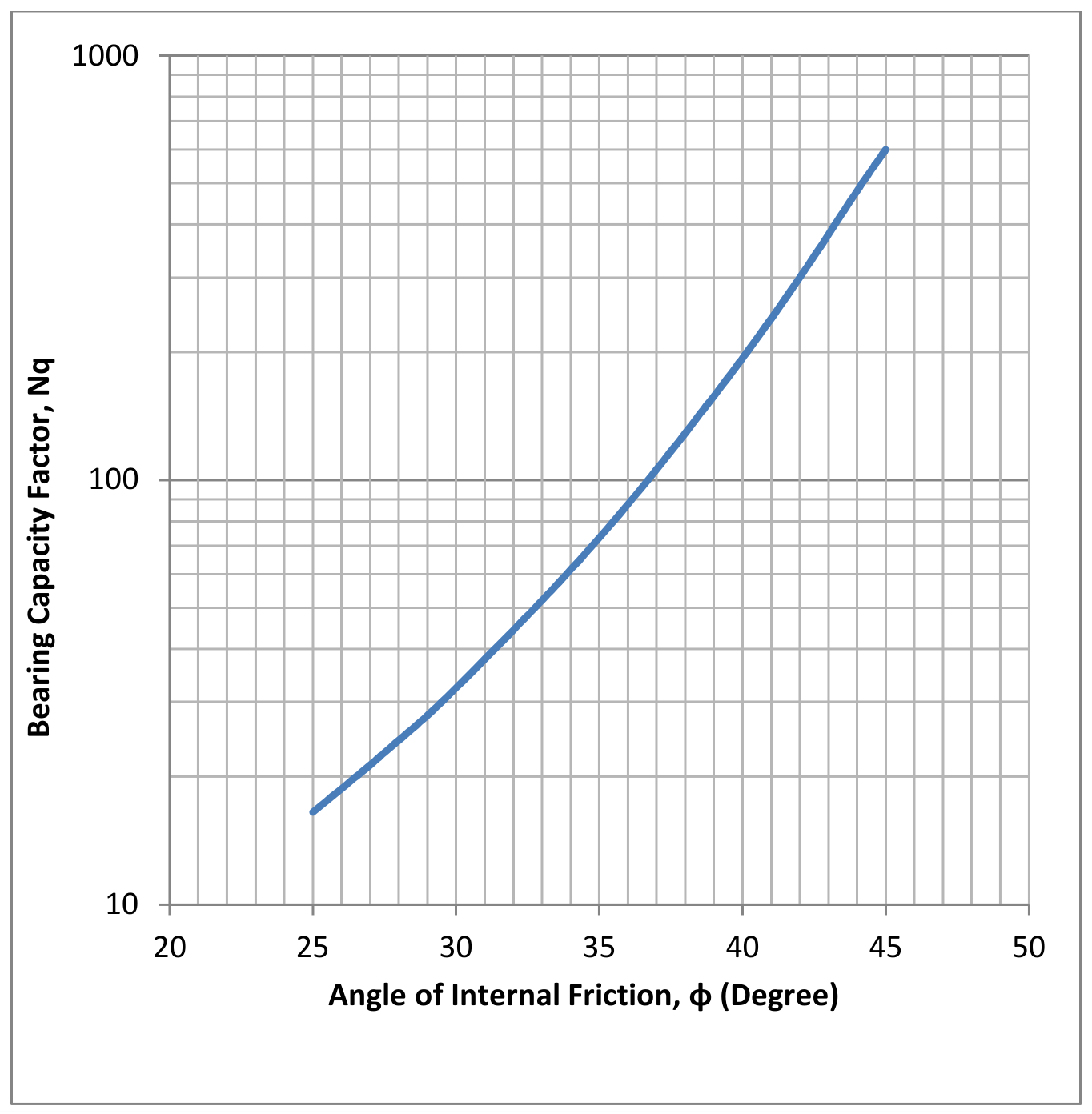
Figure 6.3.2 Bearing capacity factor Nq for deep foundation (After Berezantzev et. al. 1961)
3.10.1.13 Axial Capacity of driven precast pile in cohesive soil using SPT values
Standard Penetration Test N-value is a measure of consistency of clay soil and indirectly the measure of cohesion. The skin friction of pile can thus be estimated from N-value. The following relation may be used for preliminary design of ultimate capacity of concrete piles in clay soil. For skin friction the relationship is as under. For end bearing, the relationship is as under. Where, :_ º= is the average N-value over the pile shaft length and :º= is the N-value in the vicinity of pile tip. A factor of safety of 3.5 shall be used to estimate allowable capacity.3.10.1.14 Axial capacity of driven precast pile in cohesionless soil using static bearing capacity equations
Piles in cohesionless soils shall be designed by effective stress methods of analysis for drained loading conditions. The ultimate axial capacity of piles in cohesionless soils may also be calculated using empirical effective stress method or from in-situ methods and analysis such as the cone penetration or pressure meter tests. Dynamic formula may be used for driven piles in cohesionless soils such as gravels, coarse sand and deposits where pore pressure developed due to driving is quickly dissipated. For piles in cohesionless soil, the ultimate side resistance may be estimated using the following formula: Where, is the effective vertical stress at the level under consideration. The values for β are as under. For uncemented calcareous sand the value of c varies from 0.05 to 0.10. The following equation, as used for cohesive soil, may be used to compute the ultimate end bearing capacity of piles in sandy soil in which, the maximum effective stress, allowed for the computation is 240 kPa. Figure 6.3.2 may also be used to estimate the value of :>.3.10.1.15 Critical depth for end bearing and skin friction
The vertical effective stress ( or ) increases with depth. Hence the skin friction should increase with depth indefinitely. In reality skin friction does not increase indefinitely. It is believed that skin friction would become a constant at a certain depth. This depth is named critical depth. Pile end bearing in sandy soils is also related to effective stress. Experimental data indicates that end bearing capacity does not also increase with depth indefinitely. Due to lack of a valid theory, Engineers use the same critical depth concept adopted for skin friction for end bearing capacity as well. Both the skin friction and the end bearing capacity are assumed to increase till the critical depth, #+ and then maintain a constant value. Following approximations may be used for the critical depth in relation to diameter of pile, D. 5 10# for loose sand #+ 5 15# for medium dense sand #+ 5 20# for dense sand3.10.1.16 Axial Capacity of Driven Precast Pile in Cohesionless Soil using SPT Values
Standard Penetration Test N-value is a measure of relative density hence angle of internal friction of cohesionless soil. The skin friction of pile can thus be estimated from N-value. The following relation may be used for ultimate capacity of concrete piles in cohesionless soil and non-plastic silt. For skin friction the relationship is as under. For sand: For non-plastic silt: For end bearing, the relationship is as under. For sand: For non-plastic silt: Where, :_ º= is the average N-value over the pile shaft length and :º= is the N-value in the vicinity of pile tip. A higher factor of safety of 3.5 should be used to estimate allowable capacity.3.10.1.17 Axial capacity of driven precast pile using pile load Test
Generally, the load on test pile to determine ultimate capacity is twice the design load. The test load on service/working pile is 1.5 times the design load. The following criteria should be met in deciding the allowable/safe pile capacity. Safe Load for Single Pile- (a) Two thirds of the final load at which the load displacement attains a value of 12 mm unless otherwise required in a given case on the basis of nature and type of structure in which case, the safe load should be corresponding to the stated total displacement permissible.
- (b) Fifty (50) percent of the final load at which the total displacement equals to 10 percent of pile diameter case of uniform diameter piles and 7.5 percent of bulb diameter in case of under-reamed piles.
- (a) Final load at which the load displacement attains a value of 25 mm unless otherwise required in a given case on the basis of nature and type of structure, and
- (b) Two thirds of the final load at which the total displacement attains a value of 40 mm.
3.10.1.18 Selection of factor of safety for driven precast pile
Driven pile in soil shall be designed for a minimum overall factor of safety of 2.0 against bearing capacity failure (end bearing, side resistance or combined) when the design is based on the results of a load test conducted at the site, with good quality control. Otherwise, it shall be designed for a minimum factor of safety 3.0. The minimum recommended overall factor of safety is based on an assumed normal level of field quality control during construction. If a normal level of field quality control cannot be assured, higher minimum factors of safety shall be used. The recommended values of overall factor of safety on ultimate axial load capacity based on specified construction control is given in Tables 6.3.10a and 6.3.10b. Partial factor of safety may be used independently for skin friction and end bearing. The values of partial factor of safety may be taken as 1.5 and 3.0 respectively for skin friction and end bearing. The design/allowable load may be taken as the minimum of the values considering overall and partial factor of safety. Table 6.3.10a: Factor of Safety for Deep Foundation for Downward and Upward Load3.10.1.19 Group piles and group capacity of driven precast piles
All piles shall be braced to provide lateral stability in all directions. Three or more piles connected by a rigid cap shall be considered as being braced (stable), provided that the piles are located in a radial direction from the centroid of the group, not less than 60o apart circumferentially. A two pile group in a rigid cap shall be considered to be braced along the axis connecting the two piles. Piles supporting walls shall be driven alternately in lines at least 300 mm apart and located symmetrically under the centre of gravity of the wall load, unless effective measures are taken to cater for eccentricity and lateral forces, or the wall piles are adequately braced to provide lateral stability. Individual piles are considered stable if the pile tops are laterally braced in two directions by construction, such as a structural floor slab, grade beams, struts, or walls. Group pile capacity of driven piles should be determined as the product of the group efficiency, number of piles in the group and the capacity of a single pile. In general, a group efficiency value of 1.0 should be used except for friction piles driven in cohesive soils. The minimum center-to-center pile spacing of 2.5B is recommended. The nominal dimensions and length of all the piles in a group should be similar.3.10.1.20 Pile caps
Pile caps shall be of reinforced concrete. The soil immediately below the pile cap shall not be considered as carrying any vertical load. The tops of all piles shall be embedded not less than 75 mm into pile caps and the cap shall extend at least 100 mm beyond the edge of all piles. The tops of all piles shall be cut back to sound material before capping. The pile cap shall be rigid enough, so that the imposed load can be distributed on the piles in a group equitably. The cap shall generally be cast over a 75 mm thick levelling course of concrete. The clear cover for the main reinforcement in the cap slab under such condition shall not be less than 50 mm.3.10.1.21 Lateral load capacity on driven precast piles
Lateral capacity of vertical single piles shall be the least of the values calculated on the basis of soil failure, structural capacity of the pile and deflection of the pile head. In the analysis, pile head conditions (fixed-head or free-head) should be considered. For estimating the depth of fixity, established method of analysis shall be used. The main reinforcement of pile foundation is usually governed by the lateral load capacity and vice versa. Deflection calculations require horizontal subgrade modulus of the surrounding soil. When considering lateral load on piles, the effect of other coexistent loads, including axial load on the pile, shall be taken into consideration for checking structural capacity of the shaft. To determine lateral load capacity, lateral load tests shall be performed with at least two times the proposed design working load. Allowable lateral load capacity will be the least from the following criteria.- (i) Half of the lateral load at which lateral movement of the pile head is 12 mm or lateral load corresponding to any other specified displacement as per performance requirements.
- (ii) Final load at which the total displacement corresponds to 5 mm or lateral load corresponding to any other specified displacement as per performance requirements.
3.10.1.22 Vertical ground movement and negative skin friction in driven precast piles
The potential for external loading on a pile by vertical ground movements shall be considered as part of the design. Vertical ground movements may result in negative skin friction or downdrag loads due to settlement of compressible soils or may result in uplift loads due to heave of expansive soils. For design purposes, the full magnitude of maximum vertical ground movement shall be assumed. Driven piles installed in compressible fill or soft soil subject to compression shall be designed against downward load due to downdrag. The potential for external loading on a pile by negative skin friction/downdrag due to settlement of compressible soil shall be considered as a part of the design load. Evaluation of negative skin friction shall include a load-transfer method of analysis to determine the neutral point (i.e., point of zero relative displacement) and load distribution along shaft. Due to the possible time dependence associated with vertical ground movement, the analysis shall consider the effect of time on load transfer between the ground and shaft and the analysis shall be performed for the time period relating to the maximum axial load transfer to the pile. Negative skin friction loads may be reduced by application of bitumen or other viscous coatings to the pile surfaces. In estimating negative skin friction the following factors shall be considered :- (i) Relative movement between soil and pile shaft.
- (ii) Relative movement between any underlying compressible soil and pile shaft.
- (iii) Elastic compression of the pile under the working load.
- (iv) The rate of consolidation of the compressible layer.
- (v) Negative skin friction is mobilized only when tendency for relative movement between pile shaft and surrounding soil exists.
3.10.1.23 Driven precast pile in expansive soils (upward movement)
Piles driven in swelling soils may be subjected to uplift forces in the zone of seasonal moisture change. Piles shall extend a sufficient distance into moisture-stable soils to provide adequate resistance to swelling uplift forces. In addition, sufficient clearance shall be provided between the ground surface and the underside of pile caps or grade beams to preclude the application of uplift loads at the pile cap. Uplift loads may be reduced by application of bitumen or other viscous coatings to the pile surface in the swelling zone.3.10.1.24 Dynamic/Seismic Design of Driven Precast Pile
In case of submerged loose sands, vibration caused by earthquake may cause liquefaction or excessive total and differential settlements. This aspect of the problem shall be investigated and appropriate methods of improvements should be adopted to achieve suitable values of N . Alternatively, large diameter drilled pier foundation shall be provided and taken to depths well into the layers which are not likely to liquefy.3.10.1.25 Protection against corrosion and abrasion in driven precast pile
Where conditions of exposure warrant a concrete encasement or other corrosion protections shall be used on steel piles and steel shells. Exposed steel piles or steel shells shall not he used in salt or brackish water, and only with caution in fresh water. Details are given in Sec 3.6.2.3.10.1.26 Dynamic monitoring of driven precast pile
Dynamic monitoring may be specified for piles installed in difficult subsurface conditions such as soils with obstructions and boulders to evaluate compliance with structural pile capacity. Dynamic monitoring may also be considered for geotechnical capacity verification, where the size of the project or other limitations deters static load testing.3.10.1.27 Maximum allowable driving stresses in driven precast pile
Maximum allowable driving stresses in pile material for top driven piles shall not exceed 0.9BH (compression), 0.9BH (tension) for steel piles, 0.85B+′ concrete (compression) and 0.7BH steel reinforcement (tension) for concrete piles and 0.85B+′ −B!+ (compression) for prestressed concrete piles.3.10.1.28 Effect of buoyancy in driven precast pile
The effects of hydrostatic pressure shall be considered in the design of driven piles, where used with foundation subjected to buoyancy forces.3.10.1.29 Protection against Deterioration of Driven Precast Piles
- (a) Steel Pile
3.10.1.30 Pile spacing, clearance and embedment in driven precast pile
End bearing driven piles shall be proportioned such that the minimum center-tocenter pile spacing shall exceed the greater of 750 mm or 2.5 pile diameters/widths. The distance from the side of any pile to the nearest edge of the pile cap shall not be less than 100 mm. The spacing of piles shall be that the average load on the supporting strata will not exceed the safe bearing value of those strata as determined by test boring or other established methods. Piles deriving their capacity from frictional resistance shall be sufficiently apart to ensure that the zones of soil from which the piles derive their support do not overlap to such an extent that their bearing values are reduced. Generally, in such cases, the spacing shall not be less than 3.0 times the diameter of the shaft. The tops of piles shall project not less than 75 mm into concrete after all damaged pile material has been removed.3.10.1.31 Structural capacity of driven precast pile section
The cross-section of driven piles shall be of sufficient size and pile material shall have the necessary structural strength to resist all handling stresses during driving or installation and the necessary strength to transmit the load imposed on them to the underlying and surrounding soil. Pile diameter/cross-section of a pile shaft at any level shall not be less than the designated nominal diameter/cross-section. The structural design of piles must consider each of the following loading conditions.- (i) Handling loads are those imposed on the pile between the time it is fabricated and the time it is in the pile driver leads and ready to be driven. They are generated by cranes, forklifts, and other construction equipment.
- (ii) Driving loads are produced by the pile hammer during driving.
- (iii) Service loads are the design loads from the completed structures.
- Withstand handling stresses
- Endure driving stresses
- Provide the necessary structural capacity
- (i) Pile length < 30 times the least width : 1.00%
- (ii) Pile length 30 to 40 times the least width : 1.5%
- (iii) Pile length > 40 times the least width : 2%
- (i) At each end of the pile for a distance of about three times the least width/diameter – not less than 0.4% of the gross volume of the pile.
- (ii) In the body of the pile – not less than 0.2% of the gross volume of the pile.
- (iii) The transition between closer spacing and the maximum should be gradual over a length of 3 times the least width/diameter.
- (i) For hard driving (driving stress > 1000 kN/m2 ) – 28 MPa
- (ii) For easy driving (driving stress ≤ 1000 kN/m2 ) – 21 MPa
3.10.2 Driven Cast-in-Place Concrete Piles
Driven cast-in-place concrete piles shall be in general cast in metal shells driven into the soil that will remain permanently in place. However, other types of cast-in-place piles, plain or reinforced, cased or uncased, may be used if the soil conditions permit their use and if their design and method of placing are satisfactory.3.10.2.1 Shape
Cast-in-place concrete piles may have a uniform cross-section or may be tapered over any portion.3.10.2.2 Minimum area
The minimum area at the butt of the pile shall be 650 cm2 and the minimum diameter at the tip of the pile shall be 200 mm.3.10.2.3 General reinforcement requirements
Depending on the driving and installation conditions and the loading condition, the amount of reinforcement and its arrangement shall vary. Cast-in-place piles, carrying axial loads only, where the possibility of lateral forces being applied to the piles is insignificant, need not be reinforced where the soil provides adequate lateral support. Those portions of cast-in-place concrete piles that are not supported laterally shall be designed as reinforced concrete columns and the reinforcing steel shall extend 3000 mm below the plane where the soil provides adequate lateral restraint. Where the shell is smooth pipe and more than 3 mm in thickness, it may be considered as load carrying in the absence of corrosion. Where the shell is corrugated and is at least 2 mm in thickness, it may be considered as providing confinement in the absence of corrosion.3.10.2.4 Reinforcement in superstructure
Sufficient reinforcement shall be provided at the junction of the pile with the superstructure to make a suitable connection. The embedment of the reinforcement into the cap shall be as specified for precast piles.3.10.2.5 Shell requirements
The shell shall be of sufficient thickness and strength, so as to hold its original form and show no harmful distortion after it and adjacent shells had driven and the driving core, if any, has been withdrawn. The plans shall stipulate that alternative designs of the shell must be approved by the Engineer before driving is done.3.10.2.6 Splices
Piles may be spliced provided the splice develops the full strength of the pile. Splices should be detailed on the contract plans. Any alternative method of splicing providing equal results may be considered for approval.3.10.2.7 Reinforcement cover
The reinforcement shall be placed a clear distance of not less than 50 mm from the cased or uncased sides. When piles are in corrosive or marine environments, or when concrete is placed by the water or slurry displacement methods, the clear distance shall not be less than 75 mm for uncased piles and piles with shells not sufficiently corrosion resistant. Reinforcements shall extend to within 100 mm of the edge of the pile cap.3.10.2.8 Installation
Steel cased piles shall have the steel shell mandrel driven their full length in contact with surrounding soil, left permanently in place and filled with concrete. No pile shall be driven within 4.5 times the average pile diameter of a pile filled with concrete less than 24 hours old. Concrete shall not be placed in steel shells within the heave range of driving.3.10.2.9 Concreting
For bored or driven cast-in-situ piles, concrete shall be deposited in such a way as to preclude segregation. Concrete shall be deposited continuously until it is brought to the required level. The top surface shall be maintained as level as possible and the formation of seams shall be avoided. For under-reamed piles, the slump of concrete shall range between 100 mm and 150 mm for concreting in water free holes. For large diameter holes concrete may be placed by tremie or by drop bottom bucket; for small diameter boreholes a tremie shall be utilized. A slump of 125 mm to 200 mm shall be maintained for concreting by tremie. In case of tremie concreting for piles of smaller diameter and length up to 10 m, the minimum cement content shall be 350 kg/m3 of concrete. For larger diameter and/or deeper piles, the minimum cement content shall be 400 kg/m3 of concrete. For concreting under water, the concrete shall contain at least 10 percent more cement than that required for the same mix placed in the dry. The amount of coarse aggregate shall be not less than one and a half times, nor more than two times, that of the fine aggregate. The materials shall be so proportioned as to produce a concrete having a slump of not less than 125 mm, nor more than 200 mm.3.10.2.10 Structural integrity
Bored piles shall be installed in such a manner and sequence as to prevent distortion or damage to piles being installed or already in place, to the extent that such distortion or damage affects the structural integrity of pile.3.10.3 Prestressed Concrete Piles
3.10.3.1 Shape and size
Prestressed concrete piles that are generally octagonal, square or circular shall be of approved size and shape. Concrete in prestressed piles shall have a minimum compressive strength (cylinder), B+′ of 35 MPa at 28 days. Prestressed concrete piles may be solid or hollow. For hollow piles, precautionary measures should be taken to prevent breakage due to internal water pressure during driving.3.10.3.2 Reinforcement
Within the context of this Code, longitudinal prestressing is not considered as loadbearing reinforcement. Sufficient prestressing steel in the form of high-tensile wire, strand, or bar should be used so that the effective prestress after losses is sufficient to resist the handling, driving, and service-load stresses. Post-tensioned piles are cast with sufficient mild steel reinforcement to resist handling stresses before stressing. For pretensioned piles, the longitudinal prestressing steel should be enclosed in a steel spiral with the minimum wire size ranging from ACI 318 W3.5 (nominal area 0.035 in2 , nominal dia=0.211 inch) to W5 (nominal area 0.05 in2 , nominal dia=0.252 inch) depending on the pile size. The wire spiral should have a maximum 6 in. (150 mm) pitch with closer spacing at each end of the pile and several close turns at the tip and pile head. The close spacing should extend over at least twice the diameter or thickness of the pile, and the few turns near the ends are often at 1 in. (25 mm) spacing. Occasionally, prestressed piles are designed and constructed with conventional reinforcement in addition to the prestressing steel to increase the structural capacity and ductility of the pile. This reinforcement reduces the stresses in the concrete and should be taken into account. For prestressed concrete piles, the effective prestress after all losses should not be less than 700 lb/in2 (4.8 MPa). Significantly higher effective prestress values are commonly used and may be necessary to control driving stresses in some situations. Bending stresses shall be investigated for all conditions of handling, taking into account the weight of the pile plus 50 percent allowance for impact, with tensile stresses limited to .3.10.3.3 Vertical and spiral reinforcement
The full length of vertical reinforcement shall be enclosed within spiral reinforcement. For piles up to 600 mm in diameter, spiral wire shall be No.5 (U.S. Steel Wire Gage). Spiral reinforcement at the ends of these piles shall have a pitch of 75 mm for approximately 16 turns. In addition, the top 150 mm of pile shall have five turns of spiral winding at 25 mm pitch. For the remainder of the pile, the vertical steel shall be enclosed with spiral reinforcement with not more than 150 mm pitch. For piles having diameters greater than 600 mm. spiral wire shall be No.4 (U.S. Steel Wire Gauge). Spiral reinforcement at the end of these piles shall have a pitch of 50 mm for approximately 16 turns. In addition, the top 150 mm of pile shall have four turns of spiral winding at 38 mm pitch. For the remainder of the pile, the vertical steel shall be enclosed with spiral reinforcement with not more than 100 mm pitch. The reinforcement shall be placed at a clear distance from the face of the prestressed pile of not less than 50 mm.3.10.3.4 Driving and handling stresses
A prestressed pile shall not be driven before the concrete has attained a compressive strength of at least 28 MPa, but not less than such strength sufficient to withstand handling and driving forces.3.10.4 Bored Piles
In bored cast in place piles, the holes are first bored with a permanent or temporary casing or by using bentonite slurry to stabilize the sides of the bore. A prefabricated steel cage is then lowered into the hole and concreting is carried by tremie method.3.10.4.1 Shape and size
Bored cast-in-situ concrete piles that are generally circular in section shall be of approved size and shape. Concrete in bored cast-in-situ concrete piles shall have a minimum compressive strength (cylinder), B+′ of 21 MPa at 28 days.3.10.4.2 Dimension
All shafts should be sized in 50 mm increments with a minimum shaft diameter of 400 mm.3.10.4.3 Ultimate geotechnical capacity of bored pile for axial load
The basic concept of ultimate bearing capacity and useful equations for axial load capacity are identical to that of driven pile as described in Art. 3.10.1.10.3.10.4.4 Axial capacity of bored piles in cohesive soil using static bearing capacity equations
The ultimate axial capacity of bored piles in cohesive may be calculated from the same static formula as used for driven piles, given by Equations 6.3.14a, 6.3.14b and 6.3.15, using a total stress method for undrained loading conditions, or an effective stress method for drained loading conditions. The skin friction B may be taken as 2/3rd the value of driven piles and the end bearing B4 may be taken as 1/3rd of that of driven pile.3.10.4.5 Axial capacity of bored piles in cohesive soil using SPT values
The following relations may be used for preliminary design of ultimate capacity of concrete bored piles in clay soils. For skin friction the relationship is as under. For end bearing, the relationship is as under. Where, :_ º= is the average N-value over the pile shaft length and :º= is the N-value in the vicinity of pile tip. A higher factor of safety of 3.5 should be used to estimate allowable capacity.3.10.4.6 Axial capacity of bored piles in cohesionless soil using static bearing
The ultimate axial capacity of bored piles in cohesive soil may be calculated from the same static formula as used for driven piles described in Sec 3.10.1.10. The skin friction B may be taken as 2/3rd the value of driven pile and the end bearing B4 may be taken as 1/3rd of driven pile. Critical Depth for End Bearing and Skin Friction Similar to driven piles, following approximations may be used for the critical depth in relation to pile diameter, D.3.10.4.7 Axial capacity of bored piles in cohesionless soil using SPT values
The following relations may be used for preliminary design of ultimate capacity of concrete bored piles in sand and non-plastic silty soils. For skin friction the relationship is as under : For sand For non-plastic silt: For end bearing, the relationship is as under. For sand For non-plastic silt: Where, N 60 is the average N-value over the pile shaft length and N60 is the N-value in the vicinity of pile tip (down to a depth of 3D). A higher factor of safety of 3.5 should be used to estimate allowable capacity.3.10.4.8 Axial capacity of bored pile using pile load test
The procedures and principles of pile load test for ultimate capacity are similar to that of driven piles.3.10.4.9 Structural capacity of bored concrete pile/drilled shaft
Minimum Reinforcement in Bored Concrete Pile For piles loaded in compression alone, it is generally only necessary to reinforce the shaft to a depth of 2 m greater than the depth of temporary casing to prevent any tendency for concrete lifting when pulling the casing. Piles subject to tension or lateral forces and eccentric loading (possibly being out of position or out of plumb) do however require reinforcement suitable to cope with these forces. The following criteria for typical nominal reinforcement for piles in compression shall be considered. Table 6.3.11 may be used as guidelines. The restrictions that apply to the use of this Table have to be carefully considered in any particular application. Table 6.3.11: Guidance on the Minimum Reinforcing Steel for Bored Cast-in-place Piles- (a) Yield strength of steel = 420 MN/m2
- (b) The above guidelines are for “build-ability” only: They are not appropriate Where:
- (i) Piles are required to resist any applied tensile or bending forces- the reinforcement has to be designed for the specific loading conditions.
- (ii) Piles are required to accommodate positional and verticality tolerances, or where they are constructed through very soft alluvial deposits (cu < 10 kN/m2 ). Specific reinforcement design is then necessary.
- (c) Minimum depth of reinforcement is taken as 3 m below cutoff for simple bearing only. Any lateral loads or moments taken by the pile will require reinforcement to extend to some depth below the zone subjected to bending forces. This zone may be determined from a plot of the bending moment with depth. Furthermore the reinforcement would normally extend at least 1 m below the depth of any temporary casing.
- (d) Even with the appropriate reinforcement care will still be required to prevent damage to piles by construction activities especially during cutting-down or in the presence of site traffic.
3.10.4.10 Selection of factor of safety for bored pile
Selection of factor of safety for axial capacity of bored pile is similar to that used for driven piles.3.10.4.11 Group capacity of bored pile
The behavior of group bored piles is almost similar to that of driven piles. For the pile cap, lateral load capacity, vertical ground movement, negative skin friction, piles in expansive soil, dynamic and seismic design, corrosion protection, dynamic monitoring and buoyancy. Sec 3.10.1.18 should be consulted as they are similar for both driven and bored piles. However, Individual bored piles are considered stable if the pile tops are laterally braced in two directions by construction, such as a structural floor slab, grade beams, struts, or walls. Generally, the use of a single pile as foundation is not recommended unless the diameter is 600 mm or more.3.10.5 Settlement of Driven and Bored Piles
The settlement of axially loaded piles and pile groups at the allowable loads shall be estimated. Elastic analysis, load transfer and/or finite element techniques may be used. The settlement of the pile or pile group shall not exceed the tolerable movement limits as recommended for shallow foundations (Table 6.3.7). When a pile is loaded, two things would happen involving settlement.- The pile would settle into the soil
- The pile material would compress due to load
- Settlement due to axial deformation,
- Settlement at the pile tip,
- Settlement due to skin friction, C
- C”()Ð<) 5 + + C (6.3.35a)
Short term or elastic pile group settlement can be estimated using the following relation.
Where,
C = Settlement of the pile group
= Diameter of the pile
Interestingly, geometry of the group does not have much of an influence on the settlement. As such, Group Settlement Ratio, @ of a pile group consisting of n number of piles can be approximated as follows :
The settlement of the group can be estimated as the highest value as obtained from Equations 6.3.37 and 6.3.38.
Long Term Settlement for Pile Group
For pile groups, settlement due to consolidation is more important than for single piles. Consolidation settlement of pile group in clay soil is computed using the following simplified assumptions.
- The pile group is assumed to be a solid foundation with a depth 2/3rd the length of the piles
- Effective stress at mid-point of the clay layer is used to compute settlement
- = Compression index of soil
- = Thickness of the clay layer
- = Thickness of the clay layer
- σ′ = Initial effective stress at mid-point of the clay layer
- σ1 ′ = New effective stress at mid-point of the clay layer after pile load.
- σ7′ = Reference stress (100 kPa)
- 9 = Dimensionless modulus number as obtained from Table 6.3.14
- d = Stress exponent as obtained from Table 6.3.14.
3.10.6 Drilled Shafts/ Drilled Piers
Large diameter (more than 600 mm) bored piles are sometimes classified as drilled shaft or drilled piers. They are usually provided with enlarged base called bell. The provisions of this article shall apply to the design of axially and laterally loaded drilled shafts/ drilled piers in soil or extending through soil to or into rock.3.10.6.1 Application of drilled shaft
Drilled shafts may be considered when spread footings cannot be founded on suitable soil within a reasonable depth and when piles are not economically viable due to high loads or obstructions to driving. Drilled shafts may be used in lieu of spread footings as a protection against scour. Drilled shafts may also be considered to resist high lateral or uplift loads when deformation tolerances are small.3.10.6.2 Materials for drilled shaft
Shafts shall be cast-in-place concrete and may include deformed bar steel reinforcement, structural steel sections, and/or permanent steel casing as required by design.3.10.6.3 Embedment for Drilled Shaft
Shaft embedment shall be determined based on vertical and lateral load capacities of both the shaft and sub-surface materials.3.10.6.4 Batter drilled shaft
The use of battered shafts to increase the lateral capacity of foundations is not recommended due to their difficulty of construction and high cost. Instead, consideration should first be given to increasing the shaft diameter to obtain the required lateral capacity.3.10.6.5 Selection of soil properties for drilled shaft
Soil and rock properties defining the strength and compressibility characteristics of the foundation materials are required for drilled shaft design.3.10.6.6 Geotechnical design of drilled shafts
Drilled shafts shall be designed to support the design loads with adequate bearing and structural capacity, and with tolerable settlements. The response of drilled shafts subjected to seismic and dynamic loads shall also be evaluated. Shaft design shall be based on working stress principles using maximum un-factored loads derived from calculations of dead and live loads from superstructures, substructures, earth (i.e., sloping ground), wind and traffic. Allowable axial and lateral loads may be determined by separate methods of analysis. The design methods presented herein for determining axial load capacity assume drilled shafts of uniform cross section, with vertical alignment, concentric axial loading, and a relatively horizontal ground surface. The effects of an enlarged base, group action, and sloping ground are treated separately.3.10.6.7 Bearing capacity equations for drilled shaft
The ultimate axial capacity of drilled shafts shall be determined in accordance with the principles laid for bored piles. Cohesive Soil Skin friction resistance in cohesive soil may be determined using either the α-method or the β-method as described in the relevant section of driven piles. However, for clay soil, α-method has wide been used by the engineers. This method gives: Where,- = Skin friction
- = undrained shear strength of soil along the shaft
Figure 6.3.3 Adhesion factor α for drilled shaft (after Kulhawy and Jackson, 1989)
Where,
B4 = Unit bearing resistance
N = Mean SPT value for the soil between the base of the shaft and a depth equal to two times the base diameter below the base. No overburden correction is required (N= N60)
If the base diameter is more than 1200 mm, the value of B4 from Eq. 6.3.48 could produce settlements greater than 25 mm, which would be unacceptable for most buildings. To keep settlement within tolerable limits, the value of B4 should be reduced to B4 ′ by multiplying a factor &7 such that:
Where,
4 =Base diameter of drilled shaft
3.10.6.8 Other methods of evaluating axial load capacity of drilled shaft
A number of other methods are available to estimate the ultimate axial load capacity of drilled shafts. These methods are based on N-values obtained from Standard Penetration Test (SPT) and on angle of internal friction of sand. These methods may also be used to estimate the ultimate load carrying capacity of drilled shafts. Three of these methods are as follows and they are summarized in Appendix G.- Method based on the Standard Penetration Test (CGS, 1985)
- Method based on Theory of Plasticity (CGS, 1985)
- Tomlinson (1995) Method
3.10.6.9 Factor of safety for drilled shaft
Similar to bored and driven piles, drilled shafts shall be designed for a minimum overall factor of safety of 2.0 against bearing capacity failure (end bearing, side resistance or combined) when the design is based on the results of a load test conducted at the site. Otherwise, it shall be designed for a minimum overall factor of safety 3.0. The minimum recommended overall factor of safety is based on an assumed normal level of field quality control during construction. If a normal level of field quality control cannot be assured, higher minimum factors of safety shall be used. The recommended values of overall factor of safety on ultimate axial load capacity based on specified construction control is presented in Tables 6.3.10a and 6.3.10b.3.10.6.10 Deformation and settlement of axially loaded drilled shaft
Similar to driven and bored piles, settlement of axially loaded shafts at working or allowable loads shall be estimated using elastic or load transfer analysis methods. For most cases, elastic analysis will be applicable for design provided the stress levels in the shaft are moderate relative to . Analytical methods are similar to that provided in Sec 3.10.1.10 for driven and bored piles. The charts provided in Appendix G may also be used to estimate the settlement of drilled shaft.3.10.6.11 Drilled shaft in layered soil profile
The short-term settlement of shafts in a layered soil profile may be estimated by summing the proportional settlement components from layers of cohesive and cohesionless soil comprising the subsurface profile.3.10.6.12 Tolerable movement of drilled shaft
Tolerable axial displacement criteria for drilled shaft foundations shall be developed by the structural designer consistent with the function and type of structure, fixity of bearings, anticipated service life, and consequences of unacceptable displacements on the structure performance. Drilled shaft displacement analyses shall be based on the results of in-situ/laboratory testing to characterize the load-deformation behavior of the foundation materials.3.10.6.13 Group loading of drilled shaft
Cohesive Soil Evaluation of group capacity of shafts in cohesive soil shall consider the presence and contact of a cap with the ground surface and the spacing between adjacent shafts. For a shaft group with a cap in firm contact with the ground, may be computed as the lesser of (1) the sum of the individual capacities of each shaft in the group or (2) the capacity of an equivalent pier defined in the perimeter area of the group. For the equivalent pier, the shear strength of soil shall not be reduced by any factor (e.g., α1) to determine the ? component of , the total base area of the equivalent pier shall be used to determine the QT component of and the additional capacity of the cap shall be ignored. If the cap is not in firm contact with the ground, or if the soil at the surface is loose or soft, the individual capacity of each shaft should be reduced to ζ times QT for an isolated shaft, where ζ = 0.67 for a center-to-center (CTC) spacing of 3B (where B is the shaft diameter) and ζ = 1.0 for a CTC spacing of 6B. For intermediate spacings, the value of ζ may be determined by linear interpolation. The group capacity may then be computed as the lesser of (1) the sum of the modified individual capacities of each shaft in group, or (2) the capacity of an equivalent pier as stated above. Cohesionless Soil Evaluation of group capacity of shafts in cohesion soil shall consider the spacing between adjacent shafts. Regardless of cap contact with the ground, the individual capacity of each shaft should be reduced to times QT for an isolated shaft, where ζ = 0.67 for a center-lo-center (CTC) spacing of 3B and ζ = 1.0 for a CTC spacing of 8B. For intermediate spacings, the value of ζ may be determined by linear interpolation. The group capacity may be computed as the lesser of (I) sum of the modified individual capacities of each shaft in the group or (2) capacity of an equivalent pier circumscribing the group including resistance over the entire perimeter and base areas.3.10.6.14 Drilled shaft in strong soil overlying weak soil
If a group of shafts is embedded in a strong soil deposit which overlies a weaker deposit (cohesionless and cohesive soil), consideration shall be given to the potential for a punching failure of the lip into the weaker soil strata. For this case, the unit tip capacity XH of the equivalent shaft may be determined using the following: In the above equation X^A is the ultimate unit capacity of an equivalent shaft bearing in the stronger upper layer and XB is the ultimate unit capacity of an equivalent shaft bearing in the weaker underlying soil layer. If the underlying soil unit is a weaker cohesive soil strata, careful consideration shall be given to the potential for large settlements in the weaker layer.3.10.6.15 Lateral loads on drilled shaft
Soil Layering The design of laterally loaded drilled shafts in layered soils shall be based on evaluation of the soil parameters characteristic of the respective layers Ground Water The highest anticipated water level shall be used for design Scour The potential for loss of lateral capacity due to scour shall be considered in the design. If heavy scour is expected, consideration shall be given to designing the portion of the shaft that would be exposed as a column. In all cases, the shaft length shall be determined such that the design structural load can be safely supported entirely below the probable scour depth. Group action There is no reliable rational method for evaluating the group action for closely spaced, laterally loaded shafts. Therefore, as a general guide, drilled shaft with diameter B in a group may be considered to act individually when the center-tocenter (CTC) spacing is greater than 2.5B in the direction normal to loading, and CTC > 8B in the direction parallel to loading. For shaft layout not conforming to these criteria, the effects of shaft interaction shall be considered in the design. As a general guide, the effects of group action for in-line CTC <8B may be considered using the ratios (CGS, 1985) appearing as below, Table 6.3.16: Table 6.3.16: Ratio of Group and Single Plie Shaft Resistance
The effects of traffic, wind, and other non-seismic cyclic loading on the loaddeformation behavior of laterally loaded drilled shafts shall be considered during design. Analysis of drilled shafts subjected to cyclic loading may he considered in the COM624 analysis (Reese et. al., 1984).
Combined Axial and Lateral Loading
The effects of lateral loading in combination with axial loading shall be considered in the design. Analysis of drilled shafts subjected to combined loading may be considered in the COM624 analysis (Reese et. al., 1984).
Sloping Ground
For drilled shafts which extend through or below sloping ground. The potential for additional lateral loading shall be considered in the design. The general method of analysis developed by Borden and Gabr (1987) may be used for the analysis of shafts instable slopes. For shafts in marginally stable slopes. Additional consideration should be given for smaller factors of safety against slope failure or slopes showing ground creep, or when shafts extend through fills overlying soft foundation soils and bear into more competent underlying soil or rock formations. For unstable ground, detailed explorations, testing and analysis are required to evaluate potential additional lateral loads due to slope movements
Tolerable Lateral Movements
Tolerable lateral displacement criteria for drilled shaft foundations shall be developed by the structural designer consistent with the function and type of structure, fixity, anticipated service life, and consequences of unacceptable displacements on the structure performance. Drilled shaft lateral displacement analysis shall be based on the results of in-situ and/or laboratory testing to characterize the load-deformation behavior of the foundation materials.
3.10.6.16 Uplift loads on drilled shaft
Uplift capacity shall rely only on side resistance in conformance with related articles for driven piles. If the shaft has an enlarged base, ? shall be determined in conformance with related articles for driven piles.3.10.6.17 Consideration of vertical ground movement
The potential for external loading on a shaft by vertical ground movement (i.e., negative skin friction down-drag due to settlement of compressible soil or uplift due to heave of expansive soil) shall be considered as a part of design. For design purposes, it shall be assumed that the full magnitude of maximum potential vertical ground movement occurs.3.10.6.18 Negative skin friction
Evaluation of negative skin friction shall include a load-transfer method of analysis to determine the neutral point (i.e., point of zero relative displacement) and load distribution along shaft (e.g., Reese and O’Neill, 1988). Due to the possible time dependence associated with vertical ground movement, the analysis shall consider the effect of time on load transfer between the ground and shaft and the analysis shall be performed for the time period relating to the maximum axial load transfer to the shaft. Evaluation of negative skin friction shall include a load-transfer method of analysis to determine the neutral point (i.e., point of zero relative displacement) and load distribution along shaft (e.g., Reese and O’Neill, 1988). Due to the possible time dependence associated with vertical ground movement, the analysis shall consider the effect of time on load transfer between the ground and shaft and the analysis shall be performed for the time period relating to maximum axial load transfer to the shaft.3.10.6.19 Expansive soils
Shafts designed for and constructed in expansive soil shall extend to a sufficient depth into moisture-stable soils to provide adequate anchorage to resist uplift movement in addition; sufficient clearance shall be provided between the ground surface and underside of caps or beams connecting shafts to preclude the application of uplift loads at the shaft/cap connection from swelling ground conditions.3.10.6.20 Dynamic/seismic design of drilled shaft
Refer to Seismic Design section of this Code and Lam and Martin (1986a; 1986b) for guidance regarding the design of drilled shafts subjected to dynamic and seismic loads.3.10.6.21 Structural shaft design, shaft dimensions and shaft spacing
Drilled shafts shall be designed to resist failure loads to insure that the shaft will not collapse or suffer loss of serviceability due to excessive stress and/or deformation. Dimensions All shafts should be sized in 50 mm increments with a minimum shaft diameter of 600 mm. The diameter of columns supported by shafts shall be less than or equal to the shaft diameter B. Center to Center Spacing The center-to-center spacing of drilled shafts of diameter B should be 3B or greater to avoid interference between adjacent shafts during construction. If closer spacing is required, the sequence of construction shall be specified and the interaction effects between adjacent shafts shall be evaluated by the designer. Reinforcement Where the potential for lateral loading is insignificant, drilled shafts need to be reinforced for axial loads only. Those portions of drilled shafts that are not supported laterally shall be designed as reinforced concrete columns in accordance with relevant sections in structural design part of the Code and the reinforcing steel shall extend a minimum of 5 m below the plane where the soil provides adequate lateral restraint. Where permanent steel casing is used and the shell is smooth pipe and more than 3 mm in thickness, it may be considered as load carrying in the absence of corrosion. The design of longitudinal and spiral reinforcement shall be in conformance with the requirements of the relevant sections of the structural design part of the Code. Development of length of deformed reinforcement shall be in conformance with the relevant sections of the structural design part of the Code. Longitudinal Bar Spacing The minimum clear distance between longitudinal reinforcement shall not be less than 3 times the bar diameter nor 3 times the maximum aggregate size. If bars are bundled in forming the reinforcing cage, the minimum clear distance between longitudinal reinforcement shall not be less than 3 times the diameter of the bundled bars. Where heavy reinforcement is required, consideration may be given to an inner and outer reinforcing cage. Splices Splices shall develop the full capacity of the bar in tension and compression. The location of splices shall be staggered around the perimeter of the reinforcing cage so as not to occur at the same horizontal plane. Splices may be developed by lapping, welding, and special approved connectors. Splices shall be in conformance with the relevant sections of the structural design part of the Code. Transverse Reinforcement Transverse reinforcement shall be designed to resist stresses caused by fresh concrete flowing from inside the cage to the side of the excavated hole. Transverse reinforcement may be constructed of hoops or spiral steel. Handling Stresses Reinforcement cages shall be designed to resist handling and placement stresses. Reinforcement Cover The reinforcement shall be placed a clear distance of not less than 50 mm from the permanently cased or 75 mm from the uncased sides. When shafts are constructed in corrosive or marine environments, or when concrete is placed by the water or slurry displacement methods, the clear distance shall not be less than 100 mm for uncased shafts and shafts with permanent casings not sufficiently corrosion resistant. The reinforcement cage shall be centered in the hole using centering devices. All steel centering devices shall be epoxy coated. Reinforcement into Superstructure Sufficient reinforcement shall be provided at tit junction of the shaft with the superstructure to make a suitable connection. The embedment of the reinforcement into the cap shall be in conformance with relevant articles of the structural design part of the Code.3.10.6.22 Enlarged base of drilled shaft
Enlarged bases shall be designed to insure that plain concrete is not overstressed. The enlarged base shall slope at a side angle not less than 30 degrees from the vertical and have a bottom diameter not greater than 3 times diameter of the shaft. The thickness of the bottom edge of enlarged base shall not be less than 150 mm.3.10.6.23 Construction of drilled shaft
Drilled shafts may be constructed using the dry, casing, or wet method of construction, or a combination of methods. In every case, excavation of hole, placement of concrete, and all other aspects of shaft construction shall be performed in conformance with the provisions of this Code. The load capacity and deformation behavior of drilled shafts can be greatly affected by the quality and methods of construction. The effects of construction methods are incorporated in design by application of factor of safety consistent with the expected construction methods and level of field quality control measures undertaken as described in the relevant sections for driven piles. Where the spacing between shafts in a group is restricted, consideration shall be given to the sequence of construction to minimize the effect of adjacent shaft construction operations on recently constructed shafts. The following construction procedure shall be followed:- (i) Place permanent/temporary steel casing in position and embed casing toe into firm strata.
- (ii) Bore and excavate inside the steel casing down to casing toe level, or to a level approved, and continue excavation to final pile tip level using drilling mud. The fluid level inside casings shall at all times be at least 2 metres higher than outside the casings.
- (iii) Carefully clean up all mud or sedimentation from the bottom of borehole.
- (iv) Place reinforcement cage, inspection pipes etc.
- (v) Concrete continuously under water, or drilling fluid, by use of the tremie method.
- (vi) After hardening, break out the top section of the concrete pile to reach sound concrete.
Where a borehole is formed using drilling fluid for maintaining the stability of a boring, the level of the water or fluid in the excavation shall be maintained so that the water or fluid pressure always exceeds the pressure exerted by the soils and external ground water. The water or fluid level shall be maintained at a level not less than 2 m above the level of ground water.
The reinforcement shall be placed as indicated on the Drawings. Reinforcement in the form of a cage shall be assembled with additional support, such as Spreader forks and lacings, necessary to form a rigid cage. Hoops, links or helical reinforcement shall fit closely around the main longitudinal bars and be bound to them by approved wire, the ends of which shall be turned into the interior of the pile or pour. Reinforcement shall be placed and maintained in position. The cover to all reinforcement for pile cap and bored cast in place pile shall be not less than 75 mm.
Joints in longitudinal steel bars shall be permitted unless otherwise specified. Joints in reinforcement shall be such that the full strength of the bar is effective across the joint and shall be made so that there is no relative displacement of the reinforcement during the construction of the pile. Joints in longitudinal bars in piles with tension (for instance for test loading) shall be carried out by welding or other approved method.
Concrete to be placed under water or drilling fluid shall be placed by tremie equipment and shall not be discharged freely into the water or drilling fluid. The tremie equipment shall be designed to minimize the occurrence of entrapped air and other voids, so that it causes minimal surface disturbance, which is particularly important when a concrete-water interface exists. It shall be so designed that external projections are minimised, allowing the tremie to pass through reinforcing cages without causing damage. The internal face of the pipe of the tremie shall be free from projections. The tremie pipes shall meet the following requirements:
- (i) The tremie pipes shall be fabricated of heavy gage steel pipe to withstand all anticipated handling stress. Aluminium pipe shall not be used for placing concrete.
- (ii) Tremie pipes should have a diameter large enough to ensure that aggregates-caused blockage will not occur. The diameter of the tremie pipe shall be 200 mm to 300 mm.
- (iii) The tremie pipes shall be smooth internally.
- (iv) Since deep placement of concrete will be carried out, the tremie shall be made in sections/lengths with detachable joints that allow the upper sections/lengths to be removed as the placement progresses.
- (v) Sections may be joined by flanged, bolted connections (with gaskets) or may be screwed together. Whatever joint technique is selected, joints between tremie sections must be watertight. The joint system selected shall be tested for water tightness before beginning of concrete placement.
- (vi) The joint system to be used shall need approval of the Engineer.
- (vii) The tremie pipe should be marked to allow quick determination of the distance from the surface of the water to the mouth of the tremie.
- (viii) The tremie should be provided with adequately sized funnel or hopper to facilitate transfer of sufficient concrete from the delivery device to the tremie.
3.10.6.24 Concreting of drilled shaft
In drilled shafts/cast-in-situ bored piles, concrete shall be placed only after excavation has been completed, inspected and accepted, and steel reinforcement accurately placed and adequately supported. Concrete shall be placed in one continuous operation in such a manner as to ensure the exclusion of any foreign matter and to secure a full sized shaft. Concrete shall not be placed through water except where tremie methods are approved. When depositing concrete from the top of the pile, the concrete shall not be chuted directly into the pile but shall be poured in a rapid and continuous operation through a funnel hopper centred at the top of the pile. For large diameter holes concrete may be placed by tremie or by drop bottom bucket; for small diameter boreholes a tremie shall be utilized. In tremie concreting, toe of the tremie shall be set at a maximum of 150 mm above the bottom of the borehole. Maximum permissible siltation in bore hole prior to start of concrete operation shall be 75 mm. A slump of 125 mm to 150 mm shall be maintained for concreting by tremie. In case of tremie concreting for piles of smaller diameter and length up to 10 m, the minimum cement content shall be 350 kg/m3 of concrete. For larger diameter and/or deeper piles, the minimum cement content shall be 400 kg/m3 of concrete. See relevant sections of the Code for further specification. For uncased concrete piles, if pile shafts are formed through unstable soil and concrete is placed in an open drill hole, a steel liner shall be inserted in the hole prior to placing concrete. If the steel liner is withdrawn during concreting, the level of concrete shall be maintained above the bottom of the liner to a sufficient height to offset any hydrostatic or lateral earth pressure. If concrete is placed by pumping through a hollow stem auger, the auger shall not be permitted to rotate during withdrawal and shall be withdrawn in a steady continuous motion. Concrete pumping pressures shall be measured and shall be maintained high enough at all times to offset hydrostatic and lateral earth pressure. Concrete volumes shall be measured to ensure that the volume of concrete placed in each pile is equal to or greater than the theoretical volume of the hole created by the auger. If the installation process of any pile is interrupted or a loss of concreting pressure occurs, the hole shall be redrilled to original depth and reformed. Augured cast-in-situ pile shall not be installed within 6 pile diameters centre to centre of a pile filled with concrete less than 24 hours old. If concrete level in any completed pile drops, the pile shall be rejected and replaced. Bored cast-in-situ concrete piles shall not be drilled/bored within a clear distance of 3 m from an adjacent pile with concrete less than 48 hours old. For under-reamed piles, the slump of concrete shall range between 100 mm and 150 mm for concreting in water free holes. For concreting under water, the concrete shall contain at least 10 percent more cement than that required for the same mix placed in the dry. The amount of coarse aggregate shall be not less than one and a half times, nor more than two times, that of the fine aggregate. The materials shall be so proportioned as to produce a concrete having a slump of not less than 100 mm, nor more than 150 mm, except where plasticizing admixtures is used in which case, the slump may be 175 mm. Successful placement of concrete under water requires preventing flow of water across or through the placement site. Once flow is controlled, the tremie placement consists of the following three basic steps:- (i) The first concrete placed is physically separated from the water by using a “rabbit” or go-devil in the pipe, or by having the pipe mouth capped or sealed and the pipe dewatered.
- (ii) Once filled with concrete, the pipe is raised slightly to allow the “rabbit” to escape or to break the end seal. Concrete will then flow out and develop a mound around the mouth of the pipe. This is termed as “establishing a seal”.
- (iii) Once the seal is established, fresh concrete is injected into the mass of existing concrete.
3.11 Field Tests for Driven Piles and Drilled Shafts
3.11.1 Integrity Test
Low strain integrity testing of piles is a tool for quality control of long structural elements that function in a manner similar to foundation piles, regardless of their method of installation, provided that they are receptive to low strain impact testing. The test provides velocity (and optionally force) data, which assists evaluation of pile integrity and pile physical dimensions (i.e., cross-sectional area, length), continuity and consistency of pile material. The test does not give any information regarding the pile bearing capacity or about pile reinforcement. Integrity test principles have been well documented in literature (ASTM 5882; Klingmuller, 1993). There exist two methods of integrity testing, namely, Pulse Echo Method (PEM) and Transient Response Method (TRM). In Pulse Echo Method, the pile head motion is measured as a function of time. The time domain record is then evaluated for pile integrity. In Transient Response Method, the pile head motion and force (measured with an instrumented hammer) are measured as a function of time. The data are then evaluated usually in the frequency domain. In order to check the structural integrity of the piles Integrity tests shall be performed on the piles in accordance with the procedure outlined in ASTM D5882. The test is carried out by pressing a transducer onto a pile top while striking the pile head with a hand hammer. The Sonic Integrity Testing (SIT)-system registers the impact of the hammer followed by the response of the pile and shows the display. If instructed by the operator, the signal will be stored in the memory of the SIT-system together with other information, such as pile number, date, time, site, amplification factor, filter length etc. The reflectograms are horizontally scaled and vertically amplified to compensate external soil friction, which facilitate the interpretation. Consequently, the reflection of the pile toe matches the length of the pile which will be confirmed by the SIT-system. In case of any defects, the exact location can be determined from the graph on the display. For any project where pile has been installed, integrity tests shall be performed on 100% of the piles. Integrity testing may not identify all imperfections, but it can be used in identifying major defects within effective length. In literature, there are many examples that highlight success of low strain integrity testing (Klingmuller, 1993).- (a) This sonic echo pile integrity testing or dynamic response method is based on measuring (or observing on an oscilloscope) the time it takes for a reflected compression stress wave to return to the top of the pile.
- (b) Some waves will be reflected by a discontinuity in the pile shaft. When the compressive strength is known for the pile material involved, the depth to the discontinuity and the pile length can be determined.
- (c) On the other hand, area of pile shaft and hence its diameter, is determined from impedance of wave response, while impedance in any section is a function of elastic modulus of pile material, shaft area and wave velocity propagating through that section. If the concrete material is uniform throughout the pile length, elastic modulus and the wave velocity (provided disturbance from other source of vibration nearby is insignificant) are constant for that pile. In that case, changes in impedance usually indicate changes of pile cross-sectional area.
- (d) While evaluating pile integrity (i.e., pile length and shaft diameter), the wave velocity is assumed to be constant throughout pile length. Thus, the reliability of integrity evaluation entirely depends on the pile material and its uniformity throughout shaft length while casting was done. The length and diameter obtained from pile integrity test is an indication of the actual length and diameter of the tested piles.
- (e) Besides, this test can only assess shaft integrity and gives no information for pile bearing capacity determination. However, if a large number of piles are tested, it is generally easy to focus the piles having unusual responses. Therefore, whenever an integrity testing is contemplated, consideration must be given to the limitations of the various methods/process of pile installation (i.e. pile driving or casting) and the possible need for further investigation (such as pile load test) to check the results of such testing.
- (f) It should be noted here that pile integrity test is an indicative test about the length and quality of concrete in the pile. This test does not give any idea about its actual load capacity. It is usually suggestive to substantiate the findings of integrity test by excavation or pull out of the pile to facilitate decisions about final acceptance or rejection of any pile. Because of the large cost involved in a pile load test, the necessity of integrity test in facilitating the selection of piles for load test is a rational approach for quality and safety assurance of piled foundations.
3.11.2 Axial Load Tests for Compression
Where accurate estimate of axial load carrying capacity of a pile is required tests in accordance with “Standard Test Method for Deep Foundations Under Static Axial Compressive Load”, (ASTM D1143) or equivalent shall be performed on individual piles. For a major project, at least 2% of piles (test piles plus service piles) shall be tested in each area of uniform subsoil conditions. Where necessary, additional piles may be load tested to establish the safe design capacity. The ultimate load carrying capacity of a single pile may be determined with reasonable accuracy from load testing. The load test on a pile shall not be carried out earlier than 4 (four) weeks from the date of casting the pile. A minimum of one pile at each project shall be load tested for bored cast-in-situ piles. Two principal types of test may be used for compression loading on piles - the constant rate of penetration (CRP) test and the maintained load (ML) test. The CRP test was developed by Whitaker (1963). The CRP method is essentially a test to determine the ultimate load on a pile and is therefore applied only to preliminary test piles or research type investigations where fundamental pile behaviour is being studied. In this test the compressive force is progressively increased to cause the pile to penetrate the soil at constant rate until failure occurs. The rate of penetration selected usually corresponds to that of shearing soil samples in unconfined compression tests. However, rate does not affect results significantly. In CRP test the recommended rates of penetration are 0.75 mm/min for friction piles in clay and 1.55 mm/min for piles end bearing in granular soil. The CRP test shall not be used for checking compliance with specification requirements for maximum settlement at given stages of loading. Maintained load (ML) test is so far the most usual one in practice. In the ML test the load is increased in stages to 1.5 times or twice the working load with time settlement curve recorded at each stage of loading and unloading. The general procedure is to apply static loads in increments of 25% of the anticipated design load. The ML test may also be taken to failure by progressively increasing the load in stages. In the ML test, the load test arrangements as specified in (ASTM D1143) shall be followed. According to ASTM D1143 each load increment is maintained until the rate of settlement is not greater than 0.25 mm/hr or 2 hours is elapsed, whichever occurs first. After that the next load increment is applied. This procedure is followed for all increments of load. After the completion of loading if the test pile has not failed the total test load is removed any time after twelve hours if the butt settlement over one hour period is not greater than 0.25 mm otherwise the total test load is kept on the pile for 24 hours. After the required holding time, the test load is removed in decrement of 25% of the total test load with 1 hour between decrement. If failure occurs, jacking the pile is continued until the settlement equals 15% of the pile diameter or diagonal dimension. Selection of an appropriate load test method shall be based on an evaluation of the anticipated types and duration of loads during service, and shall include consideration of the following:- (i) The immediate goals of the load test (i.e., to proof load the foundation and verify design capacity)
- (ii) The loads expected to act on the production foundation (compressive and/or uplift, dead and/or live), and the soil conditions predominant in the region of concern.
- (iii) The local practice or traditional method
- (i) Apparatus for applying loads including reaction system and loading system.
- (ii) Apparatus for measuring movements.
- (iii) Apparatus for measuring loads.
- (iv) Procedures for loading including rates of load application, load cycling and maximum load.
- (v) Procedures for measuring movements.
- (vi) Safety requirements.
- (vii) Data presentation requirements and methods of data analysis.
- (viii) Drawings showing the procedures and materials to be used to construct the load test apparatus.
3.11.2.1 Load test evaluation methods for axial compressive
A number of arbitrary or empirical methods are used to serve as criteria for determining the allowable and ultimate load carrying capacity from pile load test. Some are based on maximum permissible gross or net settlement as measured at the pile butt while the others are based on the performance of the pile during the progress of testing (Chellis, 1961; Whitaker, 1976; Poulos and Davis, 1980; Fuller, 1983). It is recommended to evaluate the load carrying capacity of piles and drilled shaft using any of the following methods along with the arbitrary methods:- (a) Davission Offset Limit
- (b) British Standard Institution Criterion
- (c) Indian Standard Criteria
- (d) Butler-Hoy Criterion
- (e) Brinch-Hansen 90% Criterion
- (f) Other methods approved by the Geotechnical Engineer
- (b) Terzaghi (1942) reported that the ultimate load capacity of a pile may be considered as that load which causes a settlement equal to 10% of the pile diameter. However, this criterion is limited to a case where no definite
- (c) The allowable load capacity of pile should be 50% of the final load, which causes the pile to settle a depth of 10% of pile width or diameter (BS 8004).
- (d) Ultimate load capacity of pile is smaller of the following two (IS: 2911 Part-4):
- (i) Load corresponding to a settlement equal to 10% of the pile diameter in the case of normal uniform diameter pile or 7.5% of base diameter in case of under-reamed or large diameter cast in-situ pile.
- (ii) Load corresponding to a settlement of 12 mm.
- (e) Allowable load capacity of pile is smaller of the following (IS: 2911 Part-4):
- (i) Two thirds of the final load at which the total settlement attains a value of 12 mm.
- (ii) Half of the final load at which total settlement equal to 10% of the pile diameter in the case of normal uniform diameter pile or 7.5% of base diameter in case of under-reamed pile.
- (f) Butler and Hoy (1977) states that the intersection of tangent at initial straight portion of the load-settlement curve and the tangent at a slope point of 1.27 mm/ton determines the arbitrary ultimate failure load.
- (g) The Brinch Hansen (1963) proposed a definition for ultimate load capacity as that load for which the settlement is twice the settlement under 90 percent of the full test load.
- (h) Where failure occurs, the ultimate load may be taken to calculate the allowable load using a factor of safety of 2.0 to 2.5.
3.11.2.2 Some factors influencing interpretations of load test results for axial compression
The following factors should be taken into account while interpreting the test results from pile load tests:- (a) Potential residual loads (strains) in the pile which could influence the interpreted distribution of load along the pile shaft.
- (b) Possible interaction of friction loads from test pile with downward friction transferred to the soil from reaction piles obtaining part or all of their support in soil at levels above the tip level of the test pile.
- (c) Changes in pore water pressure in the soil caused by pile driving, construction fill and other construction operations which may influence the test results for frictional support in relatively impervious soils such as clay and silt.
- (d) Differences between conditions at time of testing and after final construction such as changes in grade groundwater level.
- (e) Potential loss of soil resistance from events such as excavation, or scour, or both of surrounding soil.
- (f) Possible difference in the performance of a pile in a group or of a pile group from that of a single pile.
- (g) Effect on long term pile performance of factors such as creep, environmental effects on pile material, friction loads from swelling soils and strength losses.
- (h) Type of structure to be supported, including sensitivity of structure to movement and relations between live and dead loads.
- (i) Special testing procedures which may be required for the application of certain acceptance criteria or methods of interpretation.
- (j) Requirement of all conditions for non-tested piles be basically identical to those for test pile including such thing as subsurface conditions, pile type, length, size and stiffness, and pile installation methods and equipment so that application or extrapolation of the test results to such other piles is valid.
3.11.3 Load Test for Uplift Capacity of Driven Pile, Bored Pile and Drilled Shaft
Where required by the design, the uplift capacity of pile and drilled shaft shall be determined by an approved method or analysis based on a minimum factor of safety of three or by load tests conducted in accordance with ASTM D3689 (Standard Test Method for Deep Foundations Under Static Axial Tensile Load). The maximum allowable uplift load shall not exceed the ultimate load capacity as determined using the results of load test conducted in accordance with ASTM D3689, divided by a factor of safety of 2.0. Where uplift is due to wind or seismic loading, the minimum factor of safety shall be 2.0 where capacity is determined by an analysis and 1.5 where capacity is determined by load tests. For group pile subjected to uplift, the allowable working uplift load for the group shall be calculated by an approved method of analysis where the piles in the group are placed at centre-to-centre spacing of at least 2.5 times the least horizontal dimension of the largest pile, the allowable working uplift load for the group is permitted to be calculated as the lesser of the two:- (i) The proposed individual working load times the number of piles in the group.
- (ii) Two-thirds of the effective weight of the group and the soil contained within a block defined by the perimeter of the group and the embedded length of the pile.
- (iii) One-half the effective weight of the pile group and the soil contained within a block defined by the perimeter of the group and the embedded pile length plus one-half the total soil shear on the peripheral surface of the group
- (a) Two thirds of the load at which the total displacement (pile top) is 12 mm or the load corresponding to a specified permissible uplift, and
- (b) Half of the load at which the load displacement curve shows a clear break (downward trend).
3.11.4 Load Tests for Lateral Load Capacity
Load test for lateral capacity shall be performed as per the procedure of ASTM D3966. Safe load capacity shall be determined as per criteria mentioned in 3.10.1.20 for driven piles. Division C: Additional Considerations in Planning, Design and Construction of Building Foundations (Sections 3.12 To 3.22)3.12 Excavation
Excavation for building foundation or for other purpose shall be done in a safe manner so that no danger to life and property prevails at any stage of the work or after completion. The requirements of this Section shall be satisfied for all such works in addition to those of Sec 3.3 of Part 7. Permanent excavations shall have retaining walls of sufficient strength made of steel, masonry, or reinforced concrete to retain the embankment, together with any surcharge load. Excavations for any purpose shall not extend within 300 mm under any footing or foundation, unless such footing or foundation is properly underpinned or protected against settlement, beforehand. The design and construction of deep excavation work more than 6 m depth or excavation in soft soil or erratic soil must be checked by a competent Geotechnical Engineer.3.12.1 Notice to Adjoining Property
Prior to any excavation close to an adjoining building in another property, a written notice shall be given to the owner of the adjoining property at least 10 days ahead of the date of excavation. The person undertaking the excavation shall, where necessary, incorporate adequate provisions and precautionary measures to ensure safety of the adjoining property and shall supply the details of such measures in the notice to the owner of the adjoining property. He shall obtain approval of the Authority regarding the protective provisions, and permission of the owner of the adjoining property regarding the proposed excavation in writing. The protective measures shall incorporate the following:- (i) Where the level of the foundations of the adjoining structure is at or above the level of the bottom of the proposed excavation, the vertical load of the adjoining structure shall be supported by proper foundations, underpinning, or other equivalent means.
- (ii) Where the level of the foundations of the adjoining structure is below the level of the bottom of the proposed excavation, provision shall be made to support any increased vertical or lateral load on the existing adjoining structure caused by the new construction.
3.12.2 Excavation Work
Every excavation shall be provided with safe means of entry and exit kept available at all times. When an excavation has been completed, or partly completed and discontinued, abandoned or interrupted, or the required permits have expired, the lot shall be filled and graded to eliminate all steep slopes, holes, obstructions or similar sources of hazard. Fill material shall consist of clean, noncombustible substances. The final surface shall be graded in such a manner as to drain the lot, eliminate pockets, prevent accumulation of water, and preclude any threat of damage to the foundations on the premises or on the adjoining property.3.12.2.1 Methods of protection
Shoring, Bracing and Sheeting With the exception of rock cuts, the sides of all excavations, including related or resulting embankments, 1.5 m or greater in depth or height measured from the level of the adjacent ground surface to the deepest point of excavation, shall be protected and maintained by shoring, bracing and sheeting, sheet piling, or other retaining structures. Alternatively, excavated slopes may be inclined not steeper than 1:1, or stepped so that the average slope is not steeper than forty five degrees with no step more than 1.5 m high, provided such slope does not endanger any structure, including subsurface structures. All sides or slopes of excavations or embankments shall be inspected after rainstorms, or any other hazard increasing event, and safe conditions shall be restored. Sheet piling and bracing needed in trench excavations shall have adequate strength to resist possible forces resulting from earth or surcharge pressure. Design of Protection system shall be checked by a qualified Geotechnical Engineer. Guard Rail A guard rail or a solid enclosure at least 1 m high shall be provided along the open sides of excavations, except that such guard rail or solid enclosure may be omitted from a side or sides when access to the adjoining area is precluded, or where side slopes are one vertical to three horizontal or flatter.3.12.2.2 Placing of construction material
Excavated materials and superimposed loads such as equipment, trucks, etc. shall not be placed closer to the edge of the excavation than a distance equal to one and onehalf times the depth of such excavation, unless the excavation is in rock or the sides have been sloped or sheet piled (or sheeted) and shored to withstand the lateral force imposed by such superimposed load. When sheet piling is used, it shall extend at least 150 mm above the natural level of the ground. In the case of open excavations with side slopes, the edge of excavation shall be taken as the toe of the slope.3.12.2.3 Safety regulations
Whenever subsurface operations are conducted that may impose loads or movement on adjoining property, such as driving of piles, compaction of soils, or soil densification, the effects of such operations on adjoining property and structures shall be considered. The owner of the property that may be affected shall be given 48 hours written notice of the intention to perform such operations. Where construction operations will cause changes in the ground water level under adjacent buildings, the effects of such changes on the stability and settlement of the adjacent foundation shall be investigated and provision made to prevent damage to such buildings. When a potential hazard exists, elevations of the adjacent buildings shall be recorded at intervals of twenty four hours or less to ascertain if movement has occurred. If so, necessary remedial action shall be undertaken immediately. Whenever, an excavation or fill is to be made that will affect safety, stability, or usability of, the adjoining properties or buildings shall be protected as required by the provisions of Sec 3.3 Part 7. On excavation, the soil material directly underlying footings, piers, and walls shall be inspected by an engineer/architect prior to construction of the footing. If such inspection indicates that the soil conditions do not conform to those assumed for the purposes of design and described on the plans, or are unsatisfactory due to disturbance, then additional excavation, reduction in allowable bearing pressure, or other remedial measures shall be adopted. Except in cases where a proposed excavation will extend less than 1.5 m below grade, all underpinning operations and the construction and excavation of temporary or permanent cofferdams, caissons, braced excavation surfaces, or other constructions or excavations required for or affecting the support of adjacent properties or buildings shall be subject to controlled inspection. The details of underpinning, and construction of cofferdams, caissons, bracing or other constructions required for the support of adjacent properties or buildings shall be shown on the plans or prepared in the form of shop or detail drawings and shall be approved by the engineer who prepared the plans.3.13 Dewatering
All excavations shall be drained and the drainage maintained as long as the excavation continues or remains. Where necessary, pumping shall be used. No condition shall be created as a result of construction operations that will interfere with natural surface drainage. Water courses, drainage ditches, etc. shall not be obstructed by refuse, waste building materials, earth, stones, tree stumps, branches, or other debris that may interfere with surface drainage or cause the impoundment of surface water.3.14 Slope Stability of Adjoining Buildings
The possibility of overturning and sliding of the building shall be considered. The minimum factor of safety against overturning of the structure as a whole shall be 1.5. Stability against overturning shall be provided by the dead load of the building, the allowable uplift capacity of piling, anchors, weight of the soil directly overlying footings provided that such soil cannot be excavated without recourse to major modification of the building, or by any combination of these factors. The minimum factor of safety against sliding of the structure under lateral load shall be 1.5. Resistance to lateral loads shall be provided by friction between the foundation and the underlying soil, passive earth pressure, batter piles or by plumb piles, subject to the following:- (i) The resistance to lateral loads due to passive earth pressure shall not be taken into consideration where the abutting soil could be removed inadvertently by excavation.
- (ii) In case of pile supported structures, frictional resistance between the foundation and the underlying soil shall be discounted.
- (iii) The available resistance to friction between the foundation and the underlying soil shall be predicted on an assumed friction factor of 0.5. A greater value of the coefficient of friction may be used subject to verification by analysis and test.
3.15 Fills
3.15.1 Quality of Fill
The excavation outside the foundation shall be backfilled with soil that is free of organic material, construction debris and large rocks. The backfill shall be placed in lifts and compacted in a manner which does not damage foundation, the waterproofing or damp-proofing material.3.15.2 Placement of Fill
Fills to be used to support the foundation of any building or structure shall be placed in accordance with established engineering principle. Before placement of the fill, the existing ground surface shall be stripped off all organic growth, timber, rubbish and debris. After stripping, the ground surface shall be compacted. Materials for fill shall consist of sand, gravel, crushed stone, crushed earth, or a mixture of these. The fill material shall contain no particles exceeding 100 mm in the largest dimension. A soil investigation report and a report of satisfactory placement of fill, both acceptable to the Building Official shall be submitted. In an uncontrolled fill, the soil within the building area shall be explored using test pits. At least one test pit penetrating at least 2 m below the level of the bottom of the proposed foundation shall be provided for every 200 m2 of building area. Wherever such test pits consistently indicate that the fill is composed of material that is free of voids and free of extensive inclusion of mud, organic materials such as paper, garbage, cans, metallic objects, or debris, the fill material shall be acceptable. Where the fill shows voids or inclusions as described above, either the fill shall be treated as having no presumptive bearing capacity, or the building shall incorporate adequate strength and stiffness to bridge such voids or inclusions or shall be articulated to prevent damage due to differential or localized settlement of the fill.3.15.3 Specifications
Where foundations are to be placed on controlled fill materials, the fill must be compacted in layers not exceeding 300 mm. Clear specifications shall be provided for the range of water content, the degree of compaction to be achieved and the method of compaction that shall be followed. Such specifications shall be based on the shear strength requirement for the fill soil and allowable settlement estimate. The minimum density of controlled fill shall be 95% of the optimum density obtained from “Standard Test Methods for Laboratory Compaction Characteristics of Soil Using Modified Effort ”, (ASTM D1557). The degree of compaction achieved in a fill shall be obtained from in-situ density measurements. No new layer shall be placed unless a satisfactory density is attained in each layer.3.16 Protective Retaining Structures for Foundations/ Shore Piles
A retaining wall is a wall designed to resist lateral earth and/or fluid pressures, including any surcharge, in accordance with accepted engineering practice. Retaining walls for foundations shall be designed to ensure stability against overturning, sliding, excessive foundation pressure and water uplift; and that they be designed for a safety factor of 1.5 against lateral sliding and overturning. Generally sheet pile retaining walls are used for construction raft foundations for buildings. Taller sheet piles may need a tie back anchor driven and anchored behind the soil of the sheet pile retaining wall.3.17 Waterproofing and Damp-Proofing
3.17.1 General
Walls or portions thereof that retain earth and enclose interior spaces, and floors below grade shall be waterproofed and damp-proofed, with the exception of those spaces where such omission is not detrimental to the building or occupancy. The roof is also required to be waterproofed. The owner shall perform a subsurface investigation to determine the possibility of the ground water table rising above the proposed elevation of the floor or floors below grade unless satisfactory data from adjacent areas demonstrate that ground water has not been a problem. There may arise two situations: (i) where no hydrostatic pressure occurs and (ii) where hydrostatic pressure occurs. Where hydrostatic pressure conditions exist, floors and walls below finished ground level shall be waterproofed in accordance with Sec 3.17.1.1 below. Where hydrostatic pressure conditions do not exist, dampproofing and perimeter drainage shall be provided in accordance with Sec 3.17.1.2 below. In addition, the damp-proofing and waterproofing shall also meet the requirements of Sec 3.13.3. All damp-proofing and waterproofing materials shall conform to the requirements of Sec 2.16.7 of Part 5.3.17.1.1 Waterproofing where hydrostatic pressure occurs
Where ground water investigation indicates that a hydrostatic pressure condition exists, or is likely to occur, walls and floors shall be waterproofed in accordance with the provisions stated as under.3.17.1.2 Floor waterproofing
Floors required to be waterproofed shall be of concrete and shall be designed and constructed to withstand the anticipated hydrostatic pressure. Waterproofing of the floor shall be accomplished by placing under the slab a membrane of rubberized asphalt, or butyl rubber, or polymer modified asphalt, or neoprene, or not less than 0.15 mm polyvinyl chloride or polyethylene, or other approved materials, capable of bridging nonstructural cracks. Joints in the membrane shall be lapped not less than 150 mm and sealed in an approved manner.3.17.1.3 Wall waterproofing
Walls required to be waterproofed shall be of concrete or masonry designed to withstand the anticipated hydrostatic pressure and other lateral loads. Prior to the application of waterproofing materials on concrete walls, all holes and recesses resulting from the removal of form ties shall be sealed with a bituminous material or other approved methods or materials. Unit masonry walls shall be pargeted on the exterior surface below ground level with not less than 10 mm of Portland cement mortar. The pargeting shall be continued to the foundation. Pargeting of unit masonry walls is not required where a material is approved for direct application to the masonry. Waterproofing shall be applied from a point 300 mm above the maximum elevation of the ground water table down to the top of the spread portion of the foundation. The remainder of the wall up to a level not less than 150 mm above finished grade shall be damp-proofed . Wall waterproofing materials shall consist of two-ply hot-mopped felts, not less than 0.15 mm polyvinylchloride, 1.0 mm polymer modified asphalt, 0.15 mm polyethylene or other approved methods or materials capable of bridging nonstructural cracks. Joints in the membrane shall be lapped not less than 150 mm and sealed in an approved manner. Joints in walls and floors, joints between the wall and the floor, and penetrations of the wall and floor shall be made watertight utilizing established methods and materials.3.17.1.4 Damp-proofing with no hydrostatic pressure
Where hydrostatic pressure will not occur, floors and walls shall be damp-proofed and a subsoil drainage system shall be installed as described below:3.17.1.5 Floor damp-proofing
For floors, damp-proofing materials shall be installed between the floor and base materials. The base material shall not be less than 100 mm in thickness consisting of gravel or crushed stone containing not more than 10 percent material that passes a 4.75 mm sieve. Where a site is located in well drained gravel or sand/gravel mixture, a floor base is not required. When the finished ground level is below the floor level for more than 25 percent of the perimeter of the building, the base material need not be provided. Where a separate floor is provided above a concrete slab the dampproofing may be installed on top of the slab. Damp-proofing materials, where installed beneath the slab, shall consist of not less than 0.15 mm polyethylene with joints lapped not less than 150 mm, or other approved methods or materials. Where permitted to be installed on top of the slab, damp-proofing shall consist of mopped on bitumen, not less than 0.1 mm polyethylene, or other approved methods or materials. Joints in membranes shall be lapped not less than 150 mm and sealed in an approved manner.3.17.1.6 Wall damp-proofing
For walls, damp-proofing materials shall be installed and shall extend from a point 150 mm above grade, down to the top of the spread portion of the foundation. Wall damp-proofing material shall consist of a bituminous material, acrylic modified cement base coating, rubberized asphalt, polymer-modified asphalt, butyl rubber, or other approved materials capable of bridging nonstructural cracks.3.17.1.7 Perimeter drain
A drain shall be placed around the perimeter of a foundation that consists of gravel or crushed stone containing not more than 10 percent material that passes through a 4.76 mm sieve. The drain shall extend a minimum of 300 mm beyond the outside edge of the foundation. The thickness shall be such that the bottom of the drain is not higher than the bottom of the base under the floor, and that the top of the drain is not less than 150 mm above the top of the foundation. The top of the drain shall be covered with an approved filter membrane material. Where a drain tile or perforated pipe is used, the invert of the pipe or tile shall not be higher than the floor elevation. The top of joints or the top of perforations shall be protected with an approved filter membrane material. The pipe or tile shall be placed on not less than 50 mm of gravel or crushed stone complying with this section, and shall be covered with not less than 150 mm of the same material. The floor base and foundation perimeter drain shall discharge by gravity or mechanical means into an approved drainage system. Where a site is located in well drained gravel or sand/gravel mixture, a dedicated drainage system is not required. When the finished ground level is below the floor level for more than 25 percent of the perimeter of the building, the foundation drain need be provided only around that portion of the building where the ground level is above the floor level.3.17.2 Other Damp-proofing and Waterproofing Requirements
3.17.2.1 Placement of backfill
The excavation outside the foundation shall be backfilled with soil that is free of organic material, construction debris and large rocks. The backfill shall be placed in lifts and compacted in a manner which does not damage the waterproofing or dampproofing material or structurally damage the wall.3.17.2.2 Site grading
The ground immediately adjacent to the foundation shall be sloped away from the building at a slope not less than 1 unit vertical in 12 units horizontal (1:12) for a minimum distance of 2.5 m measured perpendicular to the face of the wall or an alternative method of diverting water away from the foundation shall be used. Consideration shall be given to possible additional settlement of the backfill when establishing the final ground level adjacent to the foundation.3.17.2.3 Erosion protection
Where water impacts the ground from the edge of the roof, down spout, scupper, valley or other rainwater collection or diversion device, provisions shall be used to prevent soil erosion and direct the water away from the foundation.3.18 Foundation on Slopes
Where footings are to be founded on a slope, the distance of the sloping surface at the base level of the footing measured from the centre of the footing shall not be less than twice the width of the footing. When adjacent footings are to be placed at different levels, the distance between the edges of footings shall be such as to prevent undesirable overlapping of structures in soil and disturbance of the soil under the higher footing due to excavation of the lower footing. On a sloping site, footing shall be on a horizontal bearing and stepped. At all changes of levels, footings shall be lapped for a distance of at least equal to the thickness of foundation or three times the height of step, whichever is greater. Adequate precautions shall be taken to prevent tendency for the upper layers of soil to move downhill.3.19 Foundations on Fills and Problematic Soils
3.19.1 Footings on Filled up Ground
Footings shall not be constructed on loosely filled up ground with non-uniform density or consistency, unless adequate strengthening of the soil is made by applying ground improvement techniques.3.19.2 Ground Improvement
In poor and weak subsoil, the design of shallow foundation for structures and equipment may present problems with respect to both sizing of foundation as well as control of foundation settlements. A viable alternative in certain situations developed over recent years is to improve the subsoil to an extent that the subsoil would develop an adequate bearing capacity and foundations constructed after subsoil improvement would have resultant settlements within acceptable limits. Selection of ground improvement techniques may be done in accordance with good practice.3.19.3 Soil Reinforcement
Use of suitable geo-synthetics/geo-textiles may be made in an approved manner for ground improvement where applicable based on good practice.3.20 Foundation Design for Dynamic Forces
3.20.1 Effect of Dynamic Forces
Where machinery operations or other vibrations are transmitted through foundation, consideration shall be given in the foundation design to prevent detrimental disturbance of the soil. Impact forces shall be neglected in foundation design except for foundations bearing on loose granular soils, foundations supporting cranes, heavy machinery and moving equipment, or where ratio of live load causing the impact to the dead load exceeds 50%.3.20.2 Machine Foundation
Machine foundations are subjected to the dynamic forces caused by the machine. These dynamic forces are transmitted to the foundation supporting the machine. Although the moving parts of the machine are generally balanced, there is always some unbalance in practice which causes an eccentricity of rotating parts. This produces an oscillating force. The machine foundation must satisfy the criteria for dynamic loading in addition to that for static loading.3.20.2.1 Types of machine foundations
Basically, there are three types of machine foundation:- (i) Machines which produce a periodic unbalanced force, such as reciprocating engines and compressors. The speed of such machines is generally less than 600 rpm. In these machines, the rotary motion of the crank is converted into the translatory motion. The unbalanced force varies sinusoidal.
- (ii) Machines which produce impact loads, such as forge hammers and punch presses. In these machines, the dynamic force attains a peak value in a very short time and then dies out gradually. The response is a pulsating curve. It vanishes before the next pulse. The speed is usually between 60 to 150 blows per minute.
- (iii) High speed machines, such as turbines, and rotary compressors. The speed of such machines is very high; sometimes, it is even more than 3000 rpm.
- (i) Block Type: This type of machine foundation consists of a pedestal resting on a footing (Figure 6.3.4a). The foundation has a large mass and a small natural frequency.
- (ii) Box Type: The foundation consists of a hollow concrete block (Figure 6.3.4b). The mass of the foundation is less than that in the block type and the natural frequency is increased.
- (iii) Wall Type: A wall type of foundation consists of a pair of walls having a top slab. The machine rests on the top slab (Fig6.3.4c).
- (iv) Framed Type: This type of foundation consists of vertical columns having a horizontal frame at their tops. The machine is supported on the frame (Figure 6.3.4d).
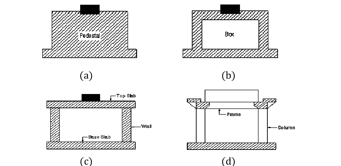
Figure 6.3.4 Types of machine foundations: (a) Block type; (b) Box type; (c) Wall type; (d) Framed type
3.20.2.2 Design considerations
For satisfactory performance, machine foundations should satisfy the following requirements: (i) resonance is avoided, (ii) bearing capacity and settlement are safe, and (iii) there is an adequate vibration and shock isolation. Avoidance of resonance is discussed in this Section. Resonance: Based on their operating frequencies, the machines are classified as (i) low speed having frequency less than 300 revolutions per minute (rpm), (ii) medium speed, frequency 300 to 1000 rpm, and (iii) high speed, frequency greater than 1000 rpm. To avoid resonance, the natural frequency (or the resonant frequency) of the machine foundation-soil system must be either very large or very small compared to the operating speed of the machine. Low speed machines ( < 300 rpm): Provide a foundation with a natural frequency at least twice the operating frequency, i.e., the frequency ratio () is less than 0.5. Natural frequency can be increased (i) by increasing base area or reducing total static weight of the foundation, (ii) by increasing modulus of shear rigidity of the soil by compaction, grouting or injection, (iii) by using piles to provide the required foundation stiffness. High speed machines ( > 1000 rpm): Provide a foundation with natural frequency not higher than one-half of the operating value, i.e., frequency ratio . Natural frequency can be decreased by increasing weight of foundation. During starting and stopping, the machine will operate briefly at resonant frequency of the foundation. Probable amplitude is computed at both and and compared with allowable values to determine if the foundation arrangement must be altered. Types of foundations: Considering their structural forms, the machine foundations, in general, are of the following types: (i) box foundation consisting of a pedestal of concrete, (ii) box foundation consisting of a hollow concrete block, (iii) wall foundation consisting of a pair of walls supporting the machine. (iv) framed foundation consisting of vertical columns and a top horizontal frame work which forms the seat of essential machinery. Low speed machines (e.g., forge hammers, presses, low speed reciprocating engines and compressors) are generally supported on block foundation having a large contact area with soil. Medium speed machines (e.g., reciprocating diesel and gas engines) also have, in general, block foundations resting on springs or suitable elastic pads. High speed and rotating type of machines (e.g., internal combustion engines, electric motors, and turbo generator machines) are generally mounted on framed foundations. Other high speed machines are placed on block foundations. As far as possible, the centre of gravity of the whole system and the centroid of the base area should be on the same vertical axis. At the most an eccentricity of 5% could be allowed. Permissible amplitude: Many times the permissible amplitude at operating speed is specified by the manufactures. If not specified, the following values may be adopted for guidance (i) low speed machines. (B1 < 500 rpm), horizontal and vertical vibrations, A 5 0.25 mm. (ii) operating speed B1 5 500 to 1500 rpm, A 5 0.4 mm to 0.6 mm for horizontal, and A 5 0.7 mm to 0.9 mm for vertical mode of vibration; (iii) operating speed B1 up to 3000 rpm, A 5 0.2 mm for horizontal and A 5 0.5 mm for vertical vibrations (iv) hammer foundations, A 5 10 mm.3.20.2.3 Design methods
The various design methods can be grouped as follows: (i) empirical and semiempirical methods, (ii) methods considering soil as a spring and (iii) methods considering soil as a semi-infinite elastic mass (elastic half-space-approach) and its equivalent lumped parameter method. The lumped parameter method is currently preferred and will be described here. A good machine foundation should satisfy the following criteria.- (i) Like ordinary foundations, it should be safe against shear failure caused by superimposed loads, and also the settlements should be within the safe limits.
- (ii) The soil pressure should normally not exceed 80% of the allowable pressure for static loading.
- (iii) There should be no possibility of resonance. The natural frequency of the foundation should be either greater than or smaller than the operating frequency of the machine.
- (iv) The amplitudes under service condition should be within the permissible limits for the machine.
- (v) The combined centre of gravity of the machine and the foundation should be on the vertical line passing through the centre of gravity of the base plane.
- (vi) Machine foundation should be taken to a level lower than the level of the foundation of the, adjacent buildings and should be properly separated.
- (vii) The vibrations induced should neither be annoying to the persons nor detrimental to other structures.
- (viii) Richart (1962) developed a plot for vertical vibrations, which is generally taken as a guide for various limits of frequency and amplitude which has been presented in Figure 6.3.5(a). A modified chart suggested by IS: 2974-Part 1, Figure 6.3.5(b) may also be used.
- (ix) The depth of the ground-water table should be at least one fourth of the width of the foundation below the base place.
3.20.2.4 Vibration analysis of a machine foundation:
Although a machine foundation has 6 degree of freedom, it is assumed to have a single degree of freedom for a simplified analysis. Figure 6.3.6 shows a machine foundation supported on a soil mass. In this case, the mass mf lumps together the mass of the machine and the mass of foundation. The total mass mf acts at the centre of gravity of the system. The mass is under the supporting action of the soil. The elastic action can be lumped together into a single elastic spring with a stiffness k. Likewise; all the resistance to motion is lumped into the damping coefficient c. Thus the machine foundation reduces to a single mass having one degree of freedom. The analysis of damped, forced vibration is, therefore, applicable to the machine foundation.
Figure 6.3.5 Limits of frequency and amplitudes of foundation: (a) Richart (1962) chart; (b) IS: 2974-Part 1, 1982
Figure 6.3.6 Machine foundation supported on a soil mass
3.20.2.5 Determination of parameters for vibration analysis
For vibration analysis of a machine foundation, the parameters m, c and k are required. These parameters can be determined as under. Mass (m): When a machine vibrates, some portion of the supporting soil mass also vibrates. The vibrating soil is known as the participating mass or in-phase soil mass. Therefore, the total mass of the system is equal to the mass of the foundation block and machine and the mass of the participating soil. Thus Unfortunately, there is no rational method to determine the magnitude of . It is usually related to the mass of the soil in the pressure bulb. The value of generally varies between zero and . In other words, the total mass varies between and in most cases. Spring Stiffness (k): The spring stiffness depends upon the type of soil, embedment of the foundation block, the contact area and the contact pressure distribution. The following are the common methods. Laboratory Test: A triaxial test with vertical vibrations is conducted to determine Young’s modulus . Alternatively, the modulus of rigidity is determined conducting the test under torsional vibration, and is obtained indirectly from the relation, , where µ is Poisson’s ratio. The stiffness is determined as Where, = cross-sectional area of the specimen, and = length of the specimen. The stiffness can also be obtained from the value of using the following relation given by Barken. Where, = base area of the machine, i.e. area of contact. A repeated plate load test is conducted and the stiffness of the soil is found as the slope of the load-deformation curve. The spring constant of the foundation is as under. For cohesive soils: For cohesionless soil: Where, is the width of foundation (in m), is the width of plate (in m). Alternatively, spring constant can be obtained from the subgrade modulus , as Where, = area of foundation. The resonance frequency is obtained using a vibrator of mass m set up on a steel plate supported on the ground. The spring stiffness obtained from the relation Where, is natural circular frequency. Damping is due to dissipation of vibration energy, which occurs mainly because of the following reasons.- (i) Internal friction loss due to hysteresis and viscous effects.
- (ii) Radiational loss due to propagation of waves through soil.
3.21 Geo-Hazard Analysis for Buildings
Geo-hazard analysis of buildings include design considerations for possible landslides, ground subsidence, earthquakes and other seismic events, erosion and scour, construction in toxic and/or contaminated landfills, groundwater contamination etc. A preliminary review of the selected site should be carried out for existence of any of the above mentioned geo-hazard in the area. A detailed analysis may be carried out only if the preliminary review indicates a significant threat for the building which may exist from any of the above mentioned potential geo-hazard at the selected location for the building. See relevant section for details.3.22 List of Related Appendices
Appendix D Methods of Soil Exploration, Sampling and Groundwater Measurements Appendix E Recommended Criteria for Identification and Classification of Expansive Soil- Appendix F Construction of Pile Foundation