
6.1 Analysis and Design - General Considerations
6.1.1 Definitions
The following terms are defined for general use in this Code. Specialized definitions appear in individual chapters. COLUMN Member with a ratio of height- to least lateral dimension exceeding 3 used primarily to support axial compression load. For a tapered member the least lateral dimension is the average of the top and bottom dimensions of the smaller side. COMPRESSION A cross section in which the net tensile strain in the CONTROLLED extreme tension steel at nominal strength is less than or SECTIONS equal to the compression-controlled strain limit. COMPRESSION The net tensile strain at balanced strain condition. See Sec CONTROLLED 6.3.3.3. STRAIN LIMIT CONCRETE Mixture of Portland cement or any other hydraulic cement, fine aggregate, coarse aggregate and water with or without admixture. CONCRETE, Concrete containing lightweight aggregate and an LIGHTWEIGHT equilibrium density as determined by ASTM C567, between 1450 - 1850 kg/m3 . CONCRETE, Concrete containing only aggregate that conforms to NORMALWEIGHT ASTM C33. CONCRETE, Compressive strength of concrete used in design and SPECIFIED evaluated in accordance with provisions of Sec 5.12, COMPRESSIVE expressed in N/mm2 . STRENGTH OF ′ CONNECTION A region that joins two or more members. CONTRACTION Formed, sawed, or tooled groove in a concrete structure JOINT to create a weakened plane and regulate the location of Formed, sawed, or tooled groove in a concrete structure to create a weakened plane and regulate the location of cracking resulting from the dimensional change of different parts of the structure.6.1.2 Notation and Symbols
Unless otherwise explicitly stated, the following units shall be implicit for the corresponding quantities in the design and other expressions provided in this Chapter:- = Depth of equivalent rectangular stress block as defined in Sec 6.3.2.7.1; (mm)
- = Shear span, equal to distance from center of concentrated load to either: (a) face of support for continuous or cantilevered members, or (b) center of support for simply supported members, mm, Sec 6.4 and Appendix I
- = Area of an individual bar or wire, mm2 , Sec 8.2
- = Net bearing area of the head of stud, anchor bolt, or headed deformed bar, mm2 , Sections 8.2.17 and K.5.3
- = Cross-sectional area of concrete section resisting shear transfer, mm2 , Sec 6.4.5.5
- = Cross-sectional area of a structural member measured to the outside edges of transverse reinforcement, mm2 ,Sections 6.3.9, 8.3.5.4
- = Area enclosed by outside perimeter of concrete cross section, mm2 , see Sections 6.4.4 and 8.3.8.3
- = Cross-sectional area at one end of a strut in a strut-and-tie model, taken perpendicular to the axis of the strut, mm2 , Sec I.3.1 Appendix I.
- = Gross area of concrete section bounded by web thickness and length of section in the direction of shear force considered, mm2 , Sec 8.3.6.2
- = Area of concrete section of an individual pier, horizontal wall segment, or coupling beam resisting shear, mm2 , Sec 8.3.6
- = Area of reinforcement in bracket or corbel resisting factored moment, mm2 , see Sec 6.4.7
- = Gross area of concrete section, mm2 For a hollow section, is the area of the concrete only and does not include the area of the void(s), see Sections 6.2, 6.3, 6.4, 6.6, 6.7, 6.10, 8.3.5
- = Total area of shear reinforcement parallel to primary tension reinforcement in a corbel or bracket, mm2 , see Sec 6.4.7
- = Effective cross-sectional area within a joint in a plane parallel to plane of reinforcement generating shear in the joint, mm2 , see Sec 8.3.7
- = Total area of longitudinal reinforcement to resist torsion, mm2 , Sec 6.4
- = Minimum area of longitudinal reinforcement to resist torsion, mm2 , see Sec 6.4.4.5.3
- = Area of reinforcement in bracket or corbel resisting tensile force , mm2 , see Sec 6.4.7
- = Area of a face of a nodal zone or a section through a nodal zone, mm2 , Sec I.5 Appendix I
- = Projected concrete failure area of a single anchor or group of anchors, for calculation of strength in tension, mm2 , see Sec K.5.2.1, Appendix K
- = Projected concrete failure area of a single anchor, for calculation of strength in tension if not limited by edge distance or spacing, mm2 , see Sec K.5.2.1, Appendix K
- = Gross area enclosed by shear flow path, mm2 , Sec 6.4
- = Area enclosed by centerline of outermost closed transverse torsional reinforcement, mm2 , Sec 6.4
- = Area of nonprestressed longitudinal tension reinforcement, mm2 , Sections 6.3, 6.4, 6.6, 6.8,
- = Area of tension reinforcement corresponding to moment of resistance , see Sec 6.3.15.1(b)
- = Area of additional tension steel, see Sec 6.3.15.1(b)
- = Area of compression reinforcement, mm2 , Sec I.3.5 Appendix I
- = Area of primary tension reinforcement in a corbel or bracket, mm2 , see Sec 6.4.7.3.5
- = Effective cross-sectional area of anchor in tension, mm2 , Sec K.5.1 Appendix K
- = Effective cross-sectional area of anchor in shear, mm2 , Sec K. 6.1 Appendix K
- = Area of reinforcement required to balance the longitudinal compressive force in the overhanging portion of the flange of a T- beam, see Sec 6.3.15.2(b)
- = Total cross-sectional area of transverse reinforcement (including crossties) within spacing and perpendicular to dimension , mm2 , Sec 8.3.5
- = Total area of surface reinforcement at spacing in the -th layer crossing a strut, with reinforcement at an angle to the axis of the strut, mm2 , Sec I.3.3 Appendix I
- = Minimum area of flexural reinforcement, mm2 , see Sec 6.3.5
- = Total area of nonprestressed longitudinal reinforcement (bars or steel shapes), mm2 , Sec 6.3.3
- = Area of structural steel shape, pipe, or tubing in a composite section, mm2 , Sec 6.3
- = Area of one leg of a closed stirrup resisting torsion within spacing , mm2 , Sec 6.4
- = Total cross-sectional area of all transverse reinforcement within spacing that crosses the potential plane of splitting through the reinforcement being developed, mm2 , Sec 8.2.3
- = Area of nonprestressed reinforcement in a tie, mm2 , Sec I.4.1 Appendix I
- = Area of shear reinforcement spacing , mm2 , Sections 6.4, 6.12
- = Projected concrete failure area of a single anchor or group of anchors, for calculation of strength in shear, mm2 , see Sec K.6.2.1 Appendix K
- = Projected concrete failure area of a single anchor, for calculation of strength in shear, if not limited by corner influences, spacing, or member thickness, mm2 , see Sec K.6.2.1 Appendix K
- = Maximum distance from center of anchor shaft to the edge of concrete, mm, Sec K.5.2.3 Appendix K
- = Minimum distance from center of anchor shaft to the edge of concrete, mm, Sec K.8.6 Appendix K
- = Distance from the center of an anchor shaft to the edge of concrete in one direction, mm. If shear is applied to anchor, is taken in the direction of the applied shear. If tension is applied to the anchor, is the minimum edge distance, Sec K.5.2 Appendix K
- = Distance from center of an anchor shaft to the edge of concrete in the direction perpendicular to , mm, Sec K.5.4 Appendix K
- = Smaller of: (a) the distance from center of a bar or wire to nearest concrete surface, and (b) one-half the center-to-center spacing of bars or wires being developed, mm, Sec 8.2.3
- =Clear cover of reinforcement, mm, see Sec 6.3.6.4
- = Dimension of rectangular or equivalent rectangular column, capital, or bracket measured in the direction of the span for which moments are being determined, mm, Sections 6.4, 6.5, 8.3.4
- = Dimension of rectangular or equivalent rectangular column, capital, or bracket measured in the direction perpendicular to , mm, Sec 6.5
- = Cross-sectional constant to define torsional properties of slab and beam, see Sec 6.5.6.4.2
- = Factor relating actual moment diagram to an equivalent uniform moment diagram, Sec 6.3
- = Distance from extreme compression fiber to centroid of longitudinal tension reinforcement, mm, Sections 6.2, 6.3, 6.4, 6.6, 6.12, 8.1.5, 8.2.7, 8.3.4
- = Distance from extreme compression fiber to centroid of longitudinal compression reinforcement, mm, Sec 6.2
- = Outside diameter of anchor or shaft diameter of headed stud, headed bolt, or hooked bolt, mm, see Sec K.8.4, Appendix K
- = Value substituted for when an oversized anchor is used, mm, see Sec K.8.4, Appendix K
- = Diameter of pile at footing base, mm, Sec 6.8
- = Distance from extreme compression fiber to centroid of extreme layer of longitudinal tension steel, mm, Sections 6.2, 6.3
- = Dead loads, or related internal moments and forces, Sections 6.1, 6.2, 6.11
- = Distance from the inner surface of the shaft of a J- or L-bolt to the outer tip of the J- or L-bolt, mm, Sec K.5.3 Appendix K
- = Distance between resultant tension load on a group of anchors loaded in tension and the Centroid of the group of anchors loaded in tension, mm; is always positive, Sec K.5.2 Appendix K
- = Distance between resultant shear load on a group of anchors loaded in shear in the same direction, and the centroid of the group of anchors loaded in shear in the same direction, mm; is always positive, Sec K.6.2 Appendix K
- = Load effects of earthquake, or related internal moments and forces, Sections 6.2, 8.3.6
- = Modulus of elasticity of concrete, MPa see Sec 6.1.7.1, 6.2, 6.3, 6.6, 6.9
- = Modulus of elasticity of beam concrete, MPa, Sec 6.5
- = Modulus of elasticity of slab concrete, MPa, Sec 6.5
- = Flexural stiffness of compression member,N⋅mm2, see Sec 6.3.10.6
- = Modulus of elasticity of reinforcement and structural steel, MPa, see Sections 6.1.7.2, 6.3, 6.6
- = Specified compressive strength of concrete, MPa, Sections 6.1 to 6.4, 6.6, 6.9, 8.2, 8.3, Appendices I, K
- = Effective compressive strength of the concrete in a strut or a nodal zone, MPa, Sec 6.8.5, I.3.1 Appendix I
- = Average splitting tensile strength of lightweight concrete, MPa, See Sec 6.1.8.1 Sections 6.1, 6.4, 8.2.3.4
- = Stress due to unfactored dead load, at extreme fiber of section where tensile stress is caused by externally applied loads, MPa, Sec 6.4
- = Compressive stress in concrete at centroid of cross section resisting externally applied loads or at junction of web and flange when the centroid lies within the flange, MPa. (In a composite member, is the resultant compressive stress at centroid of composite section, or at junction of web and flange when the centroid lies within the flange, due to both prestress and moments resisted by precast member acting alone), Sec 6.4
- = Modulus of rupture of concrete, MPa, see Sections 6.2.5, 6.6
- = Calculated tensile stress in reinforcement at service loads, MPa, Sec 6.3
- = Stress in compression reinforcement under factored loads, MPa, Sec I.3.5 Appendix I
- = Specified tensile strength of anchor steel, MPa, Appendix K
- = Specified yield strength of reinforcement, MPa, Sections 6.2 to 6.4, 6.6, 6.9, 6.12, 8.1 to 8.3, I.4.1
- = Specified yield strength of anchor steel, MPa, Sec K.4.4 Appendix K
- = Specified yield strength of transverse reinforcement, MPa, Sections 6.3, 6.4, 8.3.3.4
- = Loads due to weight and pressures of fluids with well-defined densities and controllable maximum heights, or related internal moments and forces, Sec 6.2
- = Nominal strength of a strut, tie, or nodal zone, N, Sec I.2.6 Appendix I
- = Nominal strength at face of a nodal zone, N, Sec I.5.1 Appendix I
- = Nominal strength of a strut, N, Sec I.3.1 Appendix I
- = Nominal strength of a tie, N, Sec I.4.1 Appendix I
- = Factored force acting in a strut, tie, bearing area, or nodal zone in a strut-and-tie model, N, Sec I.2.6 Appendix I
- = Overall thickness or height of member, mm, Sections 6.2 to 6.4, 6.6, 6.11, 6.12, 8.1.6, 8.3.4, I.1
- = Thickness of member in which an anchor is located, measured parallel to anchor axis, mm, Sec K.6.2 Appendix K
- = Cross-sectional dimension of member core measured to the outside edges of the transverse reinforcement composing area ,mm, Sec 8.3.5
- = Effective embedment depth of anchor, mm, see Sec K.5.2, Appendix K
- = Thickness of overhanging portion of the flange of a T-beam, Sec 6.3.15.2(b)
- = Depth of shear head cross section, mm, Sec 6.4
- = Height of entire wall from base to top or height of the segment of wall considered, mm, Sections 6.4, 8.3.6
- = Maximum center-to-center horizontal spacing of crossties or hoop legs on all faces of the column, mm, Sec 8.3.5
- = Loads due to weight and pressure of soil, water in soil, or other materials, or related internal moments and forces, Sec 6.2
- = Moment of inertia of section about centroidal axis, mm4 , Sections 6.3, 6.4
- = Moment of inertia of gross section of beam about centroidal axis, mm4 , Sec 6.5.6
- = Moment of inertia of cracked section transformed to concrete, mm4 , Sec 6.2
- = Effective moment of inertia for computation of deflection, mm4 , Sec 6.2.5
- = Moment of inertia of gross concrete section about centroidal axis, neglecting reinforcement, mm4 , Sections 6.2, 6.3, 6.6
- = Moment of inertia of gross section of slab about centroidal axis defined for calculating and , mm4 , Sec 6.5
- = Moment of inertia of reinforcement about centroidal axis of member cross section, mm4 , Sec 6.3
- = Moment of inertia of structural steel shape, pipe, or tubing about centroidal axis of composite member cross section, mm4 , Sec 6.3
- = Effective length factor for compression members, Sections 6.3, 6.6
- = Coefficient for basic concrete breakout strength in tension, Sec K.5.2 Appendix K
- = Coefficient for pryout strength, Sec K.6.3 Appendix K
- = Transverse reinforcement index, Sec 8.2.3.3
- = Span length of beam or one-way slab; clear projection of cantilever, mm, Sec 6.2
- = Additional embedment length beyond centerline of support or point of inflection, mm, Sec 8.2.8
- = Length of clear span in short direction, Sec 6.5.8
- = Length of clear span in long direction, Sec 6.5.8
- = Length of compression member in a frame, measured center-tocenter of the joints in the frame, mm, Sections 6.3, 6.6
- = Development length in tension of deformed bar, deformed wire, plain and deformed welded wire reinforcement, or mm, Sections 6.9, 8.2.3, 8.3.6
- = Development length in compression of deformed bars and deformed wire, mm, Sec 8.2.4
- = Development length in tension of deformed bar or deformed wire with a standard hook, measured from critical section to outside end of hook (straight embedment length between critical section and start of hook [point of tangency] plus inside radius of bend and one bar diameter), mm, see Sections 8.2.6, 8.3.6
- = Development length in tension of headed deformed bar, measured from the critical section to the bearing face of the head, mm, Sections 8.2.17, 8.3.6
- = Load bearing length of anchor for shear, mm, Sec K.6.2.2, Appendix K
- = Length of clear span measured face-to-face of supports, mm, Sections 6.1 to 6.5, 6.10, 8.2.9, 8.3.4
- = Length, measured from joint face along axis of structural member, over which special transverse reinforcement must be provided, mm, Sec 8.3.5
- = Span of member under load test, taken as the shorter span for twoway slab systems, mm. Span is the smaller of: (a) distance between centers of supports, and (b) clear distance between supports plus thickness ℎ of member. Span for a cantilever shall be taken as twice the distance from face of support to cantilever end, Sec 6.11
- = Unsupported length of compression member, mm, Sec 6.3.10
- = Additional nominal flexural strength at section due to added compression steel and additional tension steel , Sec 6.3.15.1, and moment of resistance developed by the web of a T-beam, Sec 6.3.15.2
- = Total factored static moment, N⋅mm, Sec 6.5
- = Required plastic moment strength of shear head cross section, N⋅mm, Sec 6.4
- = Probable flexural strength of members, with or without axial load, determined using the properties of the member at the joint faces assuming a tensile stress in the longitudinal bars of at least and a strength reduction factor, , of 1.0, N⋅mm, Sec 8.3.8
- = Factored moment due to loads causing appreciable sway, N⋅mm, Sec 6.3
- = Factored moment at section, N⋅mm, Sections 6.3, 6.4, 6.5, 6.6, 8.3.6
- = Moment at mid height of wall due to factored lateral and eccentric vertical loads, not including effects, N⋅mm, Sec 6.6
- = Moment resistance contributed by shear head reinforcement, N⋅mm, Sec 6.4
- = Smaller factored end moment on a compression member, to be taken as positive if member is bent in single curvature, and negative if bent in double curvature, N⋅mm, Sec 6.3
- = Factored end moment on a compression member at the end at which acts, due to loads that cause no appreciable side sway, calculated using a first-order elastic frame analysis, N⋅mm, Sec 6.3
- = Factored end moment on compression member at the end at which acts, due to loads that cause appreciable side sway, calculated using a first-order elastic frame analysis, N⋅mm, Sec 6.3
- = Larger factored end moment on compression member. If transverse loading occurs between supports, is taken as the largest moment occurring in member. Value of is always positive, N⋅mm, Sec 6.3
- = Minimum value of , N⋅mm, Sec 6.3
- = Factored end moment on compression member at the end at which acts, due to loads that cause no appreciable side sway, calculated using a first-order elastic frame analysis, N⋅mm, Sec 6.3
- = Factored end moment on compression member at the end at which acts, due to loads that cause appreciable sidesway, calculated using a first-order elastic frame analysis, N⋅mm, Sec 6.3
- = Number of items, such as strength tests, bars, wires, monostrand anchorage devices, anchors, or shear head arms, Sec 6.4, 8.2, K.1 Width of flight, Figure 6.6.29.
- = Basic concrete breakout strength in tension of a single anchor in cracked concrete, N, Sec K.5.2.2
- = Nominal concrete breakout strength in tension of a single anchor, N, see Sec K.5.2.1
- = Nominal concrete breakout strength in tension of a group of anchors, N, Sec K.5.2.1
- = Nominal strength in tension, N, Sec K.3.3
- = Pullout strength in tension of a single anchor in cracked concrete, N, Sections K.2.3 K.3.3, K.5.3
- = Nominal pullout strength in tension of a single anchor, N, Sections K.4.1, K.5.3
- = Nominal strength of a single anchor or group of anchors in tension as governed by the steel strength, N, Sections K.4.1, K.5.1
- = Side-face blowout strength of a single anchor, N, Sec K.4.1
- = Side-face blowout strength of a group of anchors, N, Sections K.4.1, K.5.4
- = Factored axial force normal to cross section occurring simultaneously with or ; to be taken as positive for compression and negative for tension, N, Sec 6.4
- = Factored tensile force applied to anchor or group of anchors, N, Sections K.4.1, K.7
- = Factored horizontal tensile force applied at top of bracket or corbel acting simultaneously with , to be taken as positive for tension, N, Sec 6.4
- = Outside perimeter of concrete cross section, mm, Sec 6.4.4.1
- = Perimeter of centerline of outermost closed transverse torsional reinforcement, mm, Sec 6.4
- = Nominal torsional moment strength, N⋅mm, Sec 6.4
- = Factored torsional moment at section, N⋅mm, Sec 6.4
- = Required strength to resist factored loads or related internal moments and forces, Sec 6.2
- = Nominal shear stress, MPa, Sections 6.4, 8.3.8
- = Basic concrete breakout strength in shear of a single anchor in cracked concrete, N, Sec K.6.2
- = Nominal shear strength provided by concrete, N, Sections 6.1, 6.4, 6.5, 8.3.8
- = Nominal concrete breakout strength in shear of a single anchor, N, Sections K.4.1, K.6.2
- = Nominal concrete breakout strength in shear of a group of anchors, N, Sections K.4.1, K.6.2
- = Nominal shear strength provided by concrete when diagonal cracking results from combined shear and moment, N, Sec 6.4
- = Nominal concrete pryout strength of a single anchor, N, Sec K.6.3.1
- = Nominal concrete pryout strength of a group of anchors, N, Sec K.6.3.1
- = Nominal shear strength provided by concrete when diagonal cracking results from high principal tensile stress in web, N, Sec 6.4
- = Shear force at section due to unfactored dead load, N, Sec 6.4
- = Design shear force corresponding to the development of the probable moment strength of the member, N, Sec 8.3.8
- = Nominal shear strength, N, Sections 6.1, 6.3, 6.4, 8.3.6, K.3.3
- = Nominal horizontal shear strength, N, Sec 6.12
- = Nominal shear strength provided by shear reinforcement, N, Sec 6.4
- = Nominal strength in shear of a single anchor or group of anchors as governed by the steel strength, N, see Sections K.3.3, K.6.1.1, K.6.1.2
- = Factored shear force at section, N, Sections 6.4, 6.5, 6.12, 8.2.7, 8.3.6
- = Factored shear force applied to a single anchor or group of anchors, N, K.4.1
- = Factored shear force on critical section of two-way slab action due to gravity loads, N, Sec 8.3.12
- = Factored horizontal shear in a story, N, Sec 6.3
- = Uniform load, Sec 6.5.8
- = Density (unit weight) of normal weight concrete or equilibrium density of light weight concrete, kg/m3 , Sections 6.1, 6.2
- = Factored load per unit length of beam or one way slab, Sec 6.1
- = Wind load, or related internal moments and forces, Sec 6.2
- = Shorter overall dimension of rectangular part of cross section, mm, Sec 6.5
- = Longer overall dimension of rectangular part of cross section, mm, Sec 6.5
- = Distance from centroidal axis of gross section, neglecting reinforcement, to tension face, mm, Sections 6.2, 6.4
- = Angle defining the orientation of reinforcement, Sections 6.4, I.3.3
- = Coefficient defining the relative contribution of concrete strength to nominal wall shear strength, Sec 8.3.6
- = Ratio of flexural stiffness of beam section to flexural stiffness of a width of slab bounded laterally by centerlines of adjacent panels (if any) on each side of the beam, Sections 6.2, 6.4.2, 6.5.6, 6.5.8
- = Average value of for all beams on edges of a panel, Sec 6.2
- = in direction of , Sec 6.5
- = in direction of , Sec 6.5
- = Angle between the axis of a strut and the bars in the i-th layer of reinforcement crossing that strut, Sec I.3.3
- = Constant used to compute in slabs and footings, Sec 6.4
- = Ratio of flexural stiffness of shear head arm to that of the surrounding composite slab section, Sec 6.4.10
- = Ratio of long to short dimensions: clear spans for two-way slabs, Sec 6.2.5 sides of column, concentrated load or reaction area, Sec 6.4.10; or sides of a footing, Sections 6.2, 6.4, 6.8.4
- = Ratio of area of reinforcement cut off to total area of tension reinforcement at section, Sec 8.2.7
- = Ratio used to account for reduction of stiffness of columns due to sustained axial loads, Sec 6.3.10
- = Ratio used to account for reduction of stiffness of columns due to sustained lateral loads, Sec 6.3.10.4
- = Factor to account for the effect of the anchorage of ties on the effective compressive strength of a nodal zone, Sec I.5.2
- = Factor to account for the effect of cracking and confining reinforcement on the effective compressive strength of the concrete in a strut, Sec I.3.2
- = Ratio of torsional stiffness of edge beam section to flexural stiffness of a width of slab equal to span length of beam, center-to-center of supports, Sec 6.5.6.4
- = Factor relating depth of equivalent rectangular compressive stress block to neutral axis depth, Sec 6.3.2.7
- = Factor used to determine the unbalanced moment transferred by flexure at slab-column connections, Sections 6.4, 6.5.5.3
- = Factor used to determine portion of reinforcement located in center band of footing, Sec 6.8.4.4
- = Factor used to determine the unbalanced moment transferred by eccentricity of shear at slab-column connections, Sec 6.4.10.7
- = Moment magnification factor to reflect effects of member curvature between ends of compression member, Sec 6.3
- = Moment magnification factor for frames not braced against side sway, to reflect lateral drift resulting from lateral and gravity loads, Sec 6.3
- = Design displacement, mm, Sec 8.3.6
- = Computed, out-of-plane deflection at mid height of wall corresponding to cracking moment, , mm, Sec 6.6
- = Computed, out-of-plane deflection at mid height of wall corresponding to nominal flexural strength, , mm, Sec 6.6
- = Relative lateral deflection between the top and bottom of a story due to lateral forces computed using a first-order elastic frame analysis and stiffness values satisfying Sec 6.3
- = Difference between initial and final (after load removal) deflections for load test or repeat load test, mm, Sec 6.11
- = Computed, out-of-plane deflection at mid height of wall due to service loads, mm, Sec 6.6
- = Computed deflection at mid height of wall due to factored loads, mm, Sec 6.6
- = Measured maximum deflection during first load test, mm, Sec 6.11.5.2
- = Maximum deflection measured during second load test relative to the position of the structure at the beginning of second load test, mm, Sec 6.11.5.2
- = Net tensile strain in extreme layer of longitudinal tension steel at nominal strength, creep, shrinkage, and temperature, Sections 6.1 to 6.3
- = Angle between axis of strut, compression diagonal, or compression field and the tension chord of the member, Sec 6.4.4
- = Modification factor reflecting the reduced mechanical properties of lightweight concrete, all relative to normal weight concrete of the same compressive strength, Sections 6.1.8.1, 6.2, 6.4.5.4, 6.9, 8.2.3.4, 8.2.6.2, 8.2.10.2, 8.3.6, I.3.2, K.5.2
- = Multiplier for additional deflection due to long-term effects, Sec 6.2.5.2.5
- = Coefficient of friction, Sec 6.4.5.4.3
- = Time-dependent factor for sustained load, Sec 6.2.5.2
- = Ratio of to , Sections 6.4, 6.5, 8.3.4
- = Ratio of to , Sections 6.2, 6.3.15.1
- = Ratio of to producing balanced strain conditions, Sections 6.3.3.2, 6.5, 6.6
- = Ratio of to , Sec 6.3.15.2
- = Ratio of area of distributed longitudinal reinforcement to gross concrete area perpendicular to that reinforcement, Sections 6.4, 6.6, 8.3.6
- = Maximum reinforcement ratio allowed for beams corresponding to = 0.004, Sec 6.3.15.1
6.1.3 General
6.1.3.1
Members shall be designed for adequate strength in accordance with the provisions of this Chapter, using load factors specified in Sec 2.7.3.1 and strength reduction factors in Sec 6.2.3.1.6.1.3.2
Design of reinforced concrete members using Working Stress Design method (Appendix J) is also permitted.6.1.3.3
Structures and structural members shall be designed to have design strength at all sections at least equal to the required strength (U) calculated for the factored loads and forces in such combinations as are stipulated in Chapter 2, Loads. The nominal strength provided for the section multiplied by the strength reduction factor shall be equal to or greater than the calculated required strength U.6.1.3.4
Members shall also meet all the other requirements of this Code to ensure adequate performance at service loads.6.1.3.5
Design strength of reinforcement represented by the values of and used in design calculations shall not exceed 550 MPa, and for transverse reinforcement in Sections 6.3.9.3 and 8.3. or may exceed 420 MPa, only if the ratio of the actual tensile strength to the actual yield strength is not less than 1.20, and the elongation percentage is not less than 16.6.1.3.6
For structural concrete, shall not be less than 17 MPa. No maximum value of shall apply unless restricted by a specific Code provision.6.1.4 Loading
6.1.4.1
Loads and their combinations shall be in accordance with the requirements specified in Chapter 2 of this Part.6.1.4.2
Structures shall be designed to resist all applicable loads.6.1.4.3
Effects of forces due to crane loads, vibration, impact, shrinkage, temperature changes, creep, expansion of shrinkage-compensating concrete, and unequal settlement of supports shall be duly considered.6.1.4 Methods of Analysis
6.1.4.1
Members of frames or continuous construction (beams or one-way slabs) shall be designed for the maximum effects of factored loads as determined by the theory of elastic analysis, except as modified for redistribution of moments in continuous flexural members according to Sec 6.1.5. Design is permitted to be simplified by using the assumptions specified in Sections 6.1.6, 6.1.9 to 6.1.12.6.1.4.2
Frame analysis by approximate methods shall be permitted for buildings of usual types of construction, spans, and story heights.6.1.4.3
Provided (a) to (e) below are satisfied, the approximate moments and shears given here shall be permitted for design of continuous beams and oneway slabs (slabs reinforced to resist flexural stresses in only one direction), as an alternate to frame analysis:- (a) There are two or more spans;
- (b) Spans are approximately equal, with the larger of two adjacent spans not greater than the shorter by more than 20 percent;
- (c) Loads are uniformly distributed;
- (d) Unfactored live load, , does not exceed three times unfactored dead load, ; and
- (e) Members are prismatic.
6.1.4.4
Strut-and-tie models, provided in Appendix I, shall be permitted to be used in the design of structural concrete.6.1.5 Redistribution of Moments in Continuous Flexural Members
6.1.5.1
It shall be permitted to decrease factored moments calculated by elastic theory at sections of maximum negative or maximum positive moment in any span of continuous flexural members for any assumed loading arrangement by not more than percent, with a maximum of 20 percent, except where approximate values for moments are used.6.1.5.2
Redistribution of moments shall be made only when is equal to or greater than 0.0075 at the section at which moment is reduced.6.1.5.3
At all other sections within the spans, the reduced moment shall be used for calculating redistributed moments. Static equilibrium shall have to be maintained after redistribution of moments for each loading arrangement.6.1.6 Span Length
6.1.6.1
The span length of a simply supported beam shall be taken as the smaller of the distance between the centres of bearings, or the clear distance between supports plus the effective depth.6.1.6.2
For determination of moments in analysis of frames or continuous construction, span length shall be taken as the distance center-to-center of supports.6.1.6.3
Design on the basis of moments at faces of support shall be permitted for beams built integrally with supports.6.1.6.4
It shall be permitted to analyze solid or ribbed slabs built integrally with supports, with clear spans not more than 3 m, as continuous slabs on knife edge supports with spans equal to the clear spans of the slab and width of beams otherwise neglected.6.1.6.5
The effective length of a cantilever is its length to the face of the support plus half its effective depth, except where it forms the end of a continuous beam, where the length to the centre of support shall be used.6.1.7 Modulus of Elasticity
6.1.7.1
Modulus of elasticity, , for concrete shall be permitted to be taken as , (in MPa) for values of between 1440 and 2560 kg/m3 . For normal weight concrete, shall be permitted to be taken as (in MPa).6.1.7.2
Modulus of elasticity, , for reinforcement shall be permitted to be taken as 200,000 MPa.6.1.8 Lightweight Concrete
6.1.8.1
To account for the use of lightweight concrete, unless specifically noted otherwise, a modification factor appears as a multiplier of in all applicable equations and sections of this Code, where, = 0.85 for sand-lightweight concrete and 0.75 for all-lightweight concrete. Linear interpolation between 0.75 and 0.85 shall be permitted, on the basis of volumetric fractions, when a portion of the lightweight fine aggregate is replaced with normal weight fine aggregate. Linear interpolation between 0.85 and 1.0 shall be permitted, on the basis of volumetric fractions, for concrete containing normal weight fine aggregate and a blend of lightweight and normal weight coarse aggregates. For normal weight concrete, = 1.0. If average splitting tensile strength of lightweight concrete, , is specified, .6.1.9 Stiffness
6.1.9.1
For computing relative flexural and torsional stiffnesses of columns, walls, floors, and roof systems, use of any set of reasonable assumptions shall be permitted. The assumptions adopted shall be consistent throughout analysis.6.1.9.2
Both in determining moments and in design of members, effect of haunches shall be considered.6.1.10 Effective Stiffness for Determining Lateral Deflections
6.1.10.1
Lateral deflections resulting from service lateral loads for reinforced concrete building systems shall be computed by either a linear analysis with member stiffness determined using 1.4 times the flexural stiffness defined in Sections 6.1.11.2 and 6.1.11.3 or by a more detailed analysis. Member properties shall not be taken greater than the gross section properties.6.1.10.2
Lateral deflections resulting from factored lateral loads for reinforced concrete building systems shall be computed either by linear analysis with member stiffness defined by (a) or (b), or by a more detailed analysis considering the reduced stiffness of all members under the loading conditions:- (a) By section properties defined in Sec 6.3.10.4.1(a) to (c); or
- (b) 50 percent of stiffness values based on gross section properties.
6.1.10.3
Lateral deflections resulting from factored lateral loads shall be permitted to be computed by using linear analysis, where two-way slabs without beams are designated as part of the seismic-force-resisting system. The stiffness of slab members shall be defined by a model that is in substantial agreement with results of comprehensive tests and analysis and the stiffness of other frame members shall be as defined in Sec 6.1.11.2.6.1.11 Considerations for Columns
6.1.11.1
Columns shall be designed to resist the axial forces from factored loads on all floors or roof and the maximum moment from factored loads on a single adjacent span of the floor or roof under consideration. Loading condition resulting the maximum ratio of moment to axial load shall also be considered.6.1.11.2
In frames or continuous construction, consideration shall be given to the effect of unbalanced floor or roof loads on both exterior and interior columns and of eccentric loading due to other causes.6.1.11.3
It shall be permitted to assume far ends of columns built integrally with the structure to be fixed, while computing gravity load moments in columns.6.1.11.4
Resistance to moments at any floor or roof level shall be provided by distributing the moment between columns immediately above and below the given floor in proportion to the relative column stiffnesses and conditions of restraint.6.1.12 Live Load Arrangement
6.1.12.1
The following shall be permitted to assume:- (a) The live load is applied only to the floor or roof under consideration; and
- (b) The far ends of columns built integrally with the structure are considered to be fixed.
6.1.12.2
Arrangement of live load shall be permitted to be assumed to be limited to combinations of:- (a) Factored dead load on all spans with full factored live load on two adjacent spans; and
- (b) Factored dead load on all spans with full factored live load on alternate spans.
6.1.13 Construction of T-beam
6.1.13.1
In the construction of T-beam, the flange and web shall be built integrally or otherwise effectively bonded together.6.1.13.2
Width of slab effective as a T-beam flange shall not exceed one-quarter of the span length of the beam, and the effective overhanging flange width on each side of the web shall not exceed:- (a) Eight times the slab thickness; and
- (b) One-half the clear distance to the next web.
6.1.13.3
The effective overhanging flange width for beams with a slab on one side only shall not exceed:- (a) One-twelfth the span length of the beam;
- (b) Six times the slab thickness; and
- (c) One-half the clear distance to the next web.
6.1.13.4
Isolated beams, in which the T-shape is used to provide a flange for additional compression area, shall have a flange thickness not less than one-half the width of web and an effective flange width not more than four times the width of web.6.1.13.5
When primary flexural reinforcement in a slab that is considered as a T-beam flange (excluding joist construction) is parallel to the beam, reinforcement shall be provided in the top of the slab in the direction perpendicular to the beam and in accordance with the following:6.1.13.5.1
Transverse reinforcement shall be designed to carry the factored load on the overhanging slab width assumed to act as a cantilever. For isolated beams, the full width of overhanging flange shall be considered. For other T- beams, only the effective overhanging slab width need be considered.6.1.13.5.2
Spacing of transverse reinforcement shall be not farther apart than five times the slab thickness, nor farther apart than 450 mm.6.1.14 Construction of Joist
6.1.14.1
Construction of joist consists of a monolithic combination of regularly spaced ribs and a top slab arranged to span in one direction or two orthogonal directions.6.1.14.2
Width of ribs shall not be less than 100 mm, and the ribs shall have a depth of not more than 3.5 times the minimum width of rib.6.1.14.3
Clear spacing between ribs shall not exceed 750 mm.6.1.14.4
Joist construction not meeting the limitations of Sections 6.1.15.1 to 6.1.15.3 shall be designed as slabs and beams.6.1.14.5
When permanent burned clay or concrete tile fillers of material having a unit compressive strength at least equal to r in the joists are used:6.1.14.5.1
For shear and negative moment strength computations, the vertical shells of fillers in contact with the ribs shall be permitted to include. Other portions of fillers shall not be included in strength computations.6.1.14.5.2
Slab thickness over permanent fillers shall be not less than 1/12th the clear distance between ribs, nor less than 40 mm.6.1.14.5.3
Reinforcement normal to the ribs shall be provided in the in oneway joists, as required by Sec 8.1.116.1.14.6
When removable forms or fillers are used, which do not comply with Sec 6.1.15.5, then:6.1.14.6.1
Slab thickness shall be not less than 1/12th the clear distance between ribs, nor less than 50 mm.6.1.14.6.2
Reinforcement normal to the ribs shall be provided in the slab as required for flexure, considering load concentrations, if any, but not less than required by Sec 8.1.116.1.14.7
Where conduits or pipes as permitted by relevant provisions of embedments in concrete are embedded within the slab, slab thickness shall be at least 25 mm greater than the total overall depth of the conduits or pipes at any point. Conduits or pipes shall not impair significantly the strength of the construction.6.1.14.8
For joist construction, \phi shall be permitted to be 10 percent more than that specified in Sec 6.4.6.1.15 Separate Floor Finish
6.1.15.1
Unless placed monolithically with the floor slab or designed in accordance with requirements of Sec. 6.12, floor finish shall not be included as part of a structural member.6.1.15.2
All concrete floor finishes shall be permitted to be considered as part of required cover or total thickness for nonstructural considerations.6.2 Strength and Serviceability Requirements
6.2.1 General
6.2.1.1
Structures and structural members shall be designed to have design strengths at all sections at least equal to the required strengths calculated for the factored loads and forces in such combinations as are stipulated in this Code.6.2.1.2
Members also shall meet all other requirements of this Code to ensure adequate performance at service load levels.6.2.2 Required Strength
6.2.2.1
Required strength shall be at least equal to the effects of factored loads in such combinations as are stipulated in Chapter 2, Loads.6.2.2.2
If resistance to impact effects is taken into account in design, such effects shall be included with .6.2.2.3
Estimations of differential settlement, creep, shrinkage, expansion of shrinkage-compensating concrete, or temperature change shall be based on a realistic assessment of such effects occurring in service.6.2.2.4
For structures like emergency preparedness centre, cyclone shelters etc. in coastal zone, in load combination 4 of Sec 2.7.3.1 of Chapter 2, the coefficient of live load L shall be taken 1.6 instead of 1.0.6.2.3 Design Strength
6.2.3.1
Design strength provided by a member, and its connections to other members, in terms of flexure, axial load, shear, and torsion, shall be taken as the nominal strength calculated in accordance with the requirements and assumptions of this Chapter, multiplied by a strength reduction factors as stipulated in Sections 6.2.3.2 to 6.2.3.4.6.2.3.2
Strength reduction factor is given in Sections 6.2.3.2.1 to 6.2.3.2.6:6.2.3.2.1
For tension-controlled sections as defined in Sec 6.3.3.4: 0.906.2.3.2.2
For compression-controlled sections, as defined in Sec 6.3.3.3: |Members with spiral reinforcement conforming to Sec 6.3.9.3:|0.75| |Other reinforced members:|0.65| For sections in which the net tensile strain in the extreme tension steel at nominal strength, , is between the limits for compression-controlled and tension-controlled sections, shall be permitted to be linearly increased from that for compression-controlled sections to 0.90 as increases from the compression controlled strain limit to 0.005 (Also see Figure 6.6.1). While interpolating, it shall be permitted to round to second digit after decimal.6.2.3.2.3
It shall be permitted for compression-controlled sections, as defined in Sec 6.3.3.3, the following optional, more conservative alternative values of strength reduction factor , where less controlled construction environment justifies such selection according to engineering judgment of the designer: For members with spiral reinforcement conforming to Sec 6.3.9.3:0.70 For other reinforced members: 0.60 For sections in which the net tensile strain in the extreme tension steel at nominal strength, , is between the limits for compression-controlled and tension-controlled sections, shall be permitted to be linearly increased from that for compression-controlled sections to 0.90 as increases from the compression controlled strain limit to 0.005 (Also see Figure 6.6.2). While interpolating, it shall be permitted to round to second digit after decimal.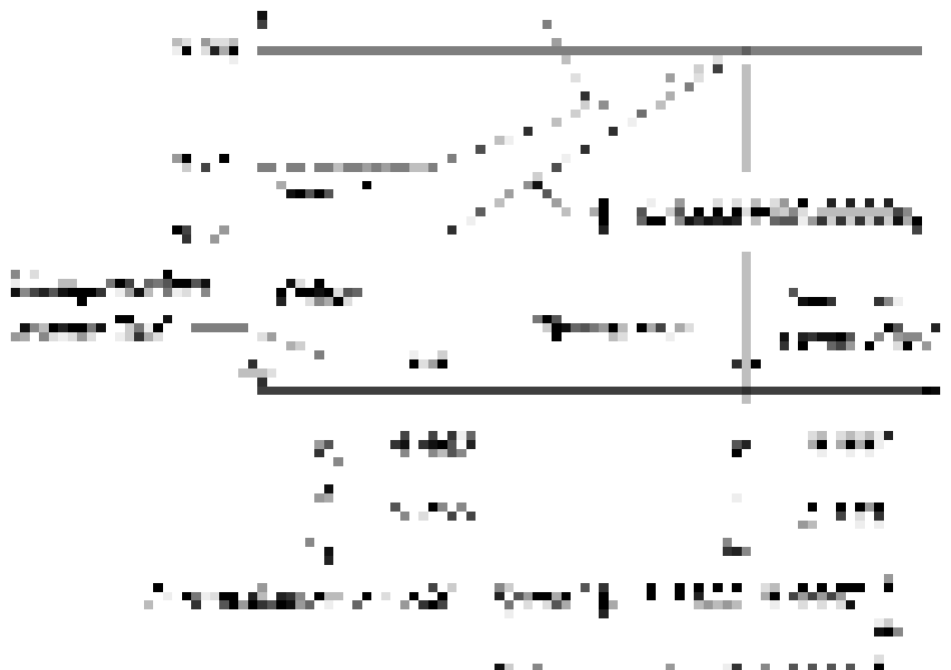
Figure 6.6.1 Variation of $\phi$ with net tensile strain in extreme tension steel, $\varepsilon_t$ and $c/d_t$ for Grade 420 reinforcement and for prestressing steel
6.2.3.2.4
Strength reduction factor for shear and torsion: 0.756.2.3.2.5
Strength reduction factor for bearing on concrete (except for posttensioned anchorage zones and strut-and-tie models): 0.656.2.3.2.6
Strength reduction factor for strut-and-tie models (Appendix I), and struts, ties, nodal zones, and bearing areas in such models: 0.756.2.3.2.7
Calculation of development length specified in Sec 8.2 does not require strength reduction factor .6.2.3.3
For structures relying on intermediate precast structural walls in Seismic Design Category D, special moment frames, or special structural walls to resist earthquake effects, , shall be modified as given in (a) through (c):- (a) For any structural member that is designed to resist , if the nominal shear strength of the member is less than the shear corresponding to the development of the nominal flexural strength of the member, for shear shall be 0.60. The nominal flexural strength shall be determined considering the most critical factored axial loads and including ;
- (b) For diaphragms, for shear shall not exceed the minimum for shear used for the vertical components of the primary seismic-forceresisting system;
- (c) For joints and diagonally reinforced coupling beams, for shear shall be 0.85.
6.2.3.4
Strength reduction factor shall be 0.60 for flexure, compression, shear, and bearing of structural plain concrete.6.2.4 Design Strength for Reinforcement
The values of and used in design calculations shall not exceed 550 MPa, except for transverse reinforcement in Sections 6.3.9.3 and 8.3.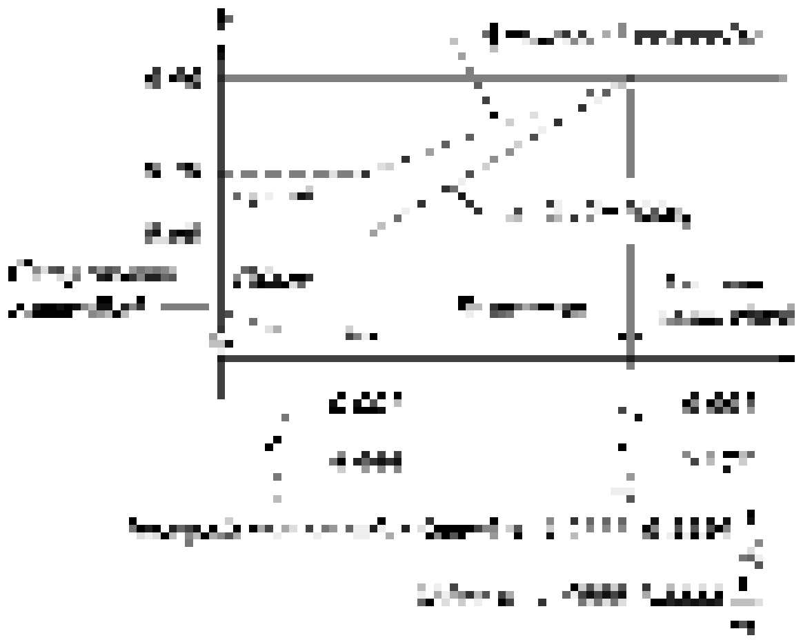
Figure 6.6.2 Variation of $\phi$ with net tensile strain in extreme tension steel, $\varepsilon_t$ and $c/d_t$ for Grade 420 reinforcement and for prestressing steel with reduced values of $\phi$ (0.6 and 0.7) for compression controlled sections (see Sec.6.2.3.2.3, Optional application in case of less controlled environment as per engineering judgment)
6.2.5 Control of Deflections
6.2.5.1
Reinforced concrete members subjected to flexure shall be designed to have adequate stiffness to limit deflections or any deformations that may adversely affect strength or serviceability of a structure.6.2.5.2 One-way construction (non prestressed)
6.2.5.2.1
Minimum thickness stipulated in Table 6.6.1 shall apply for one-way construction not supporting or attached to partitions or other construction likely to be damaged by large deflections, unless computation of deflection indicates a lesser thickness can be used without adverse effects.6.2.5.2.2
Where deflections are to be computed, deflections that occur immediately on application of load shall be computed by usual methods or formulas for elastic deflections, considering effects of cracking and reinforcement on member stiffness.6.2.5.2.3
If not stiffness values are obtained by a more comprehensive analysis, immediate deflection shall be computed with the modulus of elasticity for concrete, , as specified in 6.1.7.1 (normal weight or lightweight concrete) and with the effective moment of inertia, , as follows, but not greater than Where, And, Table 6.6.1: Minimum Thickness of Non prestressed beams or one-Way slabs Unless Deflections are calculated- (a) For lightweight concrete having equilibrium density, , in the range of 1440 to 1840 kg/m3, the values shall be multiplied by but not less than 1.09.
- (b) For other than 420MPa, the values shall be multiplied by .
6.2.5.2.4
Ie shall be permitted to be taken for continuous members as the average of values obtained from Eq. 6.6.1 for the critical positive and negative moment sections. For prismatic members, Ie shall be permitted to be taken as the value obtained from Eq. 6.6.1 at mid span for simple and continuous spans, and at support for cantilevers.6.2.5.2.5
If the values are not obtained by a more comprehensive analysis, additional long-term deflection resulting from creep and shrinkage of flexural members (normal weight or lightweight concrete) shall be determined by multiplying the immediate deflection caused by the sustained load considered, by the factor ∆ Where, r shall be the value at midspan for simple and continuous spans, and at support for cantilevers. It shall be permitted to assume , the time-dependent factor for sustained loads, to be equal to:6.2.5.2.6
The value of deflection computed in accordance with Sections 6.2.5.2.2 to 6.2.5.2.5 shall not exceed limits stipulated in Table 6.6.2.6.2.5.3 Two-way construction (non prestressed)
6.2.5.3.1
The minimum thickness of slabs or other two-way construction designed in accordance with the provisions of Sec. 6.5 and conforming to the requirements of Sec 6.5.6.1.2 shall be governed by Sec 6.2.5.3. The thickness of slabs without interior beams spanning between the supports on all sides shall satisfy the requirements of Sec 6.2.5.3.2 or Sec 6.2.5.3.4. The thickness of slabs with beams spanning between the supports on all sides shall satisfy requirements of Sec 6.2.5.3.3 or Sec 6.2.5.3.4.6.2.5.3.2
If slabs are without interior beams spanning between the supports and have a ratio of long to short span not greater than 2, the minimum thickness shall be in accordance with the provisions of Table 6.6.3 and shall not be less than the following values: Slabs without drop panels as defined in Sec 6.5.2.5: 125 mm Slabs with drop panels as defined in Sec 6.5.2.5: 100 mm Table 6.6.2: Maximum Allowable Computed Deflections- For two-way construction, is the length of clear span in the long direction, measured face-to-face of supports in slabs without beams and face-to-face of beams or other supports in other cases.
- For between the values given in the table, minimum thickness shall be determined by linear interpolation.
- Drop panels as defined in Sec 6.5.2.5.
- § Slabs with beams between columns along exterior edges. The value of for the edge beam shall not be less than 0.8.
6.2.5.3.3
The minimum thickness, h for slabs with beams spanning between the supports on all sides, shall be as follows:- (a) For equal to or less than 0.2, the provisions of Sec 6.2.5.3.2 shall apply;
- (b) For greater than 0.2 but not greater than 2.0, shall not be less than
6.2.5.3.4
When computed deflections do not exceed the limits of Table 6.6.2, slab thickness less than the minimum required by Sections 6.2.5.3.1 to 6.2.5.3.3 shall be permitted. Deflections shall be computed taking into account size and shape of the panel, conditions of support, and nature of restraints at the panel edges. The modulus of elasticity of concrete, Ec , shall be as specified in Sec 6.1.7.1. The effective moment of inertia,I e, shall be that given by Eq. 6.6.1; other values shall be permitted to be used if they result in computed deflections in reasonable agreement with results of comprehensive tests. Additional long-term deflection shall be computed in accordance with Sec 6.2.5.2.5.6.2.5.4 Composite construction
6.2.5.4.1 Shored construction
Where composite flexural members are supported during construction so that, after removal of temporary supports, dead load is resisted by the full composite section, it shall be permitted to consider the composite member equivalent to a monolithically cast member for computation of deflection. For non prestressed members, the portion of the member in compression shall determine whether values in Table 6.6.1 for normal weight or lightweight concrete shall apply. If deflection is computed, account shall be taken of curvatures resulting from differential shrinkage of precast and castin-place components, and of axial creep effects in a prestressed concrete member.6.2.5.4.2 Unshored construction
When the thickness of a non prestressed precast flexural member meets the requirements of Table 6.6.1, deflection need not be computed. If the thickness of a non prestressed composite member meets the requirements of Table 6.6.1, it is not required to compute deflection occurring after the member becomes composite, but the long-term deflection of the precast member shall be investigated for magnitude and duration of load prior to beginning of effective composite action.6.2.5.4.3
The computed deflection in accordance with Sec 6.2.5.4.1 or Sec 6.2.5.4.2 shall not exceed limits stipulated in Table 6.6.2.6.3 Axial Loads and Flexure
6.3.1 Scope
The provisions of Sec. 6.3 shall be applicable to the design of members subject to flexure or axial loads or a combination thereof.6.3.2 Design Assumptions
6.3.2.1
The assumptions given in Sections 6.3.2.2 to 6.3.2.7, and satisfaction of applicable conditions of equilibrium and compatibility of strains shall form the basis of strength design of members for flexure and axial loads.6.3.2.2
The strains in reinforcement and concrete hall be assumed to be directly proportional to the distance from the neutral axis, except that, for deep beams as defined in Sec 6.3.7.1, an analysis that considers a nonlinear distribution of strain shall be used. Alternatively, it shall be permitted to use a strut-and-tie model. See Sections 6.3.7, 6.4.6, and Appendix I.6.3.2.3
The maximum usable strain at extreme concrete compression fiber shall be assumed to be 0.003.6.3.2.4
For stress in reinforcement below , it shall be taken as times steel strain. For strains greater than that corresponding to , stress in reinforcement shall be considered independent of strain and equal to .6.3.2.5
In axial and flexural calculations of reinforced concrete, the tensile strength of concrete shall be neglected.6.3.2.6
The relationship between concrete compressive stress distribution and concrete strain shall be assumed to be rectangular, trapezoidal, parabolic, or any other shape that results in prediction of strength in substantial agreement with results of comprehensive tests.6.3.2.7
An equivalent rectangular concrete stress distribution defined by Sections 6.3.2.7.1 to 6.3.2.7.3 below shall satisfy the requirements of Sec 6.3.2.6.6.3.2.7.1
Concrete stress of shall be assumed uniformly distributed over an equivalent compression zone bounded by edges of the cross section and a straight line located parallel to the neutral axis at a distance from the fibre of maximum compressive strain.6.3.2.7.2
Distance from the fibre of maximum strain to the neutral axis, , shall be measured in a direction perpendicular to the neutral axis.6.3.2.7.3
For between 17 and 28 MPa, shall be taken as 0.85. For above 28 MPa, shall be reduced linearly at a rate of 0.05 for each 7 MPa of strength in excess of 28 MPa, but shall not be taken less than 0.65. For between 28 and 56 MPa, may be calculated from Eq. 6.6.7.6.3.3 General Principles and Requirements
6.3.3.1
Stress and strain compatibility using assumptions in Sec 6.3.2 shall be the basis for design of cross sections subject to flexure or axial loads, or a combination thereof.6.3.3.2
A cross section shall be considered to be in balanced strain conditions when the tension reinforcement reaches the strain corresponding to just as concrete in compression reaches its assumed ultimate strain of 0.003.6.3.3.3
Sections are compression-controlled if the net tensile strain in the extreme tension steel, , is equal to or less than the compression-controlled strain limit when the concrete in compression reaches its assumed strain limit of 0.003, Figure 6.6.3. The compression-controlled strain limit is the net tensile strain in the reinforcement at balanced strain conditions. For Grade 420 reinforcement, it shall be permitted to set the compression-controlled strain limit equal to 0.002. For other grades compression-controlled strain limit may be determined by dividing the yield strength by modulus of elasticity E and then rounding the value obtained to four significant digits after the decimal. For example, for Grade 500 reinforcement, the compressioncontrolled strain limit shall equal to 0.0025.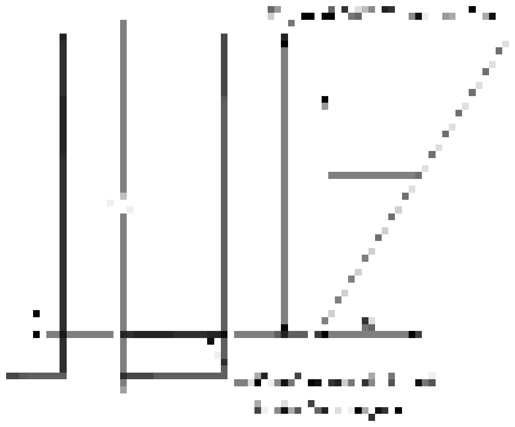
Figure 6.6.3 Strain distribution and net tensile strain
6.3.3.4
Sections are tension-controlled if the net tensile strain in the extreme tension steel, , is equal to or greater than 0.005 when the concrete in compression reaches its assumed strain limit of 0.003. Sections with between the compressioncontrolled strain limit and 0.005 constitute a transition region between compressioncontrolled and tension-controlled sections.6.3.3.5
Net tensile strain in the extreme tension steel at nominal strength, shall not be less than 0.004 for non prestressed flexural members and non prestressed members with factored axial compressive load less than .6.3.3.5.1
Use of compression reinforcement shall be permitted in conjunction with additional tension reinforcement to increase the strength of flexural members.6.3.3.6
For compression members, design axial strength shall not be taken greater than , computed by Eq. 6.6.8 or Eq. 6.6.9.6.3.3.6.1
For non prestressed members with spiral reinforcement conforming to Sec. 8.1 or composite members conforming to 6.3.13:6.3.3.6.2
For non prestressed members with tie reinforcement conforming to Sec. 8.1:6.3.3.7
Members subject to compressive axial load shall be designed for the maximum moment that can accompany the axial load. The factored axial force at given eccentricity shall not exceed the value that given in Sec 6.3.3.6. The maximum factored moment shall be magnified for slenderness effects in accordance with Sec 6.3.10.6.3.4 Spacing of Lateral Supports for Flexural Members
6.3.4.1
Distance between lateral supports for a beam shall not exceed 50 times , the least width of compression flange or face.6.3.4.2
Effects of lateral eccentricity of load shall be taken into account in determining spacing of lateral supports.6.3.5 Minimum Reinforcement for Members in Flexure
6.3.5.1
At every section of a flexural member where tensile reinforcement is required by analysis, except as provided in Sections 6.3.5.2 to 6.3.5.4, provided shall not be less than that given by Equations 6.6.10a and 6.6.10b.6.3.5.2
For statically determinate members with a flange in tension, shall not be less than the value given by Equations 6.6.10, except that is replaced by either or the width of flange, whichever is smaller.6.3.5.3
If, at every section, provided is at least one-third greater than that required by analysis, the requirements of Sections 6.3.5.1 and 6.3.5.2 need not be applied.6.3.5.4
For structural slabs and footings including raft that help support the structure vertically of uniform thickness, in the direction of the span shall be the same as that required by Sec 8.1.11. Maximum spacing of this reinforcement shall not exceed three times the thickness, nor 450 mm.6.3.6 Distribution of Flexural Reinforcement in One-Way Slabs and Beams
6.3.6.1
Rules for distribution of flexural reinforcement to control flexural cracking in beams and in one-way slabs (slabs reinforced to resist flexural stresses in only one direction) are prescribed in this section.6.3.6.2
Distribution of flexural reinforcement in two-way slabs shall be as required by Sec 6.5.3.6.3.6.3
As stated in Sec 6.3.6.4, flexural tension reinforcement shall be well distributed within maximum flexural tension zones of a member cross section.6.3.6.4
The spacing of reinforcement closest to the tension face, , shall be less than that given by But, shall not exceed, where, is the least distance from surface of reinforcement to the tension face. If there is only one bar or wire nearest to the extreme tension face, used in Eq. 6.6.11 is the width of the extreme tension face. Calculated stress in reinforcement closest to the tension face at service load shall be computed based on the unfactored moment. It shall be permitted to take as .6.3.6.5
For structures subject to very aggressive exposure or designed to be watertight, provisions of Sec 6.3.6.4 are not sufficient. For such structures, special investigations and precautions are required.6.3.6.6
When flanges of T-beam construction are in tension, part of the flexural tension reinforcement shall be distributed over an effective flange width as defined in Sec 6.1.13, or a width equal to one-tenth the span, whichever is smaller. If the effective flange width exceeds one-tenth the span, some longitudinal reinforcement shall be provided in the outer portions of the flange.6.3.6.7
Longitudinal skin reinforcement shall be uniformly distributed along both side faces of a member (Figure 6.6.4), where of a beam or joist exceeds 900 mm. Skin reinforcement shall extend for a distance from the tension face. The spacing shall be as provided in Sec 6.3.6.4, where is the least distance from the surface of the skin reinforcement to the side face. It shall be permitted to include such reinforcement in strength computations if a strain compatibility analysis is made to determine stress in the individual bars or wires.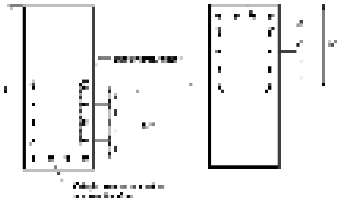
Figure 6.6.4 Skin reinforcement for beams and joists with h > 900 mm.
6.3.7 Deep Beams
6.3.7.1
Deep beams are members loaded on one face and supported on the opposite face so that compression struts can develop between the loads and the supports, and have either:- (a) Clear spans, , equal to or less than four times the overall member depth; or
- (b) Regions with concentrated loads within twice the member depth from the face of the support.
6.3.7.2
of deep beams shall be in accordance with Sec 6.4.6.6.3.7.3
Minimum area of flexural tension reinforcement, , shall conform to Sec 6.3.5.6.3.7.4
Minimum horizontal and vertical reinforcement in the side faces of deep beams shall satisfy either Sec I.3.3 or Sec 6.4.6.4 and Sec 6.4.6.5.6.3.8 Design Dimensions for Compression Members
6.3.8.1 Isolated compression member with multiple spirals
Outer limits of the effective cross section of a compression member with two or more interlocking spirals shall be taken at a distance outside the extreme limits of the spirals equal to the minimum concrete cover required by Sec 8.1.7.6.3.8.2 Monolithically built compression member with wall
Outer limits of the effective cross section of a spirally reinforced or tied reinforced compression member built monolithically with a concrete wall or pier shall be taken not greater than 40 mm outside the spiral or tie reinforcement.6.3.8.3 Equivalent circular compression member replacing other shapes
In lieu of using the full gross area for design of a compression member with a square, octagonal, or other shaped cross section, it shall be permitted to use a circular section with a diameter equal to the least lateral dimension of the actual shape. Gross area considered, required percentage of reinforcement, and design strength shall be based on that circular section.6.3.8.4 Limits of section
For a compression member with a cross section larger than required by considerations of loading, it shall be permitted to base the minimum reinforcement and strength on a reduced effective area not less than one-half the total area. This provision shall not apply to special moment frames or special structural walls designed in accordance with Sec. 8.3.6.3.9 Limits of Reinforcement for Compression Members
6.3.9.1
For noncomposite compression members, the area of longitudinal reinforcement, , shall be not less than or more than . To avoid practical difficulties in placing and compacting of concrete as well as to deliver ductility to noncomposite compression members, area of longitudinal reinforcement, , is preferred not to exceed unless absolutely essential.6.3.9.2
Minimum number of longitudinal bars in compression members shall be 4 for bars within rectangular or circular ties, 3 for bars within triangular ties, and 6 for bars enclosed by spirals conforming to Sec 6.3.9.3.6.3.9.3
Volumetric spiral reinforcement ratio, , shall be not less than the value given by Where the value of used in Eq. 6.6.12 shall not exceed 700 MPa. For greater than 420 MPa, lap splices according to 8.1.9.3(e) shall not be used.6.3.10 Slenderness Effects in Compression Members
6.3.10.1
Slenderness effects shall be permitted to be neglected in the following cases: (a) for compression members not braced against side sway when: (b) for compression members braced against side sway when: Where, is positive if the column is bent in single curvature, and negative if the member is bent in double curvature. Compression members may be considered to be braced against side sway when bracing elements have a total stiffness, resisting lateral movement of that story, of at least 12 times the gross stiffness of the columns within the story. The Jackson and Moreland Alignment Charts (Figure 6.6.5), which allow a graphical determination of for a column of constant cross section in a multibay frame may be used as the primary design aid to estimate the effective length factor . = ratio of of compression members to of flexural members in plane at one end of a compression member = span length of flexural member measured center to center of joints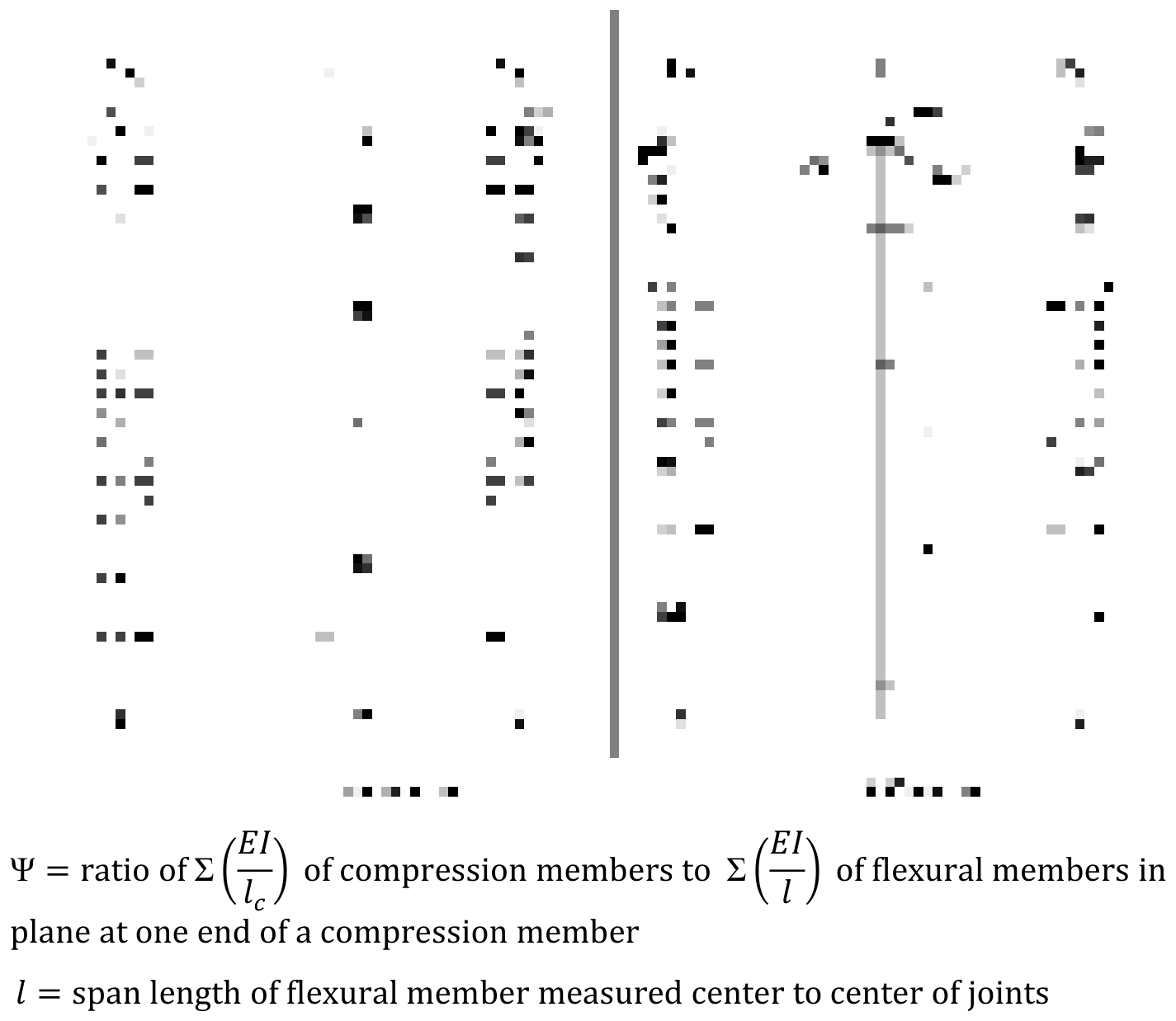
Figure 6.6.5 Effective length factors k.
6.3.10.1.1
The unsupported length of a compression member,l u , shall be taken as the clear distance between floor slabs, beams, or other members capable of providing lateral support in the direction being considered. Where column capitals or haunches are present, lu shall be measured to the lower extremity of the capital or haunch in the plane considered.6.3.10.1.2
It shall be permitted to take the radius of gyration, r equal to 0.30 times the overall dimension in the direction stability is being considered for rectangular compression members and 0.25 times the diameter for circular compression members. For other shapes, it shall be permitted to compute r for gross concrete section.6.3.10.2
When slenderness effects are not neglected as permitted by Sec 6.3.10.1, the design of compression members, restraining beams, and other supporting members shall be based on the factored forces and moments from a second-order analysis satisfying Sec 6.3.10.3, Sec 6.3.10.4, or Sec 6.3.10.5. These members shall also satisfy Sections 6.3.10.2.1 and 6.3.10.2.2. The dimensions of each member cross section used in the analysis shall be within 10 percent of the dimensions of the members shown on the design drawings or the analysis shall be repeated.6.3.10.2.1
Total moment including second-order effects in compression members, restraining beams, or other structural members shall not exceed 1.4 times the moment due to first-order effects.6.3.10.2.2
Second-order effects shall be considered along the length of compression members. It shall be permitted to account for these effects using the moment magnification procedure outlined in Sec 6.3.10.6.6.3.10.3 Nonlinear second-order analysis
Second-order analysis shall consider material nonlinearity, member curvature and lateral drift, duration of loads, shrinkage and creep, and interaction with the supporting foundation. The analysis procedure shall have been shown to result in prediction of strength in substantial agreement with results of comprehensive tests of columns in statically indeterminate reinforced concrete structures.6.3.10.4 Elastic second-order analysis
Elastic second-order analysis shall consider section properties determined taking into account the influence of axial loads, the presence of cracked regions along the length of the member, and the effects of load duration.6.3.10.4.1
It shall be permitted to use the following properties for the members in the structure: (a) Modulus of elasticity, from Sec 6.1.7.1; (b) Moments of inertia, as follows; and (c) Area6.3.10.4.2
When sustained lateral loads are present, for compression members shall be divided by . The term shall be taken as the ratio of maximum factored sustained shear within a story to the maximum factored shear in that story associated with the same load combination, but shall not be taken greater than 1.0.6.3.10.5 Procedure for moment magnification
Columns and stories in structures shall be designated as nonsway or sway columns or stories. The design of columns in nonsway frames or stories shall be based on Sec 6.3.10.6. The design of columns in sway frames or stories shall be based on Sec 6.3.10.7.6.3.10.5.1
A column in a structure shall be permitted to be assumed as nonsway if the increase in column end moments due to second-order effects does not exceed 5 percent of the first-order end moments.6.3.10.5.2
A story within a structure is permitted to be assumed as nonsway, if: Where and are the total factored vertical load and the horizontal story shear, respectively, in the story being evaluated, and is the first-order relative lateral deflection between the top and the bottom of that story due to .6.3.10.6 Procedure for moment magnification - nonsway
Compression members shall be designed for factored axial force and the factored moment amplified for the effects of member curvature where Where, And,6.3.10.6.1
EI shall be taken as Or, Alternatively, shall be permitted to compute the value of from Equation 6.6.15 dividing by .6.3.10.6.2
The term shall be taken as the ratio of maximum factored axial sustained load to maximum factored axial load associated with the same load combination, but shall not be taken greater than 1.0.6.3.10.6.3
The effective length factor, k shall be permitted to be taken as 1.0.6.3.10.6.4
For members with no transverse load between supports, shall be taken as Where, is positive if the column is bent in single curvature, and negative if the member is bent in double curvature. For members with transverse loads between supports, shall be taken as 1.0.6.3.10.6.5
Factored moment, , about each axis separately, in Equation 6.6.18 shall not be taken less than Where, is in mm and in N. For members in which exceeds , the value of in Equation 6.6.23 shall either be taken equal to 1.0, or shall be based on the ratio of the computed end moments, .6.3.10.7 Procedure for moment magnification - Sway
Moments and at the ends of an individual compression member shall be taken as Where, is computed according to Sec 6.3.10.7.3 or Sec 6.3.10.7.4.6.3.10.7.1
Flexural members shall be designed for the total magnified end moments of the compression members at the joint.6.3.10.7.2
The values of Ec and I given in Sec 6.3.10.4 shall be used for determining the effective length factor K and it shall not be less than 1.0.6.3.10.7.3
The moment magnifier shall be calculated as If calculated by Equation 6.6.27 exceeds 1.5, shall be calculated using second-order elastic analysis or 6.3.10.7.4.6.3.10.7.4
Alternatively, it shall be permitted to calculate as Where, is the summation for all the factored vertical loads in a story and is the summation for all sway-resisting columns in a storey. is calculated using Equation 6.6.20 with determined from Sec 6.3.10.7.2 and from Sec 6.3.10.6.1.6.3.11 Axially Loaded Members Supporting Slab System
Axially loaded members supporting a slab system included within the scope of Sec 6.5.1 shall be designed as provided in Sec. 6.3 and in accordance with the additional requirements of Sec. 6.5.6.3.12 Column Load Transmission through Floor System
If of a column is greater than 1.4 times that of the floor system, transmission of load through the floor system shall be provided by Sections 6.3.12.1, 6.3.12.2, or 6.3.12.3.6.3.12.1
Concrete of strength specified for the column shall be placed in the floor at the column location. Top surface of the column concrete shall extend 600 mm into the slab from face of column. Column concrete shall be well integrated with floor concrete, and shall be placed in accordance with relevant provisions for construction joints of columns, walls etc. with beams, slabs etc. To avoid accidental placing of lower strength concrete in the columns, the structural designer shall indicate on the drawing where the high and low strength concretes are to be placed.6.3.12.2
Strength of a column through a floor system shall be based on the lower value of concrete strength with vertical dowels and spirals as required.6.3.12.3
For columns laterally supported on four sides by beams of approximately equal depth or by slabs, it shall be permitted to base strength of the column on an assumed concrete strength in the column joint equal to 75 percent of column concrete strength plus 35 percent of floor concrete strength. In the application of Sec 6.3.12.3, ratio of column concrete strength to slab concrete strength shall not be taken larger than 2.5 in design.6.3.13 Composite Compression Members
6.3.13.1
All members reinforced longitudinally with structural steel shapes, pipe, or tubing with or without longitudinal bars shall be included in composite compression members.6.3.13.2
A composite member strength shall be computed for the same limiting conditions applicable to ordinary reinforced concrete members.6.3.13.3
Any axial load strength assigned to concrete of a composite member shall be transferred to the concrete by members or brackets in direct bearing on the composite member concrete.6.3.13.4
All axial load strength not assigned to concrete of a composite member shall be developed by direct connection to the structural steel shape, pipe, or tube.6.3.13.5
For evaluation of slenderness effects, radius of gyration, , of a composite section shall be not greater than the value given by And, as an alternative to a more accurate calculation, in Equation 6.6.20 shall be taken either as Equation 6.6.21 or6.3.13.6 Concrete core encased by structural steel
6.3.13.6.1
When a composite member is a structural steel encased concrete core, the thickness of the steel encasement shall be not less than for each face of width nor for circular sections of diameter6.3.13.6.2
When computing and , longitudinal bars located within the encased concrete core shall be permitted to be used.6.3.13.7 Spiral reinforcement around structural steel core
A composite member with spirally reinforced concrete around a structural steel core shall conform to Sections 6.3.13.7.1 to 6.3.13.7.4.6.3.13.7.1
Design yield strength of structural steel core shall be the specified minimum yield strength for the grade of structural steel used but not to exceed 350 MPa.6.3.13.7.2
Spiral reinforcement shall conform to Sec 6.3.9.3.6.3.13.7.3
Longitudinal bars located within the spiral shall be not less than 0.01 nor more than 0.06 times net area of concrete section.6.3.13.7.4
Longitudinal bars located within the spiral shall be permitted to be used in computing Asx and I sx .6.3.13.8 Tie reinforcement around structural steel core
Laterally tied concrete around a structural steel core forming a composite member shall conform to Sections 6.3.13.8.1 to 6.3.13.8.7.6.3.13.8.1
Design yield strength of structural steel core shall be the specified minimum yield strength for the grade of structural steel used but not to exceed 350 MPa.6.3.13.8.2
Lateral ties shall extend completely around the structural steel core.6.3.13.8.3
Lateral ties shall have a diameter not less than 0.02 times the greatest side dimension of composite member, except that ties shall not be smaller than 10 mm diameter and are not required to be larger than 16 mm diameter. Welded wire reinforcement of equivalent area shall be permitted.6.3.13.8.4
Vertical spacing of lateral ties shall not exceed 16 longitudinal bar diameters, 48 tie bar diameters, or 0.5 times the least side dimension of the composite member.6.3.13.8.5
Longitudinal bars located within the ties shall be not less than 0.01 nor more than 0.06 times net area of concrete section.6.3.13.8.6
A longitudinal bar shall be located at every corner of a rectangular cross section, with other longitudinal bars spaced not farther apart than one half the least side dimension of the composite member.6.3.13.8.7
Longitudinal bars located within the ties shall be permitted to be used in computing Asx and I sx .6.3.14 Bearing strength
6.3.14.1
Design bearing strength of concrete shall not exceed , except when the supporting surface is wider on all sides than the loaded area, then the design bearing strength of the loaded area shall be permitted to be multiplied by but by not more than 2 (Figure 6.6.6).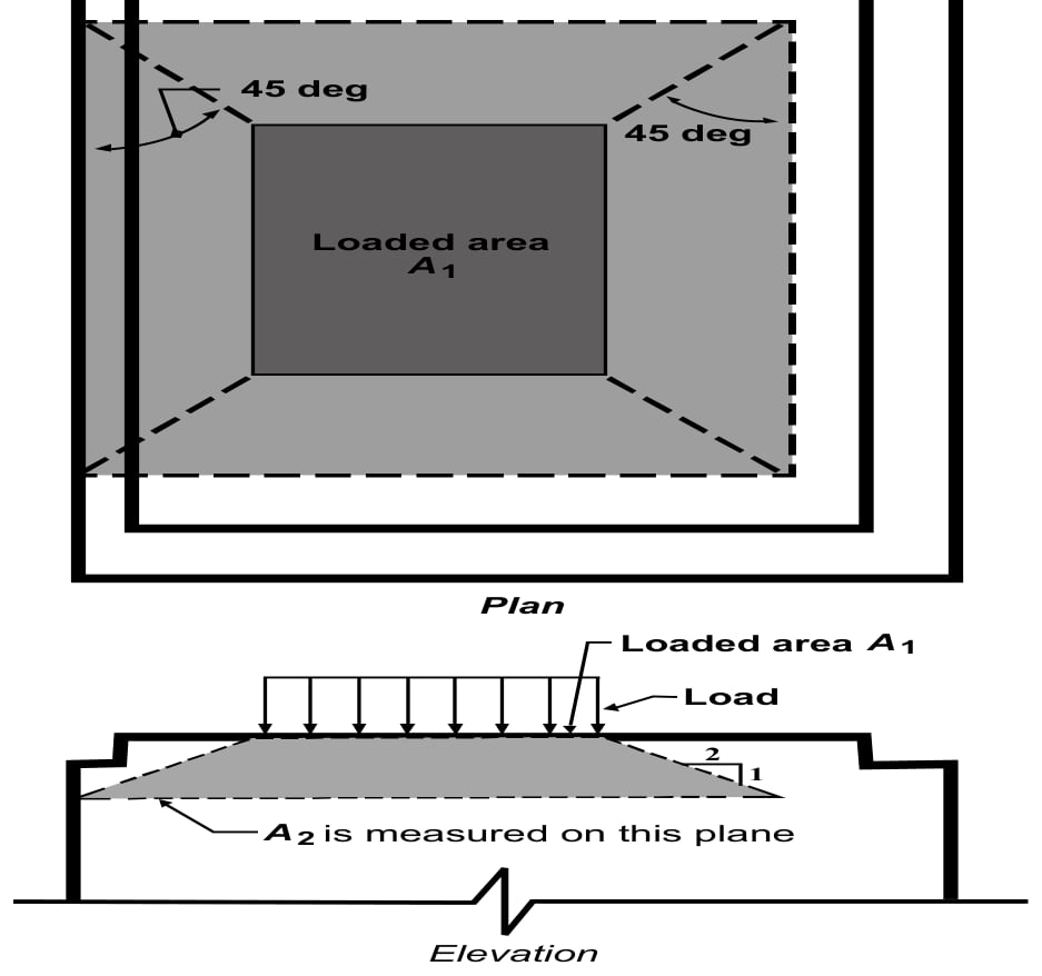
Figure 6.6.6 Determination of area A2 in stepped or sloped supports using frustum
6.3.15 Design for Flexure
6.3.15.1 Design of Rectangular Beams
- (a) Formula for singly reinforced beams: The following equations which are based on the simplified stress block of Sec 6.3.2.7, are applicable to singly reinforced rectangular beams along with T-beams where the neutral axis lies within the flange.
6.3.15.2 Design of T-Beams
- (a) General: For effective widths and other parameters for T, L or isolated beams, Sections 6.1.13.2 to 6.1.13.4 shall apply.
- (b) Formulae for T-beams : A T-beam shall be treated as a rectangular beam if where is obtained from Eq. 6.6.32 In using Eq. 6.6.32, if is not known, it may be initially assumed as :
6.4 Shear and Torsion
6.4.1 Shear Strength
6.4.1.1
Except for members designed in accordance with Appendix I, design of cross sections subject to shear shall be based on Where, is the factored shear force at the section considered and is nominal shear strength given by Where, is nominal shear strength provided by concrete calculated in accordance with Sec 6.4.2, or Sec 6.4.10, and is nominal shear strength provided by shear reinforcement calculated in accordance with Sec 6.4.3, Sec 6.4.8.9, or Sec 6.4.10.6.4.1.1.1
The effect of any openings in members shall be considered in determining Vn .6.4.1.1.2
In evaluating V c, whenever applicable, effects of axial tension due to creep and shrinkage in restrained members shall be considered and effects of inclined flexural compression in variable depth members shall be permitted to be included.6.4.1.2
Except as allowed in Sec 6.4.1.2.1, the values of used in this Chapter shall not exceed 8.3 MPa.6.4.1.2.1
Values of greater than 8.3 MPa shall be permitted in computing , , and for reinforced concrete beams and concrete joist construction having minimum web reinforcement in accordance with Sec 6.4.3.5.3, or Sec 6.4.4.5.2.6.4.1.3
Computation of maximum at supports in accordance with Sec 6.4.1.3.1 shall be permitted if all conditions (a), (b), and (c) are satisfied:- (a) Support reaction, in direction of applied shear, introduces compression into the end regions of member;
- (b) Loads are applied at or near the top of the member;
- (c) No concentrated load occurs between face of support and location of critical section defined in Sec 6.4.1.3.1.
6.4.1.3.1
Sections located less than a distance d from face of support shall be permitted to be designed for Vu computed at a distance d .6.4.1.4
For deep beams, brackets and corbels, walls, and slabs and footings, the special provisions of Sections 6.4.6 to 6.4.10 shall apply.6.4.2 Contribution of Concrete to Shear Strength
6.4.2.1
shall be computed by provisions of Sections 6.4.2.1.1 to 6.4.2.1.3, unless a more detailed calculation is made in accordance with Sec 6.4.2.2. Throughout this Chapter, except in Sec 6.4.5, shall be as defined in Sec 6.1.8.1.6.4.2.1.1
For members subject to shear and flexure only,6.4.2.1.2
For members subject to axial compression, Quantity shall be expressed in MPa.6.4.2.1.3
For members subject to significant axial tension, Vc shall be taken as zero unless a more detailed analysis is made using Sec 6.4.2.2.3.6.4.2.2
shall be permitted to be computed by more detailed calculation of Sections 6.4.2.2.1 to 6.4.2.2.3.6.4.2.2.1
For members subject to shear and flexure only, But, not greater than . When computing by Eq. 6.6.51, shall not be taken greater than 1.0, where occurs simultaneously with at section considered.6.4.2.2.2
For members subject to axial compression, it shall be permitted to compute using Eq. 6.6.51 with substituted for and not then limited to 1.0, where However, shall not be taken greater than shall be expressed in MPa. When as computed by Eq. 6.6.52 is negative, shall be computed by Eq. 6.6.53.6.4.2.2.3
For members subject to significant axial tension, But, not less than zero, where is negative for tension. shall be expressed in MPa.6.4.2.3
For circular members, the area used to compute shall be taken as the product of the diameter and effective depth of the concrete section. It shall be permitted to take as 0.80 times the diameter of the concrete section.6.4.3 Shear Strength Contribution of Reinforcement
6.4.3.1 Types of shear reinforcement
6.4.3.1.1
The following types of shear reinforcement shall be permitted:- (a) Stirrups perpendicular to axis of member;
- (b) Welded wire reinforcement with wires located perpendicular to axis of member;
- (c) Spirals, circular ties, or hoops.
- (d) Stirrups making an angle of 45o or more with longitudinal tension reinforcement;
- (e) Longitudinal reinforcement with bent portion making an angle of 30o or more with the longitudinal tension reinforcement;
- (f) Combinations of stirrups and bent longitudinal reinforcement.
6.4.3.2
The values of and used in design of shear reinforcement shall not exceed 420 MPa, except the value shall not exceed 550 MPa for welded deformed wire reinforcement.6.4.3.3
Stirrups and other bars or wires used as shear reinforcement shall extend to a distance from extreme compression fiber and shall be developed at both ends according to Sec 8.2.10.6.4.3.4 Limits in spacing for shear reinforcement
6.4.3.4.1
Spacing of shear reinforcement placed perpendicular to member axis shall not exceed nor 600 mm.6.4.3.4.2
The spacing of inclined stirrups and bent longitudinal reinforcement shall be such that every 45-degree line, extending toward the reaction from middepth of member to longitudinal tension reinforcement, shall be crossed by at least one line of shear reinforcement.6.4.3.4.3
Where, exceeds , maximum spacing given in Sections 6.4.3.4.1 and 6.4.3.4.2 shall be reduced by one-half.6.4.3.5 Minimum shear reinforcement
6.4.3.5.1
A minimum area of shear reinforcement, Av,min , shall be provided in all reinforced concrete flexural members, where Vu exceeds 0.5 Vc , except in members satisfying one or more of (a) to (f):- (a) Footings and solid slabs;
- (b) Hollow-core units with total untopped depth not greater than 315 mm and hollow-core units where is not greater than 0.5 Vcw ;
- (c) Concrete joist construction defined by Sec 6.1.14;
- (d) Beams with ℎ not greater than 250 mm;
- (e) Beam integral with slabs with ℎnot greater than 600 mm and not greater than the larger of 2.5 times thickness of flange, and 0.5 times width of web;
- (f) Beams constructed of steel fiber-reinforced, normal weight concrete with ′ not exceeding 40 MPa, ℎ not greater than 600 mm, and not greater than .
6.4.3.5.2
Minimum shear reinforcement requirements of Sec 6.4.3.5.1 shall be permitted to be waived if shown by test that required ph and can be developed when shear reinforcement is omitted. Such tests shall simulate effects of differential settlement, creep, shrinkage, and temperature change, based on a realistic assessment of such effects occurring in service.6.4.3.5.3
Where shear reinforcement is required by Sec 6.4.3.5.1 or for strength and where Sec 6.4.4.1 allows torsion to be neglected, shall be computed by But, shall not be less than .6.4.3.6 Design of shear reinforcement
6.4.3.6.1
Where Vu exceeds Vc , shear reinforcement shall be provided to satisfy Equations 6.6.47 and 6.6.48, where Vs shall be computed in accordance with Sections 6.4.3.6.2 to 6.4.3.6.9.6.4.3.6.2
Where shear reinforcement perpendicular to axis of member is used, Where, is the area of shear reinforcement within spacing .6.4.3.6.3
Where circular ties, hoops, or spirals are used as shear reinforcement, Vs shall be computed using Eq. 6.6.56 where d is defined in Sec 6.4.2.3 for circular members, A ν shall be taken as two times the area of the bar in a circular tie, hoop, or spiral at a spacing S , ø is measured in a direction parallel to longitudinal reinforcement, and fyt is the specified yield strength of circular tie, hoop, or spiral reinforcement.6.4.3.6.4
Where inclined stirrups are used as shear reinforcement, Where, is angle between inclined stirrups and longitudinal axis of the member, and is measured in direction parallel to longitudinal reinforcement.6.4.3.6.5
Where shear reinforcement consists of a single bar or a single group of parallel bars, all bent up at the same distance from the support, But, not greater than , where α is angle between bent-up reinforcement and longitudinal axis of the member.6.4.3.6.6
Where shear reinforcement consists of a series of parallel bent-up bars or groups of parallel bent-up bars at different distances from the support, Vs shall be computed by Eq. 6.6.57.6.4.3.6.7
Only the center three-fourths of the inclined portion of any longitudinal bent bar shall be considered effective for shear reinforcement.6.4.3.6.8
Where more than one type of shear reinforcement is used to reinforce the same portion of a member, Vs shall be computed as the sum of the values computed for the various types of shear reinforcement.6.4.3.6.9
shall not be taken greater than .6.4.4 Design for Torsion
Design for torsion shall be done as per Sections 6.4.4.1 to 6.4.4.6. A beam subjected to torsion is idealized as a thin-walled tube with the core concrete cross section in a solid beam neglected as shown in Figure 6.6.7.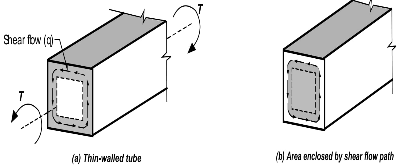
Figure 6.6.7 (a) Torsional resistance by thin-walled tube; (b) Ineffective inner area enclosed by shear flow path
6.4.4.1 Threshold torsion
It shall be permitted to neglect torsion effects if the factored torsional moment is less than:- (a) For members not subjected to axial tension or compression
- (b) For members subjected to an axial compressive or tensile force
6.4.4.1.1
For members cast monolithically with a slab and for isolated members with flanges, the overhanging flange width used to compute Acp and Ρcp shall conform to Sec 6.5.2.4, except that the overhanging flanges shall be neglected in cases where the parameter A2 cp / Ρcp calculated for a beam with flanges is less than that computed for the same beam ignoring the flanges.6.4.4.2 Evaluation of factored torsional moment
6.4.4.2.1
If the factored torsional moment, Tu , in a member is required to maintain equilibrium Figure 6.6.8 and exceeds the minimum value given in Sec 6.4.4.1, the member shall be designed to carry Tu in accordance with Sections 6.4.4.3 to 6.4.4.6.6.4.4.2.2
In a statically indeterminate structure where reduction of the torsional moment in a member can occur due to redistribution of internal forces upon cracking Figure 6.6.9, the maximum Tu shall be permitted to be reduced to the values given in (a), or (b) as applicable:- (a) For members, at the sections described in Sec 6.4.4.2.4 and not subjected to axial tension or compression
- (b) For members subjected to an axial compressive or tensile force
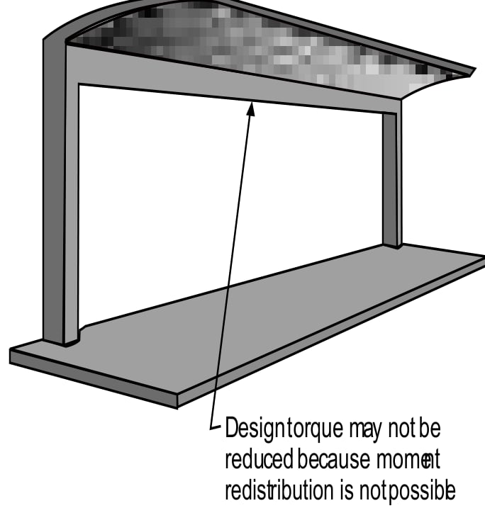
Figure 6.6.8 Design torque may not be reduced
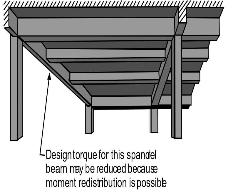
Figure 6.6.9 Design torque may be reduced
6.4.4.2.3
It shall be permitted to take the torsional loading from a slab as uniformly distributed along the member, if not determined by a more exact analysis.6.4.4.2.4
Sections located closer than a distance d from the face of a support shall be designed for not less than Tu computed at a distance d . If a concentrated torque occurs within this distance, the critical section for design shall be at the face of the support.6.4.4.3 Torsional moment strength
6.4.4.3.1
The cross-sectional dimensions shall be such that:- (a) For solid sections
- (b) For hollow sections
6.4.4.3.2
If the wall thickness varies around the perimeter of a hollow section, Eq. 6.6.60 shall be evaluated at the location where the left-hand side of Eq. 6.6.60 is a maximum.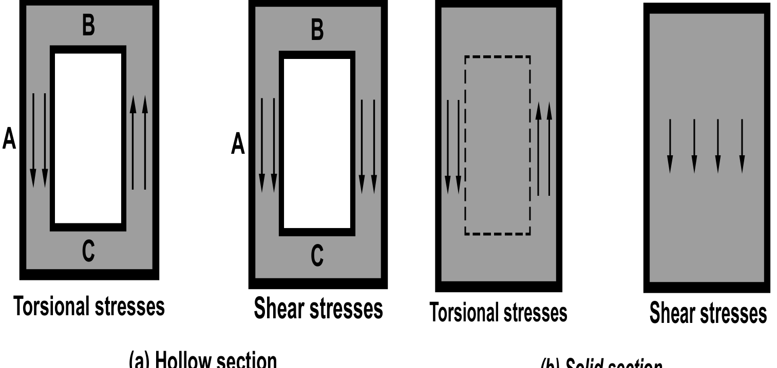
Figure 6.6.10 Superposition of torsional and shear stresses
6.4.4.3.3
If the wall thickness is less than , the second term in Eq. 6.4.14 shall be taken as Where, is the thickness of the wall of hollow section at the location where the stresses are being checked.6.4.4.3.4
The values of and used for design of torsional reinforcement shall not exceed 420 MPa.6.4.4.3.5
Where exceeds the threshold torsion, design of the cross section shall be based on6.4.4.3.6
shall be computed by Where, shall be determined by analysis except that it shall be permitted to take equal to 0.85; shall not be taken smaller than 30o nor larger than 60o . It shall be permitted to take θ equal to 45o .6.4.4.3.7
The additional area of longitudinal reinforcement to resist torsion, , shall not be less than Where, shall be the same value used in Eq. 6.6.62 and shall be taken as the amount computed from Eq. 6.6.62 not modified in accordance with Sec 6.4.4.5.2 or Sec 6.4.4.5.3; refers to closed transverse torsional reinforcement, and refers to longitudinal torsional reinforcement.6.4.4.3.8
Reinforcement required for torsion shall be added to that required for the shear, moment, and axial force that act in combination with the torsion. The most restrictive requirements for reinforcement spacing and placement shall be met.6.4.4.3.9
It shall be permitted to reduce the area of longitudinal torsion reinforcement in the flexural compression zone by an amount equal to , where occurs at the section simultaneously with , except that the reinforcement provided shall not be less than that required by Sec 6.4.4.5.3 or Sec 6.4.4.6.2.6.4.4.4 Details of torsional reinforcement
6.4.4.4.1
Torsion reinforcement shall consist of longitudinal bars or tendons and one or more of the following:- (a) Closed stirrups or closed ties, perpendicular to the axis of the member;
- (b) A closed cage of welded wire reinforcement with transverse wires perpendicular to the axis of the member;
- (c) Spiral reinforcement.
6.4.4.4.2
Transverse torsional reinforcement shall be anchored by one of the following:- (a) A 135o standard hook, or seismic hook as defined in Sec 8.1.2.1(d) Chapter 8, around a longitudinal bar;
- (b) According to Sec 8.2.10.2 Chapter 8 in regions where the concrete surrounding the anchorage is restrained against spalling by a flange or slab or similar member.
6.4.4.4.3
Longitudinal torsion reinforcement shall be developed at both ends.6.4.4.4.4
For hollow sections in torsion, the distance from the centerline of the transverse torsional reinforcement to the inside face of the wall of the hollow section shall not be less than 0.5 Aoh /P h .6.4.4.5 Minimum torsion reinforcement
6.4.4.5.1
A minimum area of torsional reinforcement shall be provided in all regions, where Tu exceeds the threshold torsion given in Sec 6.4.4.1.6.4.4.5.2
Where torsional reinforcement is required by Sec 6.4.4.5.1, the minimum area of transverse closed stirrups shall be computed by But, shall not be less than (0.35)⁄.6.4.4.5.3
Where torsional reinforcement is required by Sec 6.4.4.5.1, the minimum total area of longitudinal torsional reinforcement, Al,min , shall be computed by Where, shall not be taken less than 0.175y^⁄; refers to closed transverse torsional reinforcement, and refers to longitudinal reinforcement.6.4.4.6 Spacing of torsion reinforcement
6.4.4.6.1
The spacing of transverse torsion reinforcement shall not exceed the smaller of or 300 mm.6.4.4.6.2
The longitudinal reinforcement required for torsion shall be distributed around the perimeter of the closed stirrups with a maximum spacing of 300 mm. The longitudinal bars shall be inside the stirrups. There shall be at least one longitudinal bar in each corner of the stirrups. Longitudinal bars shall have a diameter at least 0.042 times the stirrup spacing, but not less than 10 mm diameter.6.4.4.6.3
Torsional reinforcement shall be provided for a distance of at least beyond the point required by analysis.6.4.5 Shear-Friction
6.4.5.1
Application of provisions of Sec 6.4.5 shall be for cases where it is appropriate to consider shear transfer across a given plane, such as: an existing or potential crack, an interface between dissimilar materials, or an interface between two concretes cast at different times.6.4.5.2
Design of cross sections subject to shear transfer as described in Sec 6.4.5.1 shall be based on Eq. 6.6.47, where is calculated in accordance with provisions of Sec 6.4.5.3 or Sec 6.4.5.4.6.4.5.3
A crack shall be assumed to occur along the shear plane considered. The required area of shear-friction reinforcement -M` across the shear plane shall be designed using either Sec 6.4.5.4 or any other shear transfer design methods that result in prediction of strength in substantial agreement with results of comprehensive tests.6.4.5.3.1
Provisions of Sections 6.4.5.5 to 6.4.5.10 shall apply for all calculations of shear transfer strength.6.4.5.4 Design method for shear-friction
6.4.5.4.1
Where shear-friction reinforcement is perpendicular to the shear plane, shall be computed by Where, is coefficient of friction in accordance with Sec 6.4.5.4.3.6.4.5.4.2
Where shear-friction reinforcement is inclined to the shear plane, such that the shear force produces tension in shear-friction reinforcement Figure 6.6.11, shall be computed by Where, is angle between shear-friction reinforcement and shear plane.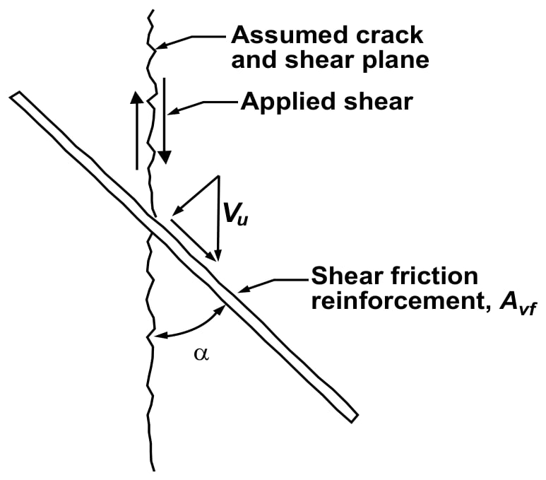
Figure 6.6.11 Shear-friction reinforcement at an angle to assumed crack
6.4.5.4.3
The coefficient of friction μ in Eq. 6.6.66 and Eq. 6.6.67 shall be taken as:- (a) Concrete placed monolithically
- (b) Concrete placed against hardened concrete with surface intentionally 1.0¥ roughened as specified in Sec 6.4.5.9
- (c) Concrete placed against hardened concrete not intentionally roughened
- (d) Concrete anchored to as-rolled structural steel by headed studs or by reinforcing bars (see 6.4.5.10)
6.4.5.5
For normal weight concrete either placed monolithically or placed against hardened concrete with surface intentionally roughened as specified in Sec 6.4.5.9, shall not exceed the smallest of 0.2′ -, (3.3 + 0.08′ )- and 11-, where - is area of concrete section resisting shear transfer. For all other cases, shall not exceed the smaller of 0.2′ - or 5.5- . Where concretes of different strengths are cast against each other, the value of ′ used to evaluate shall be that of the lowerstrength concrete.6.4.5.6
The value of used for design of shear-friction reinforcement shall not exceed 420 MPa.6.4.5.7
Net tension across shear plane shall be resisted by additional reinforcement. Permanent net compression across shear plane shall be permitted to be taken as additive to -M, the force in the shear-friction reinforcement, when calculating required -M.
6.4.5.8
Shear-friction reinforcement shall be appropriately placed along the shear plane and shall be anchored to develop on both sides by embedment, hooks, or welding to special devices.6.4.5.9
For the purpose of Sec 6.4.5, when concrete is placed against previously hardened concrete, the interface for shear transfer shall be clean and free of laitance. If ¦ is assumed equal to 1.0¥, interface shall be roughened to a full amplitude of approximately 6 mm.6.4.5.10
When shear is transferred between as-rolled steel and concrete using headed studs or welded reinforcing bars, steel shall be clean and free of paint.6.4.6 Deep Beams
6.4.6.1
The provisions of Sec 6.4.6 shall apply to members with not exceeding four times the overall member depth or regions of beams with concentrated loads within twice the member depth from the support that are loaded on one face and supported on the opposite face so that compression struts can develop between the loads and supports. See also Sec 8.2.7.6 Chapter 8.6.4.6.2
Deep beams shall be designed using provisions of either nonlinear analysis as permitted in Sec 6.3.7.1, or Appendix I.6.4.6.3
for deep beams shall not exceed .6.4.6.4
The area of shear reinforcement perpendicular to the flexural tension reinforcement, , shall not be less than , and shall not exceed the smaller of and 300 mm.6.4.6.5
The area of shear reinforcement parallel to the flexural tension reinforcement, , shall not be less than , and shall not exceed the smaller of and 300 mm.6.4.6.6
It shall be permitted to provide reinforcement satisfying Sec I.3.3 Appendix I instead of the minimum horizontal and vertical reinforcement specified in Sections 6.4.6.4 and 6.4.6.5.6.4.7 Provisions for Brackets and Corbels
6.4.7.1
Brackets and corbels, Figures 6.6.12 and 6.6.13, with a shear span-to-depth ratio less than 2 shall be permitted to be designed using Appendix I. Design shall be permitted using Sections 6.4.7.3 and 6.4.7.4 for brackets and corbels with:- (a) not greater than 1, and
- (b) Subject to factored horizontal tensile force, , not larger than .
6.4.7.2
Depth at outside edge of bearing area shall not be less than .6.4.7.3
Section at face of support shall be designed to resist simultaneously , a factored moment , and a factored horizontal tensile force .6.4.7.3.1
In all design calculations in accordance with Sec 6.4.7, shall be taken equal to 0.75.6.4.7.3.2
Design of shear-friction reinforcement, Aνf to resist Vu shall be in accordance with Sec 6.4.5.- (a) For normal weight concrete, shall not exceed the smallest of (i) , (ii) , and (iii) .
- (b) For all-lightweight or sand-lightweight concrete, shall not be taken greater than the smaller of and .
6.4.7.3.3
Reinforcement to resist factored moment shall be computed in accordance with Sections 6.3.2 and 6.3.3.
Figure 6.6.12 Structural action of a corbel
Figure 6.6.13 Notation used in Section 6.4.7
6.4.7.3.4
Reinforcement to resist factored tensile force shall be determined from . Factored tensile force, , shall not be taken less than unless provisions are made to avoid tensile forces. shall be regarded as live load even if tension results from restraint of creep, shrinkage, or temperature change.6.4.7.3.5
Area of primary tension reinforcement shall not be less than the larger of and .6.4.7.4
Total area, , of closed stirrups or ties parallel to primary tension reinforcement shall not be less than . Distribute uniformly within adjacent to primary tension reinforcement.6.4.7.5
shall not be less than .6.4.7.6
At front face of bracket or corbel, primary tension reinforcement shall be anchored by one of the following:- (a) By a structural weld to a transverse bar of at least equal size; weld to be designed to develop of primary tension reinforcement;
- (b) By bending primary tension reinforcement back to form a horizontal loop; or
- (c) By some other means of positive anchorage.
6.4.7.7
Bearing area on bracket or corbel neither shall project beyond straight portion of primary tension reinforcement, nor shall project beyond interior face of transverse anchor bar (if one is provided).6.4.8 Provisions for Walls
6.4.8.1
Design of walls for shear forces perpendicular to face of wall shall be in accordance with provisions for slabs in Sec 6.4.10. Design for horizontal in-plane shear forces in a wall shall be in accordance with Sections 6.4.8.2 to 6.4.8.9. Alternatively, it shall be permitted to design walls with a height not exceeding two times the length of the wall for horizontal shear forces in accordance with Appendix I and Sections 6.4.8.9.2 to 6.4.8.9.5.6.4.8.2
Design of horizontal section for shear in plane of wall shall be based on Equations 6.6.47 and 6.6.48, where shall be in accordance with Sec 6.4.8.5 or Sec 6.4.8.6 and shall be in accordance with Sec 6.4.8.9.6.4.8.3
at any horizontal section for shear in plane of wall shall not be taken greater than , where is thickness of wall, and is defined in Sec 6.4.8.4.6.4.8.4
For design for horizontal shear forces in plane of wall, shall be taken equal to . A larger value of , equal to the distance from extreme compression fiber to center of force of all reinforcement in tension, shall be permitted to be used when determined by a strain compatibility analysis.6.4.8.5
If a more detailed calculation is not made in accordance with Sec 6.4.8.6, shall not be taken greater than for walls subject to axial compression, or shall not be taken greater than the value given in 6.4.2.2.3 for walls subject to axial tension.6.4.8.6
shall be permitted to be the lesser of the values computed from Equations 6.6.68 and 6.6.69 Or, Where, is the overall length of the wall, and is positive for compression and negative for tension. If is negative, Eq. 6.6.69 shall not apply.6.4.8.7
Sections located closer to wall base than a distance or one-half the wall height, whichever is less, shall be permitted to be designed for the same as that computed at a distance or one-half the height.6.4.8.8
Where is less than 0.5, reinforcement shall be provided in accordance with Sec 6.4.8.9 or in accordance with Sec. 6.6. Where exceeds 0.5, wall reinforcement for resisting shear shall be provided in accordance with Sec 6.4.8.9.6.4.8.9 Design of shear reinforcement for walls
6.4.8.9.1
Where exceeds , horizontal shear reinforcement shall be provided to satisfy Equations 6.6.47 and 6.6.48, where shall be computed by Where, is area of horizontal shear reinforcement within spacing , and is determined in accordance with Sec 6.4.8.4. Vertical shear reinforcement shall be provided in accordance with Sec 6.4.8.9.4.6.4.8.9.2
Ratio of horizontal shear reinforcement area to gross concrete area of vertical section, shall not be less than 0.0025.6.4.8.9.3
Spacing of horizontal shear reinforcement shall not exceed the smallest of , , and 450 mm, where is the overall length of the wall.6.4.8.9.4
Ratio of vertical shear reinforcement area to gross concrete area of horizontal section, shall not be less than the larger of 0.0025 and the value obtained from: The value of calculated by Eq. 6.6.71 need not be greater than required by Sec 6.4.8.9.1. In Eq. 6.6.71, is the overall length of the wall, and is the overall height of the wall.6.4.8.9.5
Spacing of vertical shear reinforcement shall not exceed the smallest of , , and 450 mm, where is the overall length of the wall.6.4.9 Transfer of Moments to Columns
6.4.9.1
When gravity load, wind, earthquake, or other lateral forces cause transfer of moment at connections of framing elements to columns, the shear resulting from moment transfer shall be considered in the design of lateral reinforcement in the columns.6.4.9.2
Except for connections not part of a primary seismic load-resisting system that are restrained on four sides by beams or slabs of approximately equal depth, connections shall have lateral reinforcement not less than that required by Eq. 6.6.55 within the column for a depth not less than that of the deepest connection of framing elements to the columns. See also Sec. 8.1.13 Chapter 8.6.4.10 Provisions for Footings and Slabs
6.4.10.1
The shear strength of footings and slabs in the vicinity of columns, concentrated loads, or reactions is governed by the more severe of the following two conditions:6.4.10.1.1
Beam action where each critical section to be investigated extends in a plane across the entire width. The slab or footing shall be designed in accordance with Sections 6.4.1 to 6.4.3 for beam action.6.4.10.1.2
For two-way action, each of the critical sections to be investigated shall be located so that its perimeter bo is a minimum but need not approach closer thand to: 2- (a) Edges or corners of columns, concentrated loads, or reaction areas; and
- (b) Changes in slab thickness such as edges of capitals, drop panels, or shear caps.
6.4.10.1.3
For square or rectangular columns, concentrated loads, or reaction areas, the critical sections with four straight sides shall be permitted.6.4.10.2
For two-way action, the design of a slab or footing is based on Equations 6.6.47 and 6.6.48. shall be computed in accordance with Sec 6.4.10.2.1, or Sec 6.4.10.3.1. shall be computed in accordance with 6.4.10.3. For slabs with shearheads, shall be in accordance with Sec 6.4.10.4. Where moment is transferred between a slab and a column, Sec 6.4.10.6 shall apply.6.4.10.2.1
For slabs and footings, shall be the smallest of the values given by Equations 6.6.72, 6.6.73 and 6.6.74: Where, β is the ratio of long side to short side of the column, concentrated load or reaction area; Where, is 40 for interior columns, 30 for edge columns, 20 for corner columns; and6.4.10.3
Bars or wires and single- or multiple-leg stirrups as shear reinforcement shall be permitted in slabs and footings with greater than or equal to 150 mm, but not less than 16 times the shear reinforcement bar diameter. Shear reinforcement shall be in accordance with Sections 6.4.10.3.1 to 6.4.10.3.4.6.4.10.3.1
For computing , Eq. 6.6.48 shall be used and shall not be taken greater than and shall be calculated in accordance with Sec 6.4.3. In Eq. 6.6.56, shall be taken as the cross-sectional area of all legs of reinforcement on one peripheral line that is geometrically similar to the perimeter of column section.6.4.10.3.2
shall not be taken greater than .6.4.10.3.3
The distance from the column face to the first line of stirrup legs that surround the column shall not exceed . The spacing between adjacent stirrups legs in the first line of shear reinforcement shall not exceed 2 measured in a direction parallel to the column face. The spacing between successive lines of shear reinforcement that surround the column shall not exceed measured in a direction perpendicular to the column face. In a slab-column connection for which the moment transfer is negligible, the shear reinforcement should be symmetrical about the centroid of the critical section Figure 6.6.14. Spacing limits defined above are also shown in Figure 6.6.14 for interior column and in Figure 6.6.15 for edge column. At edge columns or for interior connections where moment transfer is significant, closed stirrups are recommended in a pattern as symmetrical as possible.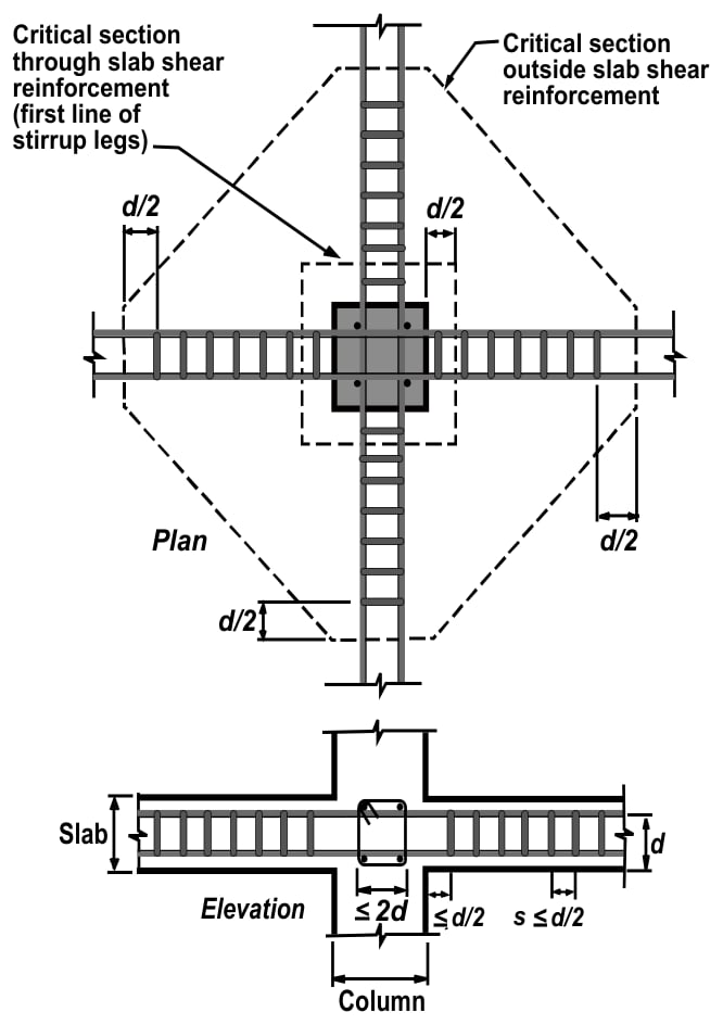
Figure 6.6.14 Arrangement of stirrup shear reinforcement around interior column
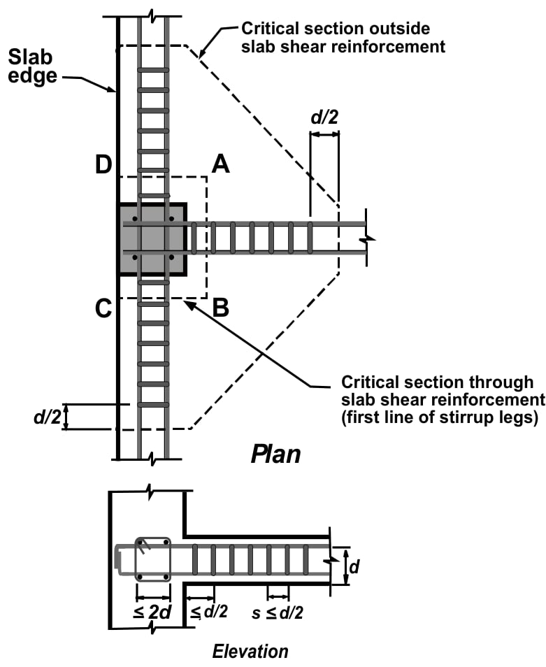
Figure 6.6.15 Arrangement of stirrup shear reinforcement around edge column
6.4.10.3.4
Slab shear reinforcement shall satisfy the anchorage requirements of Sec 8.2.10 Chapter 8 and shall engage the longitudinal flexural reinforcement in the direction being considered.6.4.10.4
Shear reinforcement consisting of structural steel I- or channel-shaped sections (shearheads) shall be permitted in slabs. The provisions of Sections 6.4.10.4.1 to 6.4.10.4.9 shall apply where shear due to gravity load is transferred at interior column supports. Where moment is transferred to columns, Sec 6.4.10.7.3 shall apply.6.4.10.4.1
Each shearhead shall consist of steel shapes fabricated by welding with a full penetration weld into identical arms at right angles. Shearhead arms shall not be interrupted within the column section.6.4.10.4.2
A shearhead shall not be deeper than 70 times the web thickness of the steel shape.6.4.10.4.3
The ends of each shearhead arm shall be permitted to be cut at angles not less than 30 degrees with the horizontal, provided the plastic moment strength of the remaining tapered section is adequate to resist the shear force attributed to that arm of the shearhead.6.4.10.4.4
All compression flanges of steel shapes shall be located within 0.3 d of compression surface of slab.6.4.10.4.5
The ratio between the flexural stiffness of each shearhead arm and that of the surrounding composite cracked slab section of width shall not be less than 0.15.6.4.10.4.6
Plastic moment strength, , required for each arm of the shearhead shall be computed by Where, is for tension-controlled members, is number of shearhead arms, and is minimum length of each shearhead arm required to comply with requirements of Sections 6.4.10.4.7 and 6.4.10.4.8.6.4.10.4.7
The critical slab section for shear shall be perpendicular to the plane of the slab and shall cross each shearhead arm at three-quarters the distance from the column face to the end of the shearhead arm. The critical section shall be located so that its perimeter is a minimum, but need not be closer than the perimeter defined in Sec 6.4.10.1.2(a).6.4.10.4.8
shall not be taken larger than on the critical section defined in Sec 6.4.10.4.7. When shearhead reinforcement is provided, shall not be taken greater than on the critical section defined in Sec 6.4.10.1.2(a).6.4.10.4.9
Moment resistance contributed to each slab column strip by a shearhead shall not be taken greater than Where, is for tension-controlled members, is number of shearhead arms, and is length of each shearhead arm actually provided. However, shall not be taken larger than the smallest of:- (a) 30 percent of the total factored moment required for each slab column strip;
- (b) The change in column strip moment over the length ;
- (c) computed by Eq. 6.6.75.
6.4.10.4.10
When unbalanced moments are considered, the shearhead must have adequate anchorage to transmit M p to the column.6.4.10.5
Headed shear stud reinforcement, placed perpendicular to the plane of a slab or footing, shall be permitted in slabs and footings in accordance with 6.4.10.5.1 through 6.4.10.5.4. The overall height of the shear stud assembly shall not be less than the thickness of the member less the sum of: (1) the concrete cover on the top flexural reinforcement; (2) the concrete cover on the base rail; and (3) one-half the bar diameter of the tension flexural reinforcement. Where flexural tension reinforcement is at the bottom of the section, as in a footing, the overall height of the shear stud assembly shall not be less than the thickness of the member less the sum of: (1) the concrete cover on the bottom flexural reinforcement; (2) the concrete cover on the head of the stud; and (3) one-half the bar diameter of the bottom flexural reinforcement.6.4.10.5.1
For the critical section defined in Sec 6.4.10.1.2, shall be computed using Eq. 6.6.48, with and not exceeding and respectively. shall be calculated using Eq. 6.6.56 with equal to the cross-sectional area of all the shear reinforcement on one peripheral line that is approximately parallel to the perimeter of the column section, where is the spacing of the peripheral lines of headed shear stud reinforcement. shall not be less than6.4.10.5.2
The spacing between the column face and the first peripheral line of shear reinforcement shall not exceed . The spacing between peripheral lines of shear reinforcement, measured in a direction perpendicular to any face of the column, shall be constant. For all slabs and footings, the spacing shall be based on the value of the shear stress due to factored shear force and unbalanced moment at the critical section defined in Sec 6.4.10.1.2, and shall not exceed:- (a) , where maximum shear stresses due to factored loads are less than or equal to ; and
- (b) , where maximum shear stresses due to factored loads are greater than .
6.4.10.5.3
The spacing between adjacent shear reinforcement elements, measured on the perimeter of the first peripheral line of shear reinforcement, shall not exceed .6.4.10.5.4
Shear stress due to factored shear force and moment shall not exceed at the critical section located outside the outermost peripheral line of shear reinforcement.6.4.10.6 Openings in slabs
If openings in slabs are located at a distance less than 10 times the slab thickness from a concentrated load or reaction area, or when openings in flat slabs are located within column strips as defined in Sec. 6.5, the critical slab sections for shear defined in Sections 6.4.10.1.2 and 6.4.10.4.7 shall be modified as follows:6.4.10.6.1
For slabs without shearheads, that part of the perimeter of the critical section that is enclosed by straight lines projecting from the centroid of the column, concentrated load, or reaction area and tangent to the boundaries of the openings shall be considered ineffective Figure 6.6.16.6.4.10.6.2
For slabs with shearheads, the ineffective portion of the perimeter shall be one-half of that defined in Sec 6.4.10.6.1.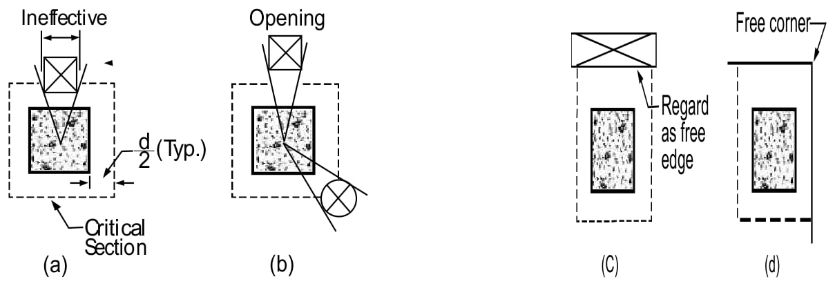
Figure 6.6.16 Effective perimeter (in dashed lines) to consider effect of openings and free edges
6.4.10.7 Transfer of moment in slab-column connections
6.4.10.7.1
Where gravity load, wind, earthquake, or other lateral forces cause transfer of unbalanced moment between a slab and column, shall be transferred by flexure in accordance with Sec 6.5.5.3. The remainder of the unbalanced moment, , shall be considered to be transferred by eccentricity of shear about the centroid of the critical section defined in Sec 6.4.10.1.2 where6.4.10.7.2
The shear stress resulting from moment transfer by eccentricity of shear shall be assumed to vary linearly about the centroid of the critical sections defined in Sec 6.4.10.1.2. The maximum shear stress due to and shall not exceed :- (a) For members without shear reinforcement,
- (b) For members with shear reinforcement other than shearheads,
6.4.10.7.3
When shear reinforcement consisting of structural steel I- or channelshaped sections (shearheads) is provided, the sum of the shear stresses due to vertical load acting on the critical section defined by Sec 6.4.10.4.7 and the shear stresses resulting from moment transferred by eccentricity of shear about the centroid of the critical section defined in Sec 6.4.10.1.2(a) and 6.4.10.1.3 shall not exceed .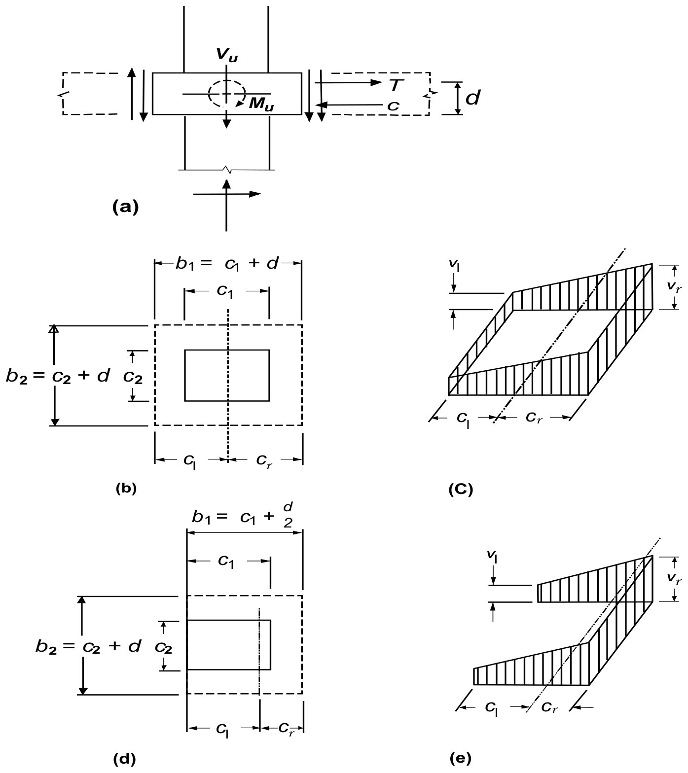
Figure 6.6.17 Transfer of moment from slab to column: (a) forces resulting from vertical load and unbalanced moment; (b) critical section for an interior column; (c) shear stress distribution for an interior column; (d) critical section for an edge column; (e) shear stress distribution for an edge column
6.5 Two-Way Slab Systems: Flat Plates, Flat Slabs and Edge-Supported Slabs
6.5.1 Scope
The provisions of this section shall apply to all slabs, solid, ribbed or hollow, spanning in more than one direction, with or without beams between the supports. Flat plate is a term normally attributed to slabs without beams and without drop panels, column capitals, or brackets. On the other hand, slabs without beams, but with drop panels, column capital or brackets are commonly known as flat slabs. While this section covers the requirements for all types of slabs, the provisions of Sec 6.5.8. Alternative Design of Two-way Edge-Supported slabs, may be used as an alternative for slabs supported on all four edges by walls, steel beams or monolithic concrete beams having a total depth not less than 3 times the slab thickness.6.5.1.1
For a slab system supported by columns or walls, dimensions q, and shall be based on an effective support area defined by the intersection of the bottom surface of the slab, or of the drop panel or shear cap if present, with the largest right circular cone, right pyramid, or tapered wedge whose surfaces are located within the column and the capital or bracket and are oriented no greater than 45o to the axis of the column.6.5.1.2
Minimum thickness of slabs designed in accordance with Sec. 6.5 shall be as required by Sec 6.2.5.3.6.5.2 General
6.5.2.1
Column strip is a design strip with a width on each side of a column centerline equal to 0.25 or 0.25, whichever is less. Column strip includes beams, if any.6.5.2.2
Middle strip is a design strip bounded by two column strips.6.5.2.3
A panel is bounded by column, beam, or wall centerlines on all sides.6.5.2.4
For monolithic or fully composite construction, a beam includes that portion of slab on each side of the beam extending a distance equal to the projection of the beam above or below the slab, whichever is greater, but not greater than four times the slab thickness (Figure 6.6.18).6.5.2.5
When used to reduce the amount of negative moment reinforcement over a column or minimum required slab thickness, a drop panel shall:- (a) project below the slab at least one-quarter of the adjacent slab thickness; and
- (b) extend in each direction from the centerline of support a distance not less than one-sixth the span length measured from center-to-center of supports in that direction.
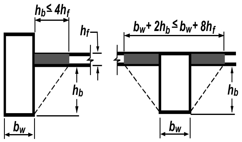
Figure 6.6.18 Portion of slab to be included with the beam
6.5.3 Slab Reinforcement
6.5.3.1
Area of reinforcement in each direction for two-way slab systems shall be determined from moments at critical sections, but shall not be less than required by Sec. 8.1.11.2 Chapter 8.6.5.3.2
Spacing of reinforcement at critical sections shall not exceed two times the slab thickness, except for portions of slab area of cellular or ribbed construction. In the slab over cellular spaces, reinforcement shall be provided as required by Sec. 8.1.11 Chapter 8.6.5.3.3
Positive moment reinforcement perpendicular to a discontinuous edge shall extend to the edge of slab and have embedment, straight or hooked, at least 150 mm in spandrel beams, columns, or walls.6.5.3.4
Negative moment reinforcement perpendicular to a discontinuous edge shall be bent, hooked, or otherwise anchored in spandrel beams, columns, or walls, and shall be developed at face of support according to provisions of Sec. 8.2 Chapter 8.6.5.3.5
Where a slab is not supported by a spandrel beam or wall at a discontinuous edge, or where a slab cantilevers beyond the support, anchorage of reinforcement shall be permitted within the slab.6.5.3.6
At exterior corners of slabs supported by edge walls or where one or more edge beams have a value of u` greater than 1.0, top and bottom slab reinforcement shall be provided at exterior corners in accordance with Sections 6.5.3.6.1 to 6.5.3.6.4 and as shown in Figure 6.6.19.6.5.3.6.1
Corner reinforcement in both top and bottom of slab shall be sufficient to resist a moment per unit of width equal to the maximum positive moment per unit width in the slab panel.6.5.3.6.2
The moment shall be assumed to be about an axis perpendicular to the diagonal from the corner in the top of the slab and about an axis parallel to the diagonal from the corner in the bottom of the slab.6.5.3.6.3
Corner reinforcement shall be provided for a distance in each direction from the corner equal to one-fifth the longer span.6.5.3.6.4
Corner reinforcement shall be placed parallel to the diagonal in the top of the slab and perpendicular to the diagonal in the bottom of the slab. Alternatively, reinforcement shall be placed in two layers parallel to the sides of the slab in both the top and bottom of the slab.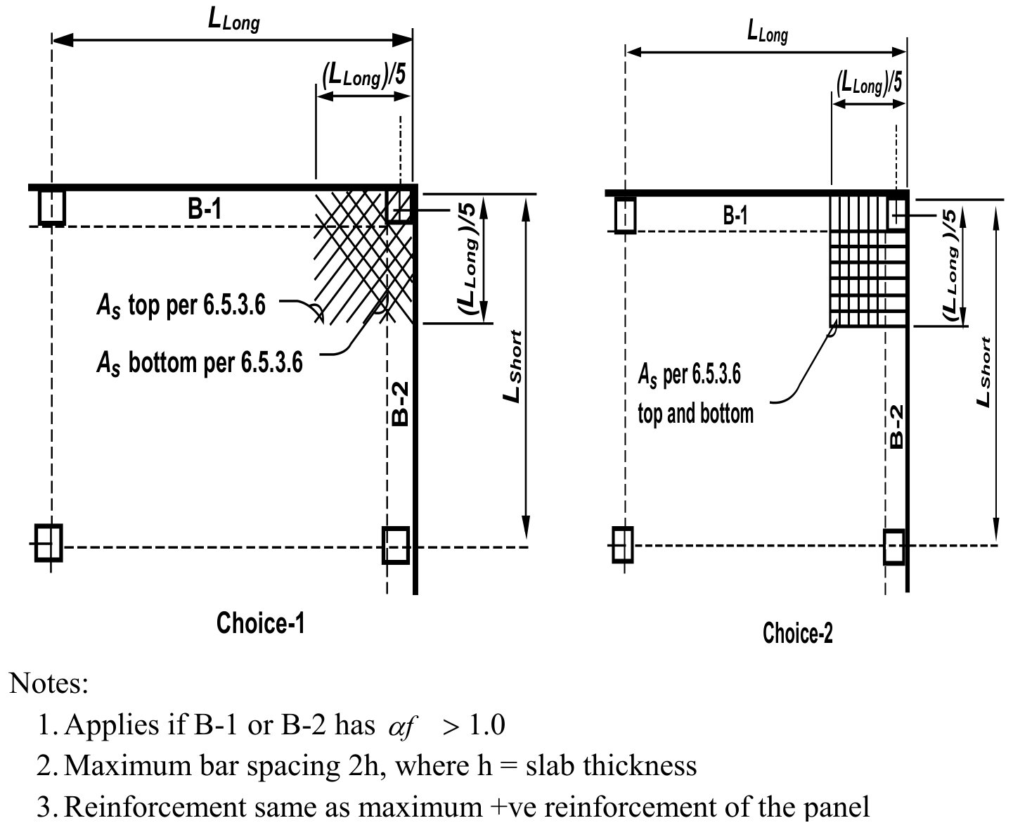
Figure 6.6.19 Corner reinforcement in slabs
6.5.3.7
When a drop panel is used to reduce the amount of negative moment reinforcement over the column of a flat slab, the dimensions of the drop panel shall be in accordance with Sec 6.5.2.5. In computing required slab reinforcement, the thickness of the drop panel below the slab shall not be assumed to be greater than one-quarter the distance from the edge of drop panel to the face of column or column capital.6.5.3.8 Details of reinforcement in slabs without beams
6.5.3.8.1
In addition to the other requirements of Sec 6.5.3, reinforcement in slabs without beams shall have minimum extensions as prescribed in Figure 6.6.20.6.5.3.8.2
Where adjacent spans are unequal, extensions of negative moment reinforcement beyond the face of support as prescribed in Figure 6.6.20 shall be based on requirements of the longer span.6.5.3.8.3
Bent bars shall be permitted only when depth-span ratio permits use of bends of 45 degrees or less.6.5.3.8.4
In frames where two-way slabs act as primary members resisting lateral loads, lengths of reinforcement shall be determined by analysis but shall not be less than those prescribed in Figure 6.6.20.6.5.3.8.5
All bottom bars or wires within the column strip, in each direction, shall be continuous or spliced with Class B tension splices or with mechanical or welded splices satisfying Sec. 8.2.12.3 Chapter 8. Splices shall be located as shown in Figure 6.6.20. At least two of the column strip bottom bars or wires in each direction shall pass within the region bounded by the longitudinal reinforcement of the column and shall be anchored at exterior supports.6.5.3.8.6
In slabs with shearheads and in lift-slab construction where it is not practical to pass the bottom bars required by 6.5.3.8.5 through the column, at least two bonded bottom bars or wires in each direction shall pass through the shearhead or lifting collar as close to the column as practicable and be continuous or spliced with a Class A splice. At exterior columns, the reinforcement shall be anchored at the shearhead or lifting collar.
Figure 6.6.20 Minimum extensions for reinforcement in slabs without beams for reinforcement extension into supports
6.5.4 Openings in Slab Systems
6.5.4.1
Openings of any size shall be permitted in slab systems if shown by analysis that the design strength is at least equal to the required strength set forth in Sections 6.2.2 and 6.2.3, and that all serviceability conditions, including the limits on deflections, are met.6.5.4.2
As an alternate to analysis required by Sec 6.5.4.1, openings shall be permitted in slab systems without beams only, in accordance with Sections 6.5.4.2.1 to 6.5.4.2.4.6.5.4.2.1
Openings of any size shall be permitted in the area common to intersecting middle strips, provided total amount of reinforcement required for the panel without the opening is maintained.6.5.4.2.2
In the area common to intersecting column strips, not more than oneeighth the width of column strip in either span shall be interrupted by openings. An amount of reinforcement equivalent to that interrupted by an opening shall be added on the sides of the opening.6.5.4.2.3
In the area common to one column strip and one middle strip, not more than one-quarter of the reinforcement in either strip shall be interrupted by openings. An amount of reinforcement equivalent to that interrupted by an opening shall be added on the sides of the opening.6.5.4.2.4
Shear requirements of Sec 6.4.10.6 shall be satisfied.6.5.5 Design Procedures
6.5.5.1
A slab system shall be designed by any procedure satisfying conditions of equilibrium and geometric compatibility, if shown that the design strength at every section is at least equal to the required strength set forth in Sections 6.2.2 and 6.2.3, and that all serviceability conditions, including limits on deflections, are met.6.5.5.1.1
Design of a slab system for gravity loads, including the slab and beams (if any) between supports and supporting columns or walls forming orthogonal frames, by either the Direct Design Method of Sec 6.5.6 or the Equivalent Frame Method of Sec 6.5.7, shall be permitted.6.5.5.1.2
For lateral loads, analysis of frames shall take into account effects of cracking and reinforcement on stiffness of frame members.6.5.5.1.3
Combining the results of the gravity load analysis with the results of the lateral load analysis shall be permitted.6.5.5.2
The slab and beams (if any) between supports shall be proportioned for factored moments prevailing at every section.6.5.5.3
When gravity load, wind, earthquake, or other lateral forces cause transfer of moment between slab and column, a fraction of the unbalanced moment shall be transferred by flexure in accordance with Sections 6.5.5.3.2 to 6.5.5.3.4.6.5.5.3.1
The fraction of unbalanced moment not transferred by flexure shall be transferred by eccentricity of shear in accordance with Sec 6.4.10.7.6.5.5.3.2
A fraction of the unbalanced moment given by shall be considered to be transferred by flexure within an effective slab width between lines that are one and one-half slab or drop panel thickness (1.5 h ) outside opposite faces of the column or capital, where M u is the factored moment to be transferred and6.5.5.3.3
For slabs with unbalanced moments transferred between the slab and columns, it shall be permitted to increase the value of γ f given by Eq. 6.6.81 in accordance with the following:- (a) For edge columns with unbalanced moments about an axis parallel to the edge, = 1.0 provided that at an edge support does not exceed 0.75, or at a corner support does not exceed 0.5.
- (b) For unbalanced moments at interior supports, and for edge columns with unbalanced moments about an axis perpendicular to the edge, increase to as much as 1.25 times the value from Eq. 6.6.81, but not more than = 1.0, provided that at the support does not exceed 0.4. The net tensile strain calculated for the effective slab width defined in Sec 6.5.5.3.2 shall not be less than 0.010.
6.5.5.3.4
Concentration of reinforcement over the column by closer spacing or additional reinforcement shall be used to resist moment on the effective slab width defined in Sec 6.5.5.3.2.6.5.5.4
Design for transfer of load from slabs to supporting columns or walls through shear and torsion shall be in accordance with Sec. 6.4.6.5.6 Direct Design Method
6.5.6.1 Limitations
Design of slab systems within the limitations of Sections 6.5.6.1.1 to 6.5.6.1.8 by the direct design method shall be permitted.6.5.6.1.1
There shall be a minimum of three continuous spans in each direction.6.5.6.1.2
Panels shall be rectangular, with a ratio of longer to shorter span centerto-center of supports within a panel not greater than 2.6.5.6.1.3
Successive span lengths center-to-center of supports in each direction shall not differ by more than one-third the longer span.6.5.6.1.4
Offset of columns by a maximum of 10 percent of the span (in direction of offset) from either axis between centerlines of successive columns shall be permitted.6.5.6.1.5
All loads shall be due to gravity only and uniformly distributed over an entire panel. The unfactored live load shall not exceed two times the unfactored dead load.6.5.6.1.6
For a panel with beams between supports on all sides, Eq. 6.6.82 shall be satisfied for beams in the two perpendicular directions. Where, and are calculated using respective stiffness parameters in accordance with the general Equation 6.6.83.6.5.6.1.7
Moment redistribution as permitted by Sec 6.1.6 shall not be applied for slab systems designed by the direct design method. See Sec 6.5.6.7.6.5.6.1.8
Variations from the limitations of Sec 6.5.6.1 shall be permitted if demonstrated by analysis that requirements of Sec 6.5.5.1 are satisfied.6.5.6.2 Total factored static moment for a span
6.5.6.2.1
Total factored static moment, M o , for a span shall be determined in a strip bounded laterally by centerline of panel on each side of centerline of supports.6.5.6.2.2
Absolute sum of positive and average negative factored moments in each direction shall not be less than Where, is length of clear span in direction that moments are being determined.6.5.6.2.3
Where the transverse span of panels on either side of the centerline of supports varies, l2 in Eq. 6.6.84 shall be taken as the average of adjacent transverse spans.6.5.6.2.4
When the span adjacent and parallel to an edge is being considered, the distance from edge to panel centerline shall be substituted for l2 in Eq. 6.6.84.6.5.6.2.5
Clear spanl nshall extend from face to face of columns, capitals, brackets, or walls. Value ofl nused in Eq. 6.6.84 shall not be less than 0.65 l1 . Circular or regular polygon-shaped supports shall be treated as square supports with the same area.6.5.6.3 Negative and positive factored moments
6.5.6.3.1
Negative factored moments shall be located at face of rectangular supports. Circular or regular polygon-shaped supports shall be treated as square supports with the same area.6.5.6.3.2
In an interior span, total static moment, M o , shall be distributed as follows: Negative factored moment: 0.65 Positive factored moment: 0.356.5.6.3.3
In an end span, total factored static moment, M o , shall be distributed as in Table 6.6.4 below: Table 6.6.4: Distribution of Total Factored Static Moment, M o in an End Span6.5.6.3.4
Negative moment sections shall be designed to resist the larger of the two interior negative factored moments determined for spans framing into a common support unless an analysis is made to distribute the unbalanced moment in accordance with stiffnesses of adjoining elements.6.5.6.3.5
Edge beams or edges of slab shall be proportioned to resist in torsion their share of exterior negative factored moments.6.5.6.3.6
The gravity load moment to be transferred between slab and edge column in accordance with 6.5.5.3.1 shall be .6.5.6.4 Factored moments in column strips
6.5.6.4.1
Column strips shall be proportioned to resist the portions in percent of interior negative factored moments as shown in Table 6.6.5.6.5.6.4.2
Column strips shall be proportioned to resist the portions in percent of exterior negative factored moments as shown in Table 6.6.6. Table 6.6.5: Portions of Interior Negative Moments to be resisted by Column Strip |Parameters||| |---|---|---|---| ||0.5|1.0|2.0| ||75|75|75| ||90|75|45| Notes: Linear interpolations shall be made between values shown. Interpolation function for % of Moment Table 6.6.6: Portions of Exterior Negative Moments to be resisted by Column Strip |Parameters|||| |---|---|---|---|---| |||0.5|1.0|2.0| |||100|100|100| |||75|75|75| |||100|100|100| |||90|75|45| Linear interpolations shall be made between values shown, where is calculated in Eq. 6.6.85 and is calculated in Eq. 6.6.86. The constant for T or L sections shall be permitted to be evaluated by dividing the section into separate rectangular parts, as defined in Sec 6.5.2.4, and summing the values of for each part. Interpolation function for % of Moment6.5.6.4.3
Where supports consist of columns or walls extending for a distance equal to or greater than 0.75l 2 used to compute M o , negative moments shall be considered to be uniformly distributed acrossl 2 .6.5.6.4.4
Column strips shall be proportioned to resist the portions in percent of positive factored moments shown in Table 6.6.7.6.5.6.4.5
For slabs with beams between supports, the slab portion of column strips shall be proportioned to resist that portion of column strip moments not resisted by beams. Table 6.6.7: Portions of Positive Moment to be resisted by Column Strip |Parameters||| |---|---|---|---| ||0.5|1.0|2.0| ||60|60|60| ||90|75|45| Notes: Linear interpolations shall be made between values shown. Interpolation function for % of Moment6.5.6.5 Factored moments in beams
6.5.6.5.1
Beams between supports shall be proportioned to resist 85 percent of column strip moments if α f 1 l 2/l 1 is equal to or greater than 1.0.6.5.6.5.2
For values of α f 1 l 2/l 1 between 1.0 and zero, proportion of column strip moments resisted by beams shall be obtained by linear interpolation between 85 and zero percent.6.5.6.5.3
In addition to moments calculated for uniform loads according to Sections 6.5.6.2.2, 6.5.6.5.1, and 6.5.6.5.2, beams shall be proportioned to resist all moments caused by concentrated or linear loads applied directly to beams, including weight of projecting beam stem above or below the slab.6.5.6.6 Factored moments in middle strips
6.5.6.6.1
That portion of negative and positive factored moments not resisted by column strips shall be proportionately assigned to corresponding half middle strips.6.5.6.6.2
Each middle strip shall be proportioned to resist the sum of the moments assigned to its two half middle strips.6.5.6.6.3
A middle strip adjacent to and parallel with a wall-supported edge shall be proportioned to resist twice the moment assigned to the half middle strip corresponding to the first row of interior supports.6.5.6.7 Modification of factored moments
Modification of negative and positive factored moments by 10 percent shall be permitted provided the total static moment for a panel, po, in the direction considered is not less than that required by Eq. 6.6.84.6.5.6.8 Factored shear in slab systems with beams
6.5.6.8.1
Beams with α f 1 l 2/l 1 equal to or greater than 1.0 shall be proportioned to resist shear caused by factored loads on tributary areas which are bounded by 45o lines drawn from the corners of the panels and the centerlines of the adjacent panels parallel to the long sides (Figure 6.6.21).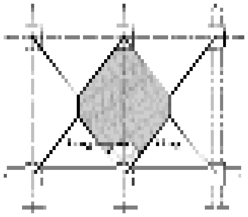
Figure 6.6.21 Tributary area for shear on an interior beam
6.5.6.8.2
In proportioning beams with α f 1 l 2/l 1 less than 1.0 to resist shear, linear interpolation, assuming beams carry no load atα f 1= 0, shall be permitted.6.5.6.8.3
In addition to shears calculated according to Sections 6.5.6.8.1 and 6.5.6.8.2, beams shall be proportioned to resist shears caused by factored loads applied directly on beams.6.5.6.8.4
Computation of slab shear strength on the assumption that load is distributed to supporting beams in accordance with Sec 6.5.6.8.1 or Sec 6.5.6.8.2 shall be permitted. Resistance to total shear occurring on a panel shall be provided.6.5.6.8.5
Shear strength shall satisfy the requirements of Sec. 6.4.6.5.6.9 Factored moments in columns and walls
6.5.6.9.1
Columns and walls built integrally with a slab system shall resist moments caused by factored loads on the slab system.6.5.6.9.2
At an interior support, supporting elements above and below the slab shall resist the factored moment specified by Eq. 6.6.87 in direct proportion to their stiffnesses unless a general analysis is made. Where, , , and refer to shorter span.6.5.7 Equivalent Frame Method
6.5.7.1
Design of slab systems by the equivalent frame method shall be based on assumptions given in Sections 6.5.7.2 to 6.5.7.6, and all sections of slabs and supporting members shall be proportioned for moments and shears thus obtained.6.5.7.1.1
Where metal column capitals are used, it shall be permitted to take account of their contributions to stiffness and resistance to moment and to shear.6.5.7.1.2
It shall be permitted to neglect the change in length of columns and slabs due to direct stress, and deflections due to shear.6.5.7.2 Equivalent frame
6.5.7.2.1
The structure shall be considered to be made up of equivalent frames on column lines taken longitudinally and transversely through the building (Figure 6.6.22).6.5.7.2.2
Each frame shall consist of a row of columns or supports and slab-beam strips, bounded laterally by the centerline of panel on each side of the center line of columns or supports.6.5.7.2.3
Columns or supports shall be assumed to be attached to slab-beam strips by torsional members (see Sec 6.5.7.5) transverse to the direction of the span for which moments are being determined and extending to bounding lateral panel centerlines on each side of a column.6.5.7.2.4
Frames adjacent and parallel to an edge shall be bounded by that edge and the centerline of adjacent panel.6.5.7.2.5
Analysis of each equivalent frame in its entirety shall be permitted. Alternatively, for gravity loading, a separate analysis of each floor or roof with far ends of columns considered fixed shall be permitted.6.5.7.2.6
Where slab-beams are analyzed separately, determination of moment at a given support assuming that the slab-beam is fixed at any support two panels distant therefrom, shall be permitted, provided the slab continues beyond that point.6.5.7.3 Slab-beams
6.5.7.3.1
Determination of the moment of inertia of slab-beams at any cross section outside of joints or column capitals using the gross area of concrete shall be permitted.6.5.7.3.2
Variation in moment of inertia along axis of slab-beams shall be taken into account.6.5.7.3.3
Moment of inertia of slab-beams from center of column to face of column, bracket, or capital shall be assumed equal to the moment of inertia of the slab-beam at face of column, bracket, or capital divided by the quantity 2 (1-c 2 / l 2) wherec 2andl 2are measured transverse to the direction of the span for which moments are being determined.6.5.7.4 Columns
6.5.7.4.1
Determination of the moment of inertia of columns at any cross section outside of joints or column capitals using the gross area of concrete shall be permitted.6.5.7.4.2
Variation in moment of inertia along axis of columns shall be taken into account (Figure 6.6.23).6.5.7.4.3
Moment of inertia of columns from top to bottom of the slab-beam at a joint shall be assumed to be infinite.6.5.7.5 Torsional members
6.5.7.5.1
Torsional members (see Sec 6.5.7.2.3) shall be assumed to have a constant cross section throughout their length consisting of the largest of (a), (b), and (c):- (a) A portion of slab having a width equal to that of the column, bracket, or capital in the direction of the span for which moments are being determined;
- (b) For monolithic or fully composite construction, the portion of slab specified in (a) plus that part of the transverse beam above and below the slab;
- (c) The transverse beam as defined in Sec 6.5.2.4.
6.5.7.5.2
Where beams frame into columns in the direction of the span for which moments are being determined, the torsional stiffness shall be multiplied by the ratio of the moment of inertia of the slab with such a beam to the moment of inertia of the slab without such a beam.6.5.7.5.3
Stiffness of the torsional members shall be calculated by the following expression: Where, and relate to the transverse span on each side of column.
Figure 6.6.22 Definitions of equivalent frame.
Figure 6.6.23 Equivalent column (column plus torsional members).
6.5.7.6 Arrangement of live load
6.5.7.6.1
When the loading pattern is known, the equivalent frame shall be analyzed for that load.6.5.7.6.2
When the unfactored live load is variable but does not exceed threequarters of the unfactored dead load, or the nature of live load is such that all panels will be loaded simultaneously, it shall be permitted to assume that maximum factored moments occur at all sections with full factored live load on entire slab system.6.5.7.6.3
For loading conditions other than those defined in Sec 6.5.7.6.2, it shall be permitted to assume that maximum positive factored moment near mid span of a panel occurs with three-quarters of the full factored live load on the panel and on alternate panels; and it shall be permitted to assume that maximum negative factored moment in the slab at a support occurs with three-quarters of the full factored live load on adjacent panels only.6.5.7.6.4
Factored moments shall be taken not less than those occurring with full factored live load on all panels.6.5.7.7 Factored moments
6.5.7.7.1
At interior supports, the critical section for negative factored moment (in both column and middle strips) shall be taken at face of rectilinear supports, but not farther away than 0.175 l 1 from the center of a column.6.5.7.7.2
At exterior supports with brackets or capitals, the critical section for negative factored moment in the span perpendicular to an edge shall be taken at a distance from face of supporting element not greater than one-half the projection of bracket or capital beyond face of supporting element.6.5.7.7.3
Circular or regular polygon-shaped supports shall be treated as square supports with the same area for location of critical section for negative design moment.6.5.7.7.4
Where slab systems within limitations of Sec 6.5.6.1 are analyzed by the equivalent frame method, it shall be permitted to reduce the resulting computed moments in such proportion that the absolute sum of the positive and average negative moments used in design need not exceed the value obtained from Eq. 6.6.84.6.5.7.7.5
Distribution of moments at critical sections across the slab-beam strip of each frame to column strips, beams, and middle strips as provided in Sections 6.5.6.4 to 6.5.6.6 shall be permitted if the requirement of Sec 6.5.6.1.6 is satisfied.6.5.8 Alternative Design of Two-Way Edge-Supported Slabs
6.5.8.1 General
The design method described in this Section shall be based on assumptions given in Sec 6.5.8.2 and 6.5.8.3, and all sections of slabs and supporting members shall be proportioned for moments and shears thus obtained.6.5.8.2 Scope and limitations
6.5.8.2.1
The provisions of this section may be used as alternative to those of Sections 6.5.1 to 6.5.7 for two-way slabs supported on all four edges by walls, steel beams or monolithic concrete beams having a total depth not less than 3 times the slab thickness.6.5.8.2.2
Panels shall be rectangular with a longer to shorter centre to centre support span ratio of not greater than 2.6.5.8.3 Analysis by the Coefficient Method
6.5.8.3.1
The negative moments and dead load and live load positive moments in the two directions shall be computed from Tables 6.6.8, 6.6.9 and 6.6.10 respectively. Shear in the slab and loads on the supporting beams shall be computed from Table 6.6.11. Table 6.6.8: Coefficients for Negative Moments in Slabs† Where, = total uniform dead plus live load per unit area| Span Ratio, | Moment Coefficient | Case 1 | Case 2 | Case 3 | Case 4 | Case 5 | Case 6 | Case 7 | Case 8 | Case 9 |
|---|---|---|---|---|---|---|---|---|---|---|
| 1.00 | 0.045 | 0.050 | 0.075 | 0.071 | 0.033 | 0.061 | ||||
| 0.045 | 0.076 | 0.050 | 0.071 | 0.061 | 0.033 | |||||
| 0.95 | 0.050 | 0.055 | 0.079 | 0.075 | 0.038 | 0.065 | ||||
| 0.041 | 0.072 | 0.045 | 0.067 | 0.056 | 0.029 | |||||
| 0.90 | 0.055 | 0.060 | 0.080 | 0.079 | 0.043 | 0.068 | ||||
| 0.037 | 0.070 | 0.040 | 0.062 | 0.052 | 0.025 | |||||
| 0.85 | 0.060 | 0.066 | 0.082 | 0.083 | 0.049 | 0.072 | ||||
| 0.031 | 0.065 | 0.034 | 0.057 | 0.046 | 0.021 | |||||
| 0.80 | 0.065 | 0.071 | 0.083 | 0.086 | 0.055 | 0.075 | ||||
| 0.027 | 0.061 | 0.029 | 0.051 | 0.041 | 0.017 | |||||
| 0.75 | 0.069 | 0.076 | 0.085 | 0.088 | 0.061 | 0.078 | ||||
| 0.022 | 0.056 | 0.024 | 0.044 | 0.036 | 0.014 | |||||
| 0.70 | 0.074 | 0.081 | 0.086 | 0.091 | 0.068 | 0.081 | ||||
| 0.017 | 0.050 | 0.019 | 0.038 | 0.029 | 0.011 | |||||
| 0.65 | 0.077 | 0.085 | 0.087 | 0.093 | 0.074 | 0.083 | ||||
| 0.014 | 0.043 | 0.015 | 0.031 | 0.024 | 0.008 | |||||
| 0.60 | 0.081 | 0.089 | 0.088 | 0.095 | 0.080 | 0.085 | ||||
| 0.010 | 0.035 | 0.011 | 0.024 | 0.018 | 0.006 | |||||
| 0.55 | 0.084 | 0.092 | 0.089 | 0.096 | 0.085 | 0.086 | ||||
| 0.007 | 0.028 | 0.008 | 0.019 | 0.014 | 0.005 | |||||
| 0.50 | 0.086 | 0.094 | 0.090 | 0.097 | 0.089 | 0.088 | ||||
| 0.006 | 0.022 | 0.006 | 0.014 | 0.010 | 0.003 |
| Span Ratio, | Moment Coefficient | Case 1 | Case 2 | Case 3 | Case 4 | Case 5 | Case 6 | Case 7 | Case 8 | Case 9 |
|---|---|---|---|---|---|---|---|---|---|---|
| 1.00 | 0.036 | 0.018 | 0.018 | 0.027 | 0.027 | 0.033 | 0.027 | 0.020 | 0.023 | |
| 0.036 | 0.018 | 0.027 | 0.027 | 0.018 | 0.027 | 0.033 | 0.023 | 0.020 | ||
| 0.95 | 0.040 | 0.020 | 0.021 | 0.030 | 0.028 | 0.036 | 0.031 | 0.022 | 0.024 | |
| 0.033 | 0.016 | 0.025 | 0.024 | 0.015 | 0.024 | 0.031 | 0.021 | 0.017 | ||
| 0.90 | 0.045 | 0.022 | 0.025 | 0.033 | 0.029 | 0.039 | 0.035 | 0.025 | 0.026 | |
| 0.029 | 0.014 | 0.024 | 0.022 | 0.013 | 0.021 | 0.028 | 0.019 | 0.015 | ||
| 0.85 | 0.050 | 0.024 | 0.029 | 0.036 | 0.031 | 0.042 | 0.040 | 0.029 | 0.028 | |
| 0.026 | 0.012 | 0.022 | 0.019 | 0.011 | 0.017 | 0.025 | 0.017 | 0.013 | ||
| 0.80 | 0.056 | 0.026 | 0.034 | 0.039 | 0.032 | 0.045 | 0.045 | 0.032 | 0.029 | |
| 0.023 | 0.011 | 0.020 | 0.016 | 0.009 | 0.015 | 0.022 | 0.015 | 0.010 | ||
| 0.75 | 0.061 | 0.028 | 0.040 | 0.043 | 0.033 | 0.048 | 0.051 | 0.036 | 0.031 | |
| 0.019 | 0.009 | 0.018 | 0.013 | 0.007 | 0.012 | 0.020 | 0.013 | 0.007 | ||
| 0.70 | 0.068 | 0.030 | 0.046 | 0.046 | 0.035 | 0.051 | 0.058 | 0.040 | 0.033 | |
| 0.016 | 0.007 | 0.016 | 0.011 | 0.005 | 0.009 | 0.017 | 0.011 | 0.006 | ||
| 0.65 | 0.074 | 0.032 | 0.054 | 0.050 | 0.036 | 0.054 | 0.065 | 0.044 | 0.034 | |
| 0.013 | 0.006 | 0.014 | 0.009 | 0.004 | 0.007 | 0.014 | 0.009 | 0.005 | ||
| 0.60 | 0.081 | 0.034 | 0.062 | 0.053 | 0.037 | 0.056 | 0.073 | 0.048 | 0.036 | |
| 0.010 | 0.004 | 0.011 | 0.007 | 0.003 | 0.006 | 0.012 | 0.007 | 0.004 | ||
| 0.55 | 0.088 | 0.035 | 0.071 | 0.056 | 0.038 | 0.058 | 0.081 | 0.052 | 0.037 | |
| 0.008 | 0.003 | 0.009 | 0.005 | 0.002 | 0.004 | 0.009 | 0.005 | 0.003 | ||
| 0.50 | 0.095 | 0.037 | 0.080 | 0.059 | 0.039 | 0.061 | 0.089 | 0.056 | 0.038 | |
| 0.006 | 0.002 | 0.007 | 0.004 | 0.001 | 0.003 | 0.007 | 0.004 | 0.002 |
| Span Ratio, | Moment Coefficient | Case 1 | Case 2 | Case 3 | Case 4 | Case 5 | Case 6 | Case 7 | Case 8 | Case 9 |
|---|---|---|---|---|---|---|---|---|---|---|
| 1.00 | 0.036 | 0.027 | 0.027 | 0.032 | 0.032 | 0.035 | 0.032 | 0.028 | 0.030 | |
| 0.036 | 0.027 | 0.032 | 0.032 | 0.027 | 0.032 | 0.035 | 0.030 | 0.028 | ||
| 0.95 | 0.040 | 0.030 | 0.031 | 0.035 | 0.034 | 0.038 | 0.036 | 0.031 | 0.032 | |
| 0.033 | 0.025 | 0.029 | 0.029 | 0.024 | 0.029 | 0.032 | 0.027 | 0.025 | ||
| 0.90 | 0.045 | 0.034 | 0.035 | 0.039 | 0.037 | 0.042 | 0.040 | 0.035 | 0.036 | |
| 0.029 | 0.022 | 0.027 | 0.026 | 0.021 | 0.025 | 0.029 | 0.024 | 0.022 | ||
| 0.85 | 0.050 | 0.037 | 0.040 | 0.043 | 0.041 | 0.046 | 0.045 | 0.040 | 0.039 | |
| 0.026 | 0.019 | 0.024 | 0.023 | 0.019 | 0.022 | 0.026 | 0.022 | 0.020 | ||
| 0.80 | 0.056 | 0.041 | 0.045 | 0.048 | 0.044 | 0.051 | 0.051 | 0.044 | 0.042 | |
| 0.023 | 0.017 | 0.022 | 0.020 | 0.016 | 0.019 | 0.023 | 0.019 | 0.017 | ||
| 0.75 | 0.061 | 0.045 | 0.051 | 0.052 | 0.047 | 0.055 | 0.056 | 0.049 | 0.046 | |
| 0.019 | 0.014 | 0.019 | 0.016 | 0.013 | 0.016 | 0.020 | 0.016 | 0.013 | ||
| 0.70 | 0.068 | 0.049 | 0.057 | 0.057 | 0.051 | 0.060 | 0.063 | 0.054 | 0.050 | |
| 0.016 | 0.012 | 0.016 | 0.014 | 0.011 | 0.013 | 0.017 | 0.014 | 0.011 | ||
| 0.65 | 0.074 | 0.053 | 0.064 | 0.062 | 0.055 | 0.064 | 0.070 | 0.059 | 0.054 | |
| 0.013 | 0.010 | 0.014 | 0.011 | 0.009 | 0.010 | 0.014 | 0.011 | 0.009 | ||
| 0.60 | 0.081 | 0.058 | 0.071 | 0.067 | 0.059 | 0.068 | 0.077 | 0.065 | 0.059 | |
| 0.010 | 0.007 | 0.011 | 0.009 | 0.007 | 0.008 | 0.011 | 0.009 | 0.007 | ||
| 0.55 | 0.088 | 0.062 | 0.080 | 0.072 | 0.063 | 0.073 | 0.085 | 0.070 | 00.063 | |
| 0.008 | 0.006 | 0.009 | 0.007 | 0.005 | 0.006 | 0.009 | 0.007 | 0.006 | ||
| 0.50 | 0.095 | 0.066 | 0.088 | 0.077 | 0.067 | 0.078 | 0.092 | 0.076 | 0.067 | |
| 0.006 | 0.004 | 0.007 | 0.005 | 0.004 | 0.005 | 0.007 | 0.005 | 0.004 |
| Span Ratio, | Load Ratio | Case 1 | Case 2 | Case 3 | Case 4 | Case 5 | Case 6 | Case 7 | Case 8 | Case 9 |
|---|---|---|---|---|---|---|---|---|---|---|
| 1.00 | 0.50 | 0.50 | 0.17 | 0.50 | 0.83 | 0.71 | 0.29 | 0.33 | 0.67 | |
| 0.50 | 0.50 | 0.83 | 0.50 | 0.17 | 0.29 | 0.71 | 0.67 | 0.33 | ||
| 0.95 | 0.55 | 0.55 | 0.20 | 0.55 | 0.86 | 0.75 | 0.33 | 0.38 | 0.71 | |
| 0.45 | 0.45 | 0.80 | 0.45 | 0.14 | 0.25 | 0.67 | 0.62 | 0.29 | ||
| 0.90 | 0.60 | 0.60 | 0.23 | 0.60 | 0.88 | 0.79 | 0.38 | 0.43 | 0.75 | |
| 0.40 | 0.40 | 0.77 | 0.40 | 0.12 | 0.21 | 0.62 | 0.57 | 0.25 | ||
| 0.85 | 0.66 | 0.66 | 0.28 | 0.66 | 0.90 | 0.83 | 0.43 | 0.49 | 0.79 | |
| 0.34 | 0.34 | 0.72 | 0.34 | 0.10 | 0.17 | 0.57 | 0.51 | 0.21 | ||
| 0.80 | 0.71 | 0.71 | 0.33 | 0.71 | 0.92 | 0.86 | 0.49 | 0.55 | 0.83 | |
| 0.29 | 0.29 | 0.67 | 0.29 | 0.08 | 0.14 | 0.51 | 0.45 | 0.17 | ||
| 0.75 | 0.76 | 0.76 | 0.39 | 0.76 | 0.94 | 0.88 | 0.56 | 0.61 | 0.86 | |
| 0.24 | 0.24 | 0.61 | 0.24 | 0.06 | 0.12 | 0.44 | 0.39 | 0.14 | ||
| 0.70 | 0.81 | 0.81 | 0.45 | 0.81 | 0.95 | 0.91 | 0.62 | 0.68 | 0.89 | |
| 0.19 | 0.19 | 0.55 | 0.19 | 0.05 | 0.09 | 0.38 | 0.32 | 0.11 | ||
| 0.65 | 0.85 | 0.85 | 0.53 | 0.85 | 0.96 | 0.93 | 0.69 | 0.74 | 0.92 | |
| 0.15 | 0.15 | 0.47 | 0.15 | 0.04 | 0.07 | 0.31 | 0.26 | 0.08 | ||
| 0.60 | 0.89 | 0.89 | 0.61 | 0.89 | 0.97 | 0.95 | 0.76 | 0.80 | 0.94 | |
| 0.11 | 0.11 | 0.39 | 0.11 | 0.03 | 0.05 | 0.24 | 0.20 | 0.06 | ||
| 0.55 | 0.92 | 0.92 | 0.69 | 0.92 | 0.98 | 0.96 | 0.81 | 0.85 | 0.95 | |
| 0.08 | 0.08 | 0.31 | 0.08 | 0.02 | 0.04 | 0.19 | 0.15 | 0.05 | ||
| 0.50 | 0.94 | 0.94 | 0.76 | 0.94 | 0.99 | 0.97 | 0.86 | 0.89 | 0.97 | |
| 0.06 | 0.06 | 0.24 | 0.06 | 0.01 | 0.03 | 0.14 | 0.11 | 0.03 |
6.5.8.4 Shear on Supporting Beam
The shear requirements provided in Sec 6.5.6.8 shall be satisfied.6.5.8.5 Deflection
Thickness of slabs supported on walls or stiff beams on all sides shall satisfy the requirements of Sec 6.2.5.3.6.5.8.6 Reinforcement
6.5.8.6.1
Area of reinforcement in each direction shall be determined from moments at critical sections but shall not be less than that required by Sec 8.1.11 Chapter 8.6.5.8.6.2
Spacing of reinforcement at critical sections shall not exceed two times the slab thickness, except for portions of slab area that may be of cellular or ribbed construction. In the slab over cellular spaces, reinforcement shall be provided as required by Sec 8.1.11 Chapter 8.6.5.8.6.3
Positive moment reinforcement perpendicular to a discontinuous edge shall extend to the edge of slab and have embedment, straight or hooked, at least 150 mm in spandrel beams, columns, or walls.6.5.8.6.4
Negative moment reinforcement perpendicular to a discontinuous edge shall be bent, hooked, or otherwise anchored, in spandrel beams, columns, or walls, and shall be developed at face of support according to provisions of Sec 8.2 Chapter 8.6.5.8.6.5 Corner reinforcement
Corner reinforcement shall be provided at exterior corners in both bottom and top of the slab, for a distance in each direction from the corner equal to one-fifth the longer span of the corner panel as per provisions of Sec 6.5.3.6.6.5.9 Ribbed and Hollow Slabs
6.5.9.1 General
The provisions of this section shall apply to slabs constructed in one of the ways described below:- (a) As a series of concrete ribs with topping cast on forms which may be removed after the concrete has set;
- (b) As a series of concrete ribs between precast blocks which remain part of the completed structure; the top of the ribs may be connected by a topping of concrete of the same strength as that used in the ribs;
- (c) Slabs with a continuous top and bottom face but containing voids of rectangular, oval or other shape.
6.5.9.2 Analysis and design
Any method of analysis which satisfies equilibrium and compatibility requirements may be used for ribbed and hollow slabs. Approximate moments and shears in continuous one-way ribbed or hollow slabs may be obtained from Sec 6.1.4.3. For two-way slabs, the unified design approach specified in Sec 6.5 Flat Plates, Flat Slabs and Edge-supported Slabs, shall be used.6.5.9.3 Shear
6.5.9.3.1
When burnt tile or concrete tile fillers of material having the same strength as the specified strength of concrete in the ribbed and hollow slabs are used permanently, it is permitted to include the vertical shells of fillers in contact with the ribs for shear and negative-moment strength computations, provided adequate bond between the two can be ensured.6.5.9.4 Deflection
The recommendations for deflection with respect to solid slabs may be applied to ribbed and hollow slab. Total depth of one-way ribbed and hollow slabs shall not be less than those required by Table 6.6.1 in Sec 6.2.5.2. For other slabs the provisions of Sec 6.2.5.3 shall apply.6.5.9.5 Size and Position of Ribs
In-situ-ribs shall be not less than 100 mm wide. They shall be spaced at centres not greater than 750 mm apart and their depth, excluding any topping, shall be not more than three and half times their width. Ribs shall be formed along each edge parallel to the span of one-way slabs.6.5.9.6 Reinforcement
The recommendations given in Sec 8.1.6 Chapter 8 regarding maximum distance between bars apply to areas of solid concrete in this form of construction. The curtailment, anchorage and cover to reinforcement shall be as specified below:- (a) At least 50 percent of the total main reinforcement shall be carried through the bottom on to the bearing and anchored in accordance with Sec 8.2.8 Chapter 8.
- (b) Where a slab, which is continuous over supports, has been designed as simply supported, reinforcement shall be provided over the support to control cracking. This reinforcement shall have a cross-sectional area of not less than one quarter of that required in the middle of the adjoining spans and shall extend at least one-tenth of the clear span into adjoining spans.
6.5.9.6.1
Adequate shear strength of slabs shall be provided in accordance with the requirements of Sec 6.4.10. For one-way ribbed and hollow slab construction, contribution of concrete to shear strength Vc is permitted to be 10 percent more than that specified in Sec 6.4.2. It is permitted to increase shear strength using shear reinforcement or by widening the ends of ribs.6.6 Walls
6.6.1 Scope
6.6.1.1
Provisions of Sec. 6.6 shall apply for design of walls subjected to axial load, with or without flexure.6.6.1.2
Cantilever retaining walls are designed according to flexural design provisions of Sec 6.3 with minimum horizontal reinforcement according to Sec 6.6.3.3.6.6.2 General
6.6.2.1
Walls shall be designed for eccentric loads and any lateral or other loads to which they are subjected.6.6.2.2
Walls subject to axial loads shall be designed in accordance with Sections 6.6.2, 6.6.3, and either Sec 6.6.4, Sec 6.6.5, or Sec 6.6.8.6.6.2.3
Design for shear shall be in accordance with Sec 6.4.8.6.6.2.4
Unless otherwise demonstrated by an analysis, the horizontal length of wall considered as effective for each concentrated load shall not exceed the smaller of the center-to-center distance between loads, and the bearing width plus four times the wall thickness.6.6.2.5
Compression members built integrally with walls shall conform to Sec 6.3.8.2.6.6.2.6
Walls shall be anchored to intersecting elements, such as floors and roofs; or to columns pilasters, buttresses, of intersecting walls; and to footings.6.6.2.7
Quantity of reinforcement and limits of thickness required by Sections 6.6.3 and 6.6.5 shall be permitted to be waived where structural analysis shows adequate strength and stability.6.6.2.8
Transfer of force to footing at base of wall shall be in accordance with Sec 6.8.8.6.6.3 Minimum reinforcement
6.6.3.1
Minimum vertical and horizontal reinforcement shall be in accordance with Sections 6.6.3.2 and 6.6.3.3 unless a greater amount is required for shear by Sections 6.4.8.8 and 6.4.8.9.6.6.3.2
Minimum ratio of vertical reinforcement area to gross concrete area, e, shall be:- (a) 0.0012 for deformed bars not larger than 16 mm diameter with not less than 420 MPa; or
- (b) 0.0015 for other deformed bars; or
- (c) 0.0012 for welded wire reinforcement not larger than MW200 or MD200.
6.6.3.3
Minimum ratio of horizontal reinforcement area to gross concrete area, , shall be:- (a) 0.0020 for deformed bars not larger than 16 mm diameter with not less than 420 MPa; or
- (b) 0.0025 for other deformed bars; or
- (c) 0.0020 for welded wire reinforcement not larger than MW200 or MD200.
6.6.3.4
Walls more than 250 mm thick, except basement walls, shall have reinforcement for each direction placed in two layers parallel with faces of wall in accordance with the following:- (a) One layer consisting of not less than one-half and not more than twothirds of total reinforcement required for each direction shall be placed not less than 50 mm nor more than one-third the thickness of wall from the exterior surface;
- (b) The other layer, consisting of the balance of required reinforcement in that direction, shall be placed not less than 20 mm nor more than onethird the thickness of wall from the interior surface.
6.6.3.5
Vertical and horizontal reinforcement shall not be spaced farther apart than three times the wall thickness, nor farther apart than 450 mm.6.6.3.6
Vertical reinforcement need not be enclosed by lateral ties if vertical reinforcement area is not greater than 0.01 times gross concrete area, or where vertical reinforcement is not required as compression reinforcement.6.6.3.7
In addition to the minimum reinforcement required by Sec 6.6.3.1, not less than two 16 mm diameter bars in walls having two layers of reinforcement in both directions and one 16 mm diameter bar in walls having a single layer of reinforcement in both directions shall be provided around window, door, and similar sized openings. Such bars shall be anchored to develop in tension at the corners of the openings.6.6.4 Design of Walls as Compression Members
Except as provided in Sec 6.6.5, walls subject to axial load or combined flexure and axial load shall be designed as compression members in accordance with provisions of Sections 6.3.2, 6.3.3, 6.3.10, 6.3.11, 6.3.14, 6.6.2, and 6.6.3.6.6.5 Empirical Method of Design
6.6.5.1
Walls of solid rectangular cross section shall be permitted to be designed by the empirical provisions of Sec 6.6.5 if the resultant of all factored loads is located within the middle third of the overall thickness of the wall and all limits of Sections 6.6.2, 6.6.3, and 6.6.5 are satisfied.6.6.5.2
Design axial strength of a wall satisfying limitations of Sec 6.6.5.1 shall be computed by Eq. 6.6.89 unless designed in accordance with 6.6.4. Where, shall correspond to compression-controlled sections in accordance with Sec 6.2.3.2.2 and effective length factor shall be:- (a) For walls braced top and bottom against lateral translation and
- Restrained against rotation at one or both ends (top, bottom, or 0.8
6.6.5.3 Minimum thickness of walls designed by empirical design method
6.6.5.3.1
Thickness of bearing walls shall not be less than 1/25 the supported height or length, whichever is shorter, nor less than 100 mm.6.6.5.3.2
Thickness of exterior basement walls and foundation walls shall not be less than 190 mm.6.6.6 Nonbearing Walls
6.6.6.1
Thickness of nonbearing walls shall not be less than 100 mm, nor less than 1/30 the least distance between members that provide lateral support.6.6.7 Walls as Grade Beams
6.6.7.1
Walls designed as grade beams shall have top and bottom reinforcement as required for moment in accordance with provisions of Sections 6.3.2 to 6.3.7. Design for shear shall be in accordance with provisions of Sec. 6.4.6.6.7.2
Portions of grade beam walls exposed above grade shall also meet requirements of Sec 6.6.3.6.6.8 Alternative Design of Slender Walls
6.6.8.1
When flexural tension controls the out-of-plane design of a wall, the requirements of Sec 6.6.8 are considered to satisfy Sec 6.3.10.6.6.8.2
Walls designed by the provisions of Sec 6.6.8 shall satisfy Sections 6.6.8.2.1 to 6.6.8.2.6.6.6.8.2.1
The wall panel shall be designed as a simply supported, axially loaded member subjected to an out-of-plane uniform lateral load, with maximum moments and deflections occurring at midspan.6.6.8.2.2
The cross section shall be constant over the height of the panel.6.6.8.2.3
The wall shall be tension-controlled.6.6.8.2.4
Reinforcement shall provide a design Strength Where, shall be obtained using the modulus of rupture, , given by Eq. 6.6.91.6.6.8.2.5
Concentrated gravity loads applied to the wall above the design flexural section shall be assumed to be distributed over a width:- (a) Equal to the bearing width, plus a width on each side that increases at a slope of 2 vertical to 1 horizontal down to the design section; but
- (b) Not greater than the spacing of the concentrated loads; and
- (c) Not extending beyond the edges of the wall panel.
6.6.8.2.6
Vertical stress at the midheight section shall not exceed .6.6.8.3
Design moment strength for combined flexure and axial loads at midheight shall be Where, is the maximum factored moment at midheight of wall due to lateral and eccentric vertical loads, not including effects, and is shall be obtained by iteration of deflections, or by Eq. 6.6.94. Where, And, the value of shall not be taken less than 6.6.6.8.4
Maximum out-of-plane deflection, , due to service loads, including effects, shall not exceed . If , maximum moment at midheight of wall due to service lateral and eccentric vertical loads, including effects, exceeds , shall be calculated by Eq. 6.6.96 If does not exceed , shall be calculated by Eq. 6.6.97 Where, shall be calculated by Eq. 6.6.95, and shall be obtained by iteration of deflections.6.7 Stairs
Stairs are the structural elements designed to connect different floors. The stairs shall be designed to meet the minimum load requirements. The flight arrangements, configuration and support conditions (Figure 6.6.24) shall govern the design procedure to follow.6.7.1 Stairs Supported at Floor and Landing Level
6.7.1.1 Effective span
The effective span of stairs without stringer beams shall be taken as the following horizontal distances:- (a) Centre to centre distance of beams, where supported at top and bottom risers by beams spanning parallel with the risers,
- (b) Where supported at the edge of a landing slab, which spans parallel with the risers, (Figure 6.6.25a) a distance equal to the going of the stairs plus at each end either half the width of the landing or 1.0m whichever is smaller. The going shall be measured horizontally.
- (c) Where the landing spans in the same direction of the stairs (Figure 6.6.25b), the span shall be the distance centre to centre of the supporting beams or walls.
- (d) Where the landing slabs, running at right angle to the direction of the flight, supported by walls or beams on three sides (Figure 6.6.25c), the effective span shall be going of the stair measured horizontally. Both positive and negative moments along the direction of the flight shall be calculated as q ⁄ , where w is the intensity of the total dead and live load per unit area 8 on a horizontal plane.

Figure 6.6.24 Different forms of stairs and landing arrangements
6.7.1.2 Loading
Staircases shall be designed to support the design ultimate load according to the load combinations specified in Chapter 2, loads.6.7.1.3 Distribution of loading
6.7.1.3.1Where flights or landing are embedded at least 110 mm into walls and are designed to span in the direction of the flight, a 150 mm strip may be deducted from the loaded area and the effective breadth of the section may be increased by 75 mm for the purpose of design (Figure 6.6.26) In the case of stairs with open wells, where spans cross at right angles, the load on areas common to any two such spans may be taken as one half in each direction as shown in Figure 6.6.27.6.7.1.4 Depth of section
The depth of the section shall be taken as the minimum thickness perpendicular to the soffit of the staircase.6.7.1.5 Design
6.7.1.5.1 Strength, deflection and crack control
The recommendations given in Sections 6.1 and 6.2 for beams and one-way slabs shall apply, except for the span/depth ratio of staircases without stringer beam where the provision of Sec 6.7.1.5.2 below shall apply.6.7.1.5.2 Permissible span/effective depth ratio for staircase without stringer beams
In case of stair flight that occupies at least 60% of the span, the ratio calculated in accordance with Sec 6.2.5.2 shall be increased by 15%.6.7.2 Special Types of Stairs
The provisions of special types of stairs like Free Standing (Landing unsupported), Sawtooth (Slabless) and Helicoidal are provided in Appendix M.
Figure 6.6.25 Effective Span for Stairs Supported at Each End by Landings

Figure 6.6.26 Loading on stairs Built in a wall
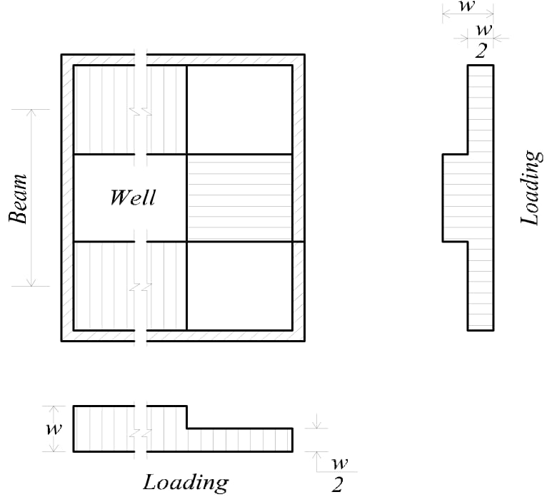
Figure 6.6.27 Loading of stairs with open wells
6.8 Footings
6.8.1 Scope
6.8.1.1
Provisions of Sec. 6.8 shall apply for design of isolated footings and, where applicable, to combined footings and mats.6.8.1.2
Additional requirements for design of combined footings and mats are given in Sec 6.8.10.6.8.2 Loads and Reactions
6.8.2.1
Footings shall be proportioned to resist the factored loads and induced reactions, in accordance with the appropriate design requirements of this Code and as provided in Sec. 6.8.6.8.2.2
Base area of footing or number and arrangement of piles shall be determined from unfactored forces and moments transmitted by footing to soil or piles and permissible soil pressure or permissible pile capacity determined using principles of soil mechanics.6.8.2.3
For footings on piles, computations for moments and shears shall be permitted to be based on the assumption that the reaction from any pile is concentrated at pile center.6.8.3
Equivalent Square Shapes for Circular or Regular Polygon-Shaped Columns or Pedestals Supported By Footings For location of critical sections for moment, shear, and development of reinforcement in footings, it shall be permitted to treat circular or regular polygon-shaped concrete columns or pedestals as square members with the same area.6.8.4 Moment in Footings
6.8.4.1
External moment on any section of a footing shall be determined by passing a vertical plane through the footing, and computing the moment of the forces acting over entire area of footing on one side of that vertical plane.6.8.4.2
Maximum factored moment, pk, for an isolated footing shall be computed as prescribed in Sec 6.8.4.1 at critical sections located as follows:- (a) At face of column, pedestal, or wall, for footings supporting a concrete column, pedestal, or wall;
- (b) Halfway between middle and edge of wall, for footings supporting a masonry wall;
- (c) Halfway between face of column and edge of steel base plate, for footings supporting a column with steel base plate.
6.8.4.3
In one-way footings and two-way square footings, reinforcement shall be distributed uniformly across entire width of footing.6.8.4.4
In two-way rectangular footings, reinforcement shall be distributed in accordance with Sections 6.8.4.4.1 and 6.8.4.4.2.6.8.4.4.1
Reinforcement in long direction shall be distributed uniformly across entire width of footing.6.8.4.4.2
For reinforcement in short direction, a portion of the total reinforcement, , shall be distributed uniformly over a band width (centered on centerline of column or pedestal) equal to the length of short side of footing. Remainder of reinforcement required in short direction, shall be distributed uniformly outside center band width of footing. Where, β is ratio of long to short sides of footing.6.8.5 Shear in Footings
6.8.5.1
Shear strength of footings supported on soil or rock shall be in accordance with Sec 6.4.10.6.8.5.2
Location of critical section for shear in accordance with Sec. 6.4 shall be measured from face of column, pedestal, or wall, for footings supporting a column, pedestal, or wall. For footings supporting a column or pedestal with steel base plates, the critical section shall be measured from location defined in Sec 6.8.4.2(c).6.8.5.3
Where the distance between axis of any pile to the axis of the column is more than two times the distance between the top of the pile cap and the top of the pile, the pile cap shall satisfy Sections 6.4.10 and 6.8.5.4. Other pile caps shall satisfy either Appendix I, or both Sections 6.4.10 and 6.8.5.4. If Appendix I is used, the effective concrete compression strength of the struts, !, shall be determined using Sec I.3.2.2(b).6.8.5.4
Computation of shear on any section through a footing supported on piles (Figure 6.6.28) shall be in accordance with Sections 6.8.5.4.1, 6.8.5.4.2, and 6.8.5.4.3. d 6.8.5.4.1 Entire reaction from any pile with its center located pile or more 2 outside the section shall be considered as producing shear on that section. d 6.8.5.4.2 Reaction from any pile with its center located pile or more inside 2 the section shall be considered as producing no shear on that section.6.8.5.4.3
For intermediate positions of pile center, the portion of the pile reaction to be considered as producing shear on the section shall be based on d straight-line interpolation between full value at pile outside the section and 2
Figure 6.6.28 Modified critical perimeter for shear with over-lapping critical perimeters.
6.8.6 Development of Reinforcement in Footings
6.8.6.1
Development of reinforcement in footings shall be in accordance with Sec. 8.2.6.8.6.2
Calculated tension or compression in reinforcement at each section shall be developed on each side of that section by embedment length, hook (tension only) or mechanical device, or a combination thereof.6.8.6.3
Critical sections for development of reinforcement shall be assumed at the same locations as defined in 6.8.4.2 for maximum factored moment, and at all other vertical planes where changes of section or reinforcement occur. See also 8.2.7.6.6.8.7 Minimum Footing Depth
Depth of footing above bottom reinforcement shall not be less than 150 mm for footings on soil, nor less than 300 mm for footings on piles.6.8.8 Force Transfer at Base of Column, Wall, or Reinforced Pedestal
6.8.8.1
Forces and moments at base of column, wall, or pedestal shall be transferred to supporting pedestal or footing by bearing on concrete and by reinforcement, dowels, and mechanical connectors.6.8.8.1.1
Bearing stress on concrete at contact surface between supported and supporting member shall not exceed concrete bearing strength for either surface as given by Sec 6.3.14.6.8.8.1.2
Reinforcement, dowels, or mechanical connectors between supported and supporting members shall be adequate to transfer:- (a) All compressive force that exceeds concrete bearing strength of either member;
- (b) Any computed tensile force across interface.
6.8.8.1.3
If calculated moments are transferred to supporting pedestal or footing, then reinforcement, dowels, or mechanical connectors shall be adequate to satisfy Sec 8.2.15.6.8.8.1.4
Lateral forces shall be transferred to supporting pedestal or footing in accordance with shear-friction provisions of Sec 6.4.5, or by other appropriate means.6.8.8.2
In cast-in-place construction, reinforcement required to satisfy Sec 6.8.8.1 shall be provided either by extending longitudinal bars into supporting pedestal or footing, or by dowels.6.8.8.2.1
For cast-in-place columns and pedestals, area of reinforcement across interface shall be not less than .0005 Ag , where Ag is the gross area of the supported member.6.8.8.2.2
For cast-in-place walls, area of reinforcement across interface shall be not less than minimum vertical reinforcement given in Sec 6.6.3.2.6.8.8.2.3
At footings, it shall be permitted to lap splice 43 mm diameter and 57 mm diameter longitudinal bars, in compression only, with dowels to provide reinforcement required to satisfy Sec 6.8.8.1. Dowels shall not be larger than 36 mm diameter bar and shall extend into supported member a distance not less than the larger ofl dc ’ of 43 mm diameter or 57 mm diameter bars and compression lap splice length of the dowels, whichever is greater, and into the footing a distance not less thanl dc of the dowels.6.8.8.2.4
If a pinned or rocker connection is provided in cast-in-place construction, connection shall conform to the provisions of Sections 6.8.8.1 and 6.8.8.3.6.8.8.3
In precast construction, anchor bolts or suitable mechanical connectors shall be permitted for satisfying 6.8.8.1. Anchor bolts shall be designed in accordance with Appendix K.6.8.8.3.1
Connection between precast columns or pedestals and supporting members shall meet the requirements of Sec 6.10.5.1.3(a).6.8.8.3.2
Connection between precast walls and supporting members shall meet the requirements of Sec 6.10.5.1.3(b) and (c).6.8.8.3.3
Anchor bolts and mechanical connections shall be designed to reach their design strength before anchorage failure or failure of surrounding concrete. Anchor bolts shall be designed in accordance with Appendix K.6.8.9 Stepped or Sloped Footings
6.8.9.1
In sloped or stepped footings, angle of slope or depth and location of steps shall be such that design requirements are satisfied at every section. (See also Sec 8.2.7.6.)6.8.9.2
Sloped or stepped footings designed as a unit shall be constructed to ensure action as a unit.6.8.10 Combined Footings and Mats
6.8.10.1
Footings supporting more than one column, pedestal, or wall (combined footings or mats) shall be proportioned to resist the factored loads and induced reactions, in accordance with appropriate design requirements of the Code.6.8.10.2
The direct design method of Sec. 6.5 shall not be used for design of combined footings and mats.6.8.10.3
Distribution of soil pressure under combined footings and mats shall be consistent with properties of the soil and the structure and with established principles of soil mechanics.6.8.10.4
Minimum reinforcing steel in mat foundations shall meet the requirements of Sec. 8.1.11.2 in each principal direction. Maximum spacing shall not exceed 450 mm.6.9 Folded Plates and Shells
6.9.1 Scope and Definitions
6.9.1.1
Provisions of Sec. 6.9 shall apply to thin shell and folded plate concrete structures, including ribs and edge members.6.9.1.2
All provisions of this Code not specifically excluded, and not in conflict with provisions of Sec. 6.9, shall apply to thin-shell structures.6.9.1.3 Thin shells
Three-dimensional spatial structures made up of one or more curved slabs or folded plates whose thicknesses are small compared to their other dimensions. Thin shells are characterized by their three-dimensional load-carrying behavior, which is determined by the geometry of their forms, by the manner in which they are supported, and by the nature of the applied load.6.9.1.4 Folded plates
A class of shell structure formed by joining flat, thin slabs along their edges to create a three-dimensional spatial structure.6.9.1.5 Ribbed shells
Spatial structures with material placed primarily along certain preferred rib lines, with the area between the ribs filled with thin slabs or left open.6.9.1.6 Auxiliary members
Ribs or edge beams that serve to strengthen, stiffen, or support the shell; usually, auxiliary members act jointly with the shell.6.9.1.7 Elastic analysis
An analysis of deformations and internal forces based on equilibrium, compatibility of strains, and assumed elastic behavior, and representing to a suitable approximation the three-dimensional action of the shell together with its auxiliary members.6.9.1.8 Inelastic analysis
An analysis of deformations and internal forces based on equilibrium, nonlinear stress-strain relations for concrete and reinforcement, consideration of cracking and time-dependent effects, and compatibility of strains. The analysis shall represent to a suitable approximation three-dimensional action of the shell together with its auxiliary members.6.9.1.9 Experimental analysis
An analysis procedure based on the measurement of deformations or strains, or both, of the structure or its model; experimental analysis is based on either elastic or inelastic behavior.6.9.2 Analysis and Design
6.9.2.1
Elastic behavior shall be an accepted basis for determining internal forces and displacements of thin shells. This behavior shall be permitted to be established by computations based on an analysis of the uncracked concrete structure in which the material is assumed linearly elastic, homogeneous, and isotropic. Poisson\phis ratio of concrete shall be permitted to be taken equal to zero.6.9.2.2
Inelastic analyses shall be permitted to be used where it can be shown that such methods provide a safe basis for design.6.9.2.3
Equilibrium checks of internal resistances and external loads shall be made to ensure consistency of results.6.9.2.4
Experimental or numerical analysis procedures shall be permitted where it can be shown that such procedures provide a safe basis for design.6.9.2.5
Approximate methods of analysis shall be permitted where it can be shown that such methods provide a safe basis for design.6.9.2.6
The thickness of a shell and its reinforcement shall be proportioned for the required strength and serviceability, using either the strength design method of Sec 6.1.2.1 or the design method of Sec 6.1.2.2.6.9.2.7
Shell instability shall be investigated and shown by design to be precluded.6.9.2.8
Auxiliary members shall be designed according to the applicable provisions of the Code. It shall be permitted to assume that a portion of the shell equal to the flange width, as specified in Sec 6.1.13, acts with the auxiliary member. In such portions of the shell, the reinforcement perpendicular to the auxiliary member shall be at least equal to that required for the flange of a T- beam by Sec 6.1.13.5.6.9.2.9
Strength design of shell slabs for membrane and bending forces shall be based on the distribution of stresses and strains as determined from either an elastic or an inelastic analysis.6.9.2.10
In a region where membrane cracking is predicted, the nominal compressive strength parallel to the cracks shall be taken as 0.4r .6.9.3 Design Strength of Materials
6.9.3.1
Specified compressive strength of concrete r at 28 days shall not be less than 21 MPa.6.9.3.2
Specified yield strength of reinforcement shall not exceed 420 MPa.6.9.4 Shell Reinforcement
6.9.4.1
Shell reinforcement shall be provided to resist tensile stresses from internal membrane forces, to resist tension from bending and twisting moments, to limit shrinkage and temperature crack width and spacing, and as reinforcement at shell boundaries, load attachments, and shell openings.6.9.4.2
Tensile reinforcement shall be provided in two or more directions and shall be proportioned such that its resistance in any direction equals or exceeds the component of internal forces in that direction. Alternatively, reinforcement for the membrane forces in the slab shall be calculated as the reinforcement required to resist axial tensile forces plus the tensile force due to shear-friction required to transfer shear across any cross section of the membrane. The assumed coefficient of friction, ¦, shall not exceed that specified in Sec 6.4.5.4.3.6.9.4.3
The area of shell reinforcement at any section as measured in two orthogonal directions shall not be less than the slab shrinkage or temperature reinforcement required by Sec 8.1.11.6.9.4.4
Reinforcement for shear and bending moments about axes in the plane of the shell slab shall be calculated in accordance with Sections 6.3, 6.4 and 6.5.6.9.4.5
The area of shell tension reinforcement shall be limited so that the reinforcement will yield before either crushing of concrete in compression or shell buckling can take place.6.9.4.6
In regions of high tension, membrane reinforcement shall, if practical, be placed in the general directions of the principal tensile membrane forces. Where this is not practical, it shall be permitted to place membrane reinforcement in two or more component directions.6.9.4.7
If the direction of reinforcement varies more than 10o from the direction of principal tensile membrane force, the amount of reinforcement shall be reviewed in relation to cracking at service loads.6.9.4.8
Where the magnitude of the principal tensile membrane stress within the shell varies greatly over the area of the shell surface, reinforcement resisting the total tension shall be permitted to be concentrated in the regions of largest tensile stress where it can be shown that this provides a safe basis for design. However, the ratio of shell reinforcement in any portion of the tensile zone shall be not less than 0.0035 based on the overall thickness of the shell.6.9.4.9
Reinforcement required to resist shell bending moments shall be proportioned with due regard to the simultaneous action of membrane axial forces at the same location. Where shell reinforcement is required in only one face to resist bending moments, equal amounts shall be placed near both surfaces of the shell even though a reversal of bending moments is not indicated by the analysis.6.9.4.10
Shell reinforcement in any direction shall not be spaced farther apart than 450 mm nor farther apart than five times the shell thickness. Where the principal membrane tensile stress on the gross concrete area due to factored loads exceeds , reinforcement shall not be spaced farther apart than three times the shell thickness.6.9.4.11
Shell reinforcement at the junction of the shell and supporting members or edge members shall be anchored in or extended through such members in accordance with the requirements of Sec. 8.2, except that the minimum development length shall be 1.2w but not less than 450 mm.6.9.4.12
Splice lengths of shell reinforcement shall be governed by the provisions of Sec. 8.2, except that the minimum splice length of tension bars shall be 1.2 times the value required by Sec. 8.2 but not less than 450 mm. The number of splices in principal tensile reinforcement shall be kept to a practical minimum. Where splices are necessary they shall be staggered at least w with not more than one-third of the reinforcement spliced at any section.6.9.5 Construction
6.9.5.1
When removal of formwork is based on a specific modulus of elasticity of concrete because of stability or deflection considerations, the value of the modulus of elasticity, , used shall be determined from flexural tests of fieldcured beam specimens. The number of test specimens, the dimensions of test beam specimens, and test procedures shall be specified by the Engineer.6.9.5.2
Contract documents shall specify the tolerances for the shape of the shell. If construction results in deviations from the shape greater than the specified tolerances, an analysis of the effect of the deviations shall be made and any required remedial actions shall be taken to ensure safe behavior.6.10 Precast Concrete
6.10.1 Scope
6.10.1.1
All provisions of this Code, not specifically excluded and not in conflict with the provisions of Sec 6.10, shall apply to structures incorporating precast concrete structural members.6.10.2 General
6.10.2.1
Design of precast members and connections shall include loading and restraint conditions from initial fabrication to end use in the structure, including form removal, storage, transportation, and erection.6.10.2.2
When precast members are incorporated into a structural system, the forces and deformations occurring in and adjacent to connections shall be included in the design.6.10.2.3
Tolerances for both precast members and interfacing members shall be specified. Design of precast members and connections shall include the effects of these tolerances.6.10.2.4
In addition to the requirements for drawings and specifications in Sec 1.9.3 of Chapter 1, the following (a) and (b) shall be included in either the contract documents or shop drawings:- (a) Details of reinforcement, inserts and lifting devices required to resist temporary loads from handling, storage, transportation, and erection;
- (b) Required concrete strength at stated ages or stages of construction.
6.10.3 Distribution of Forces in Members
6.10.3.1
Distribution of forces that are perpendicular to the plane of members shall be established by analysis or by test.6.10.3.2
Where the system behavior requires in-plane forces to be transferred between the members of a precast floor or wall system, Sections 6.10.3.2.1 and 6.10.3.2.2 shall apply.6.10.3.2.1
In-plane force paths shall be continuous through both connections and members.6.10.3.2.2
Where tension forces occur, a continuous path of steel or steel reinforcement shall be provided.6.10.4 Member Design
6.10.4.1
In one-way precast floor and roof slabs and in one-way precast, prestressed wall panels, all not wider than 3.7 m, and where members are not mechanically connected to cause restraint in the transverse direction, the shrinkage and temperature reinforcement requirements of Sec. 8.1.11 in the direction normal to the flexural reinforcement shall be permitted to be waived. This waiver shall not apply to members that require reinforcement to resist transverse flexural stresses.6.10.4.2
For precast, non prestressed walls the reinforcement shall be designed in accordance with the provisions of Sec 6.3 or Sec 6.6, except that the area of horizontal and vertical reinforcement each shall be not less than 0.001-U, where -U is the gross cross-sectional area of the wall panel. Spacing of reinforcement shall not exceed 5 times the wall thickness nor 750 mm for interior walls nor 450 mm for exterior walls.6.10.5 Structural Integrity
6.10.5.1
Except where the provisions of Sec 6.10.5.2 govern, the minimum provisions of Sec 6.10.5.1.1 to 6.10.5.1.4 for structural integrity shall apply to all precast concrete structures.6.10.5.1.1
Longitudinal and transverse ties required by Sec 8.1.12.3 shall connect members to a lateral load-resisting system.6.10.5.1.2
Where precast elements form floor or roof diaphragms, the connections between diaphragm and those members being laterally supported shall have a nominal tensile strength capable of resisting not less than 4.4 kN per linear m.6.10.5.1.3
Vertical tension tie requirements of Sec 8.1.12.3 shall apply to all vertical structural members, except cladding, and shall be achieved by providing connections at horizontal joints in accordance with (a) through (c):- (a) Precast columns shall have a nominal strength in tension not less than 1.4-U, in N. For columns with a larger cross section than required by consideration of loading, a reduced effective area -U(in mm2 ), based on cross-section required but not less than one-half the total area, shall be permitted;
- (b) Precast wall panels shall have a minimum of two ties per panel, with a nominal tensile strength not less than 44 kN per tie;
- (c) When design forces result in no tension at the base, the ties required by Sec 6.10.5.1.3(b) shall be permitted to be anchored into an appropriately reinforced concrete floor slab-on-ground.
6.10.5.1.4
Connection details that rely solely on friction caused by gravity loads shall not be used.6.10.5.2
For precast concrete bearing wall structures three or more stories in height, the minimum provisions of Sections 6.10.5.2.1 to 6.10.5.2.5 shall apply (Figure 6.6.29).6.10.5.2.1
Longitudinal and transverse ties shall be provided in floor and roof systems to provide a nominal strength of 22 kN per meter of width or length. Ties shall be provided over interior wall supports and between members and exterior walls. Ties shall be positioned in or within 600 mm of the plane of floor or roof system.6.10.5.2.2
Longitudinal ties parallel to floor or roof slab spans shall be spaced not more than 3 m on centers. Provisions shall be made to transfer forces around openings.6.10.5.2.3
Transverse ties perpendicular to floor or roof slab spans shall be spaced not greater than the bearing wall spacing.6.10.5.2.4
Ties around the perimeter of each floor and roof, within 1.2 m of the edge, shall provide a nominal strength in tension not less than 71 kN.6.10.5.2.5
Vertical tension ties shall be provided in all walls and shall be continuous over the height of the building. They shall provide a nominal tensile strength not less than 44 kN per horizontal meter of wall. Not less than two ties shall be provided for each precast panel.
Figure 6.6.29 Typical arrangement of tensile ties in large panel structures.
6.10.6 Connection and Bearing Design
6.10.6.1
Forces shall be permitted to be transferred between members by grouted joints, shear keys, mechanical connectors, reinforcing steel connections, reinforced topping, or a combination of these means.6.10.6.1.1
The adequacy of connections to transfer forces between members shall be determined by analysis or by test. Where shear is the primary result of imposed loading, it shall be permitted to use the provisions of Sec 6.4.5 as applicable.6.10.6.1.2
When designing a connection using materials with different structural properties, their relative stiffnesses, strengths, and ductilities shall be considered.6.10.6.2
Bearing for precast floor and roof members on simple supports shall satisfy Sections 6.10.6.2.1 and 6.10.6.2.2.6.10.6.2.1
The allowable bearing stress at the contact surface between supported and supporting members and between any intermediate bearing elements shall not exceed the bearing strength for either surface or the bearing element, or both. Concrete bearing strength shall be as given in Sec 6.3.14.6.10.6.2.2
Unless shown by test or analysis that performance will not be impaired, (a) and (b) shall be met (Figure 6.6.30):- (a) Each member and its supporting system shall have design dimensions selected so that, after consideration of tolerances, the distance from the edge of the support to the end of the precast member in the direction of the span is at least /180, but not less than:
- (b) Bearing pads at unarmored edges shall be set back a minimum of 13 mm from the face of the support, or at least the chamfer dimension at chamfered edges.
6.10.6.2.3
The requirements of Sec 8.2.8.1 shall not apply to the positive bending moment reinforcement for statically determinate precast members, but at least one-third of such reinforcement shall extend to the center of the bearing length, taking into account permitted tolerances in Sections 8.1.5.2c and 6.10.2.3.
Figure 6.6.30 Bearing length on support
6.10.7 Items Embedded after Concrete Placement
6.10.7.1
When approved by the designer, embedded items (such as dowels or inserts) that either protrude from the concrete or remain exposed for inspection shall be permitted to be embedded while the concrete is in a plastic state provided that Sections 6.10.7.1.1, 6.10.7.1.2, and 6.10.7.1.3 are met.6.10.7.1.1
Embedded items are not required to be hooked or tied to reinforcement within the concrete.6.10.7.1.2
Embedded items are maintained in the correct position while the concrete remains plastic.6.10.7.1.3
The concrete is properly consolidated around the embedded item.6.10.8 Marking and Identification
6.10.8.1
Each precast member shall be marked to indicate its location and orientation in the structure and date of manufacture.6.10.8.2
Identification marks shall correspond to placing drawings.6.10.9 Handling
6.10.9.1
Member design shall consider forces and distortions during curing, stripping, storage, transportation, and erection so that precast members are not overstressed or otherwise damaged.6.10.9.2
During erection, precast members and structures shall be adequately supported and braced to ensure proper alignment and structural integrity until permanent connections are completed.6.10.10 Evaluation of Strength of Precast Construction
6.10.10.1
A precast element to be made composite with cast-in-place concrete shall be permitted to be tested in flexure as a precast element alone in accordance with Sections 6.10.10.1.1 and 6.10.10.1.2. 6.10.10.1.1Test loads shall be applied only when calculations indicate the isolated precast element will not be critical in compression or buckling. 6.10.10.1.2The test load shall be that load which, when applied to the precast member alone, induces the same total force in the tension reinforcement as would be induced by loading the composite member with the test load required by Sec 6.11.3.2.6.10.10.2
The provisions of Sec 6.11.5 shall be the basis for acceptance or rejection of the precast element.6.11 Evaluation of Strength of Existing Structures
6.11.1 Strength Evaluation - General
6.11.1.1
If there is doubt that a part or all of a structure meets the safety requirements of this Code, a strength evaluation shall be carried out as required by the Engineer.6.11.1.2
If the effect of the strength deficiency is well understood and if it is feasible to measure the dimensions and material properties required for analysis, analytical evaluations of strength based on those measurements shall suffice. Required data shall be determined in accordance with Sec 6.11.2.6.11.1.3
If the effect of the strength deficiency is not well understood or if it is not feasible to establish the required dimensions and material properties by measurement, a load test shall be required if the structure is to remain in service.6.11.1.4
If the doubt about safety of a part or all of a structure involves deterioration, and if the observed response during the load test satisfies the acceptance criteria, the structure or part of the structure shall be permitted to remain in service for a specified time period. If deemed necessary by the Engineer, periodic reevaluations shall be conducted.6.11.2 Determination of Material Properties and Required Dimensions
6.11.2.1
Dimensions of the structural elements shall be established at critical sections.6.11.2.2
Locations and sizes of the reinforcing bars, welded wire reinforcement, or tendons shall be determined by measurement. It shall be permitted to base reinforcement locations on available drawings if spot checks are made confirming the information on the drawings.6.11.2.3
If required, concrete strength shall be based on results of cylinder tests from the original construction or tests of cores removed from the part of the structure where the strength is in question. For strength evaluation of an existing structure, cylinder or core test data shall be used to estimate an equivalent r . The method for obtaining and testing cores shall be in accordance with ASTM C42M.6.11.2.4
If required, reinforcement or prestressing steel strength shall be based on tensile tests of representative samples of the material in the structure in question.6.11.2.5
If the required dimensions and material properties are determined through measurements and testing, and if calculations can be made in accordance with Sec 6.11.1.2, it shall be permitted to increase φ from those specified in 6.2.3, but shall not be more than:6.11.3 Load Test Procedure
6.11.3.1 Load arrangement
The number and arrangement of spans or panels loaded shall be selected to maximize the deflection and stresses in the critical regions of the structural elements of which strength is in doubt. More than one test load arrangement shall be used if a single arrangement will not simultaneously result in maximum values of the effects (such as deflection, rotation, or stress) necessary to demonstrate the adequacy of the structure.6.11.3.2 Load intensity
The total test load (including dead load already in place) shall not be less than the larger of (a), (b), and (c):- (a) 1.15 D + 1.5 + 0.4()
- (b) 1.15 D + 0.9 + 1.5()
- (c)