
9.1 General
The Prestressed Concrete Structures Chapter of the Code is divided into the following three Divisions: Division A : Design Division B : Material and Construction Division C : Maintenance Division A : Scope, Definitions, Notation, Design And Analysis (Sections 9.2 To 9.18)9.2 Scope
9.2.1
Provisions of this Chapter shall apply to members prestressed with wires, strands, or bars conforming to the specifications of prestressing tendons given in Sec 9.5.1.3.9.2.2
All provisions of this Code not specifically excluded, and not in conflict with provisions of this Chapter 9, shall apply to prestressed concrete.9.3 Definitions, Symbols and Notation
9.3.1 Definitions
ACTION Mechanical force or environmental effect to which the structure (or structural component) is subjected. ANALYSIS Acceptable methods of evaluating the performance indices or verifying the compliance of specific criteria. ANCHORAGE In post-tensioning, a mechanical device used to anchor the tendon to the concrete; in pretensioning, a device used to anchor the tendon until the concrete has reached a pre-determined strength, and the prestressing force has been transferred to the concrete; for reinforcing bars, a length of reinforcement, or a mechanical anchor or hook, or combination thereof at the end of a bar needed to transfer the force carried by the bar into the concrete.9.3.2 Notation and Symbols
- = Area of the part of cross-section between flexural tension face and centre of gravity of gross section, mm2
- = Cross-sectional area of a structural member measured to the outside edges of transverse reinforcement, mm2
- = Gross area of concrete section, mm2 . For a hollow section, is the area of the concrete only and does not include the area of the void(s)
- = Area of prestressed reinforcement in tension zone, mm2
- = Area of nonprestressed tension reinforcement, mm2
- = Area of compression reinforcement, mm2
- = Clear cover of reinforcement, mm
- = Dead loads, or related internal moments and forces
- = Moment of inertia of cross-section resisting externally applied factored loads, mm4
- = Moment of inertia of cracked section transformed to concrete, mm4, Sec 6.
- = Moment of inertia of gross concrete section about centroidal axis, neglecting reinforcement, mm4
- = Effective moment of inertia for computation of deflection, mm4
- = Wobble friction coefficient per meter of prestressing tendon
- = Live loads, or related internal moments and forces
- = Maximum moment in member due to service loads at stage deflection is computed, N-mm
- = Moment causing flexural cracking at section due to externally applied loads, N-mm
- = Maximum factored moment at section due to externally applied loads, N-mm
- = Factored moment at section, N-mm
- = Tensile force in concrete due to unfactored dead load plus live load (D + L), N
- = Prestressing tendon force at jacking end, N
- = Inherent or possessed performance index
- = Inherent or possessed performance index
- = Prestressing tendon force at any point x
- = Nominal shear strength provided by concrete, N
- = Nominal shear strength provided by concrete when diagonal cracking results from combined shear and moment, N
- = Nominal shear strength provided by concrete when diagonal cracking results from excessive principal tensile stress in web, N
- = Shear force at section due to unfactored dead load, N
- = Factored shear force at section due to externally applied loads occurring simultaneously with , N
- = Nominal shear strength, N
- = Vertical component of effective prestress force at section, N
- = Nominal shear strength provided by shear reinforcement, N
- = Factored shear force at section, N
- = Shorter overall dimension of rectangular part of cross-section
- = Depth of equivalent rectangular stress block, mm
- = Width of compression face of member, mm
- = Distance from extreme compression fiber to centroid of nonprestressed tension reinforcement, mm
- = Distance from extreme compression fiber to centroid of compression reinforcement, mm
- = Nominal diameter of bar, wire, or prestressing strand, mm
- = Distance from extreme compression fiber to centroid of prestressed reinforcement, mm
- = Base of Napierian logarithm
- = Specified compressive strength of concrete, N/mm2
- = Compressive strength of concrete at transfer of prestress, N/mm2
- = Stress due to unfactored dead load, at extreme fiber of section where tensile stress is caused by externally applied loads, N/mm2
- = Compressive stress in concrete due to effective prestress forces only (after allowance for all prestress losses) at extreme fiber of section where tensile stress is caused by externally applied loads, N/mm2
- = Average compressive stress in concrete due to effective prestress force only (after allowance for all prestress losses), N/mm2
- = Stress in prestressed reinforcement at nominal strength, N/mm2
- = Specified tensile strength of prestressing tendons, N/mm2
- = Specified yield strength of prestressing tendons, N/mm2
- = Modulus of rupture of concrete, N/mm2
- = Effective stress in prestressed reinforcement (after allowance for all prestress losses), N/mm2
- = Extreme fiber stress in tension in the pre-compressed tensile zone calculated at service loads using gross section properties, N/mm2 (MPa)
- = Specified yield strength of nonprestressed reinforcement, N/mm2
- = Specified yield strength of transverse reinforcement, N/mm2
- = Overall thickness of member, mm
- = Overall thickness of flange of flanged section, mm
- = Length of span of two-way flat plates in direction parallel to that of the reinforcement being determined, mm
- = Length of prestressing tendon element from jacking end to any point x, metre
- = Spacing of shear or torsion reinforcement in direction parallel to longitudinal reinforcement, mm
- = Longer overall dimension of rectangular part of cross-section
- = Distance from centroidal axis of gross section, neglecting reinforcement, to extreme fibre in tension
- = Total angular change of prestressing tendon profile in radians from tendon jacking end to a point x
- = Factor relating depth of equivalent rectangular compressive stress block to neutral axis depth
- = A factor for type of prestressing steel
- = Curvature friction coefficient
- = Modification factor reflecting the reduced mechanical properties of lightweight concrete, all relative to normal weight concrete of the same compressive strength (i.e., = 1.0 for normal weight concrete and 0.75 for all lightweight concrete. Else, shall be determined based on volumetric proportions of lightweight and normal weight aggregates, but shall not exceed 0.85.)
- = Ratio of nonprestressed tension reinforcement =
- = Ratio of compression reinforcement =
- = Ratio of prestressed reinforcement =
- = Strength reduction factor
- =
- =
- =
- = Reinforcement indices for flanged sections computed for , and except that shall be the web width, and reinforcement area shall be that required to develop compressive strength of web only.
9.4 Analysis and Design
9.4.1 General
9.4.1.1
Prestressed members shall be designed for adequate strength in accordance with the provisions of this Chapter.9.4.1.2
Unless specifically excluded or superseded by the provisions of this Chapter, all other relevant provisions of this Code shall apply to prestressed concrete.9.4.1.3
Design of prestressed members shall be based on strength and on the behavior at service conditions at all stages that will be critical during the life of the structure from the time prestress is first applied.9.4.1.4
Stress concentrations due to prestressing shall be considered in design.9.4.1.5
Provisions shall be made for effects on adjoining construction of elastic and plastic deformations, deflections, changes in length and rotations due to prestressing. Effects of creep, temperature and shrinkage shall also be considered.9.4.1.6
The possibility of buckling in a member between points where there is intermittent contact between prestressing steel and an oversized duct and buckling in thin webs and flanges shall be considered.9.4.1.7
In computing section properties before bonding of prestressing steel, effect of loss of area due to open ducts shall be considered.9.4.1.8
Thermal gradient and differential shrinkage shall be considered in composite construction using prestressed concrete members.9.4.1.9
In evaluating the slenderness effects during lifting of slender beams, consideration shall be given to beam geometry, location of lifting points, method of lifting and tolerances in construction. All beams which are lifted on vertical or inclined slings shall be checked for lateral stability and lateral moment on account of tilting of beam. Reference may be made to specialist literature in this regard.9.4.2 Design Assumptions
9.4.2.1
Strength design of prestressed members for flexure and axial loads shall be based on assumptions given in Sections 9.4.2.2 to 9.4.2.7 and shall satisfy the applicable conditions of equilibrium and compatibility of strains.9.4.2.2
Strains in steel and concrete shall be assumed to be directly proportional to the distance from the neutral axis except for Deep Beams.9.4.2.3
If nonprestressed reinforcement conforming to Sec 5.3.2 is used then, stress in such reinforcements below , shall be taken as times steel strain. For strains greater than that corresponding to , stress in reinforcement shall be considered independent of strain and equal to .9.4.2.4
Maximum usable strain at extreme concrete compression fiber shall be assumed equal to 0.003.9.4.2.5
The relationship between concrete compressive stress distribution and concrete strain shall be assumed to be rectangular, trapezoidal, parabolic, or any other shape that results in prediction of strength in substantial agreement with results of comprehensive tests9.4.2.6
Requirements of Sec 9.4.2.5 are satisfied by an equivalent rectangular concrete stress distribution defined by the following:- (a) Concrete stress of shall be assumed uniformly distributed over an equivalent compression zone bounded by edges of the cross section and a straight line located parallel to the neutral axis at a distance from the fiber of maximum compressive strain.
- (b) Distance from the fiber of maximum strain to the neutral axis, is measured in a direction perpendicular to the neutral axis.
- (c) For between 17.5 and 28 MPa, shall be taken as 0.85. For above 28 MPa, shall be reduced linearly at a rate of 0.05 for each 7 MPa of strength in excess of 28 MPa, but shall not be taken less than 0.65.
9.4.2.7
For investigation of stresses at transfer of prestress, at service loads, and at cracking loads, elastic theory shall be used with the following assumptions:- (i) Strains vary linearly with depth through the entire load range.
- (ii) At cracked sections, concrete resists no tension.
9.4.3 Classification of Prestressed Concrete Members
Prestressed concrete flexural members shall be classified as Class U (uncracked), Class T (transition) and Class C (cracked) based on , the computed extreme fiber stress in tension in the pre-compressed tensile zone calculated at service load as follows:- (a) Class U:
- (b) Class T:
- (c) Class C:
9.4.4 Shapes of Beams and Girders
For prestressed concrete non-composite beams/girders, the frequently used shapes are:- (a) Symmetrical I-section,
- (b) Unsymmetrical I-section,
- (c) T-section,
- (d) Inverted T-section,
- (e) Box section and
- (f) Solid/hollow rectangular section.
9.4.5 Material Properties for Design
9.4.5.1
Concrete Preparation and Design: Concrete shall be prepared, conveyed, placed/cast, cured, tested and maintained following appropriate sections of Chapter 5 of the Code. Relevant applicable standards are mentioned in Chapter 5 and also listed in Table 6.9.9. Unless specifically applicable to prestressed concrete, general design requirements of normal concrete are those of Chapter 6 of the Code.9.4.5.2
Class: The Class of concrete is defined by the specified strength of concrete cylinder at 28 days. For example, Class 20 indicates concrete cylinder crushing strength of N/mm2 . Commonly, the classes of concrete shall be in steps of 5 N/mm2 as given by: Class 20, 25, 30 35… … … … 65 and 70 etc. although concrete in between these classes may also be permitted (like class 21, 24, 28, 31, 38, 42, and 49 etc.).9.4.5.3
Modulus of Elasticity, : Modulus of elasticity, for concrete shall be permitted to be taken as (in N/mm2 ) for values of between 1440 and 2560 kg/m3 . For normal weight concrete, may be permitted to be taken as .9.4.5.4
Modulus of Rupture, : Modulus of rupture, for concrete shall be permitted to be taken as where for normal weight concrete and 0.75 for all lightweight concrete.9.4.5.5
Reinforcing steel: Appropriate applicable standards for reinforcing steel are given in Chapter 5 and also listed in Table 6.9.10. Unless specifically applicable to prestressed concrete, general design requirements of reinforcing steel are those that has been laid down in Chapter 6 of the Code.9.4.5.6
Modulus of elasticity, : Where it is not possible to ascertain the modulus of elasticity of reinforcing steel by test and from the manufacturer of steel, the modulus of elasticity of reinforcing steel may be permitted to be taken as N/mm2 .9.4.5.7
Prestressing Steel: Appropriate applicable standards for prestressing steel are listed in Table 6.9.11.9.4.5.8
Modulus of elasticity, : Where it is not possible to ascertain the modulus of elasticity of pain/ indented steel wire and prestressing steel (bar or strand) by test and from the manufacturer of steel, the values of given in Table 6.9.1 may be used: Table 6.9.1: Modulus of Elasticity of Prestressing Steel and Cold Drawn Wire9.5 Serviceability Requirements – Flexural Members
9.5.1 Stress in Concrete At Transfer
Stresses in concrete immediately after prestress transfer (before timedependent prestress losses occur) are as follows:- (a) Extreme fiber stress in compression except as permitted in (b) shall not exceed
- (b) Extreme fiber stress in compression at ends of simply support members shall not exceed
- (c) Where computed concrete tensile strength, exceeds at ends of simply supported members, or at other locations, additional bonded reinforcement shall be provided in the tensile zone to resist the total tensile force in concrete computed with the assumption of an uncracked section.
- (a) Extreme fiber stress in compression due to prestress plus sustained load
- (b) Extreme fiber stress in compression due to prestress plus total load
9.5.2
Permissible stresses in Sections 9.5.1 and 9.5.2 shall be permitted to be exceeded if shown by test or analysis that performance will not be impaired.9.5.3 Reinforcement Spacing
9.5.3.1
For Class C prestressed flexural members not subject to fatigue or to aggressive exposure, the spacing of bonded reinforcement nearest the extreme tension face shall not exceed that for normal Reinforced Concrete, as given below: But, not greater than , where is the least distance from the surface of reinforcement or prestressing steel to the tension face. If there is only one bar or wire nearest to the extreme tension face, used in the above equation is the width of the extreme tension face. Calculated stress in reinforcement closest to the tension face at service loads shall be computed based on the unfactored moment. It shall be permitted to take as . For structures subject to fatigue or exposed to corrosive environments, investigations, judgment and precautions are required.9.5.3.2
The spacing requirements Sec 9.5.3.1 shall be met by nonprestressed reinforcement and bonded tendons.- (a) The spacing of bonded tendons shall not exceed 2/3rd of the maximum spacing permitted for nonprestressed reinforcement.
- Where both reinforcement and bonded tendons are used to meet the spacing requirement, the spacing between a bar and a tendon shall not exceed 5/6th of that permitted by 9.5.3.1. See also (c) below.
- (b) In applying Eq. 6.9.1 to prestressing tendons, shall be substituted for , where shall be taken as the calculated stress in the prestressing steel at service loads based on a cracked section analysis minus the decompression stress . It shall be permitted to take equal to the effective stress in the prestressing steel . See also (c) below.
- (c) In applying Eq. 6.9.1 to prestressing tendons, the magnitude of shall not exceed 250 N/mm2 . When is less than or equal to 140 N/mm2 , the spacing requirements of Sec 9.5.3.2(a) and (b) shall not apply.
- (d) Where depth of a beam exceeds 900 mm, the area of longitudinal skin reinforcement consisting of untensioned reinforcing steel or bonded tendons shall be uniformly distributed along both side faces of the member as required by Sec 6.3.6.7. The spacing shall be determined using Sections 9.5.3.1 and 9.5.3.2 (a), (b) and (c). It shall be permitted to include such reinforcement in strength computations if a strain compatibility analysis is made to determine stress in the individual bars or wires.
9.5.4 Permissible Stresses in Prestressing Steel
Tensile stress in prestressing tendons shall not exceed the following:- (a) Due to prestressing steel jacking force but not greater than the lesser of and the maximum value recommended by the manufacturer of prestressing steel or anchorage devices.
- (b) Immediately after prestress transfer but not greater than .
- (c) Post-tensioning tendons, at anchorage devices and couplers, immediately after force transfer
9.6 Losses of Prestress
Effective stress in prestressing steel is usually subject to different losses at different stages. Superimposed loads can result in gain of prestress due to bending of the member which shall be taken into consideration if significant. To determine effective stress in the prestressing steel, !, allowance for the following sources of loss of prestress shall be considered:9.6.1 Immediate Losses
- (a) Loss due to elastic shortening of concrete;
- (b) Loss due to prestressing steel seating at transfer (Anchorage slip);
- (c) Loss due to friction (for post-tensioned concrete only).
9.6.2 Long-term Losses
- (a) Loss due to relaxation of prestressing steel stress;
- (b) Loss due to creep of concrete;
- (c) Loss due to shrinkage of concrete.
9.6.3 Loss due to Elastic Shortening of Concrete
- (a) The loss of prestress due to immediate elastic shortening of adjacent concrete upon transfer of initial prestress shall be calculated as specified in this section. For pretensioning, the loss of prestress in the tendons at transfer shall be calculated on a modular ratio basis using the stress in the adjacent concrete.
- (b) For members with post-tensioned tendons which are not stressed simultaneously, there is a progressive loss of prestress during transfer due to the gradual application of the prestressing forces. This loss of prestress shall be calculated on the basis of half the product of the stress in the concrete adjacent to the tendons averaged along their lengths and the modular ratio. Alternatively, the loss of prestress may be exactly computed based on the sequence of tensioning.
9.6.4 Loss due to Prestressing Steel Seating at Transfer (Anchorage Slip)
- (a) Any loss of prestress which may occur due to slip of wire or strand during anchoring or due to straining of the anchorage shall be allowed for in the design.
- (b) Necessary additional elongation may be provided for at the time of tensioning to compensate for this loss.
9.6.5 Loss due to Relaxation of Prestressing Steel Stress
- (a) The relaxation losses in prestressing steel shall be determined from experiments. When experimental values are not available, the relaxation losses, considering normal relaxation steel, may be assumed as given in Table 6.9.2.
- (b) No reduction in the value of the relaxation losses should be made for a tendon with a load equal to or greater than the relevant jacking force that has been applied for a short duration prior to the anchoring of the tendon.
9.6.6 Loss due to Creep of Concrete
- (a) Creep occurs due to superimposed permanent dead load added to the member after it has been prestressed. Creep of concrete may be assumed to be proportional to the stress provided the stress in concrete does not exceed 40 percent of its compressive strength.
- (b) In the absence of test data, the ultimate creep strain may be estimated from the following values of creep coefficient, which is the ratio of the ultimate creep strain to the elastic strain at the age of loading. Table 6.9.3 shows the values at different days.
- (c) The ultimate creep strain estimated as above does not include the elastic strain. For the calculation of deformation at some stage before the total creep is reached, it may be assumed that 50 percent of the total creep takes place in the first month after loading and about 75 percent of the total creep takes place in the first six months after loading. For post-tensioning the creep coefficients shall be taken as 80% of those given here.
- (d) The loss of prestress due to creep of concrete shall be determined for all the permanently applied loads including the prestress. Loss due to stresses of short duration including live load and erection stresses may be ignored.
- (e) The loss of prestress due to creep of concrete shall be obtained as the product of the modulus of elasticity of the prestressing steel and the ultimate creep strain of the concrete fiber integrated along the centre-line of the prestressing steel over its entire length.
- (f) The total creep strain during any specific period shall be assumed to be the creep strain due to sustained stress equal to the average of the stresses at the beginning and end of the period.
9.6.7 Loss due to Shrinkage of Concrete
- (a) In the absence of test data, the approximate value of shrinkage strain in concrete for design purposes shall be assumed as follows:
- For pretensioning : 0.0003
- For post-tensioning :
- (b) For the calculation of deformation of concrete at some stage before the maximum shrinkage occurs it may be assumed that 50 percent of the shrinkage takes place during the first month and about 75 percent of the shrinkage takes place in the first six months after drying of concrete starts.
- (c) The loss of prestress due to shrinkage of concrete shall be obtained as the product of the modulus of elasticity of steel and the shrinkage strain of concrete.
9.6.8 Loss due to Friction (For Post-tensioned Tendons Only)
- (a) The design shall take into consideration all losses in prestress that may occur during tensioning due to friction between the posttensioning tendons and the surrounding concrete or any fixture attached to the steel or concrete.
- (b) The value of prestressing force at a distance metre from the jacking end and acting in the direction of the tangent to the curve of the cable shall be calculated from the relation:
- (c) Values of and used in the design shall be shown on design drawings
- (d) In absence of test results or manufacturer’s recommendation, the following values of and shown in Table 6.9.4 may be taken as a guide:
9.6.9
Values of wobble and curvature friction coefficients used in design shall be shown on design drawings.9.6.10
The effect of reverse friction shall be taken into consideration in such cases where the initial tension applied to a prestressing tendon is partially released (e.g., anchorage slip) and action of friction in the reverse direction causes significant alteration in the distribution of stress along the length of the tendon.9.6.11
Where loss of prestress in a member occurs due to connection of member to adjoining construction, such loss of prestress shall be allowed for in design.9.7 Control of Deflection
9.7.1
For prestressed concrete flexural members, designed in accordance with the provisions of this Chapter, immediate deflection shall be computed by usual methods or formulas for elastic deflections, and the moment of inertia of gross concrete section,I g, shall be permitted to be used for Class U flexural members.9.7.2
For Class C and Class T flexural members, deflection calculations shall be based on cracked transformed section analysis. It shall be permitted to base calculations on an effective moment of inertia, as given in Eq. 6.9.4a. Deflection computed in accordance with Sec 9.7.1 shall not exceed the limits stipulated in Table 6.6.2, Chapter 6.9.7.3
Additional long-term deflection of prestressed concrete members shall be computed taking into account stresses in concrete and steel under sustained load and including effects of creep and shrinkage of concrete and relaxation of steel.9.8 Flexural Strength
9.8.1
Design moment strength of flexural members shall be computed by the strength methods of the Code. For prestressing steel, f ps shall be substituted forf yin strength computations.9.8.2
As an alternative to a more accurate determination of based on strain compatibility, the following approximate values of shall be permitted to be used if is not less than .- (a) For members with bonded tendons
- (b) For members with unbonded tendons and with a span-to-depth ratio of 35 or less:
- But in Eq. 6.9.6 shall not be taken greater than the lesser of and .
- (c) For members with unbonded tendons and with a span-to-depth ratio greater than 35:
9.8.3
Non prestressed reinforcement conforming to Sec 5.3 Chapter 5 of this Part, if used with prestressing steel, shall be permitted to be considered to contribute to the tensile force and to be included in moment strength computations at a stress equal to . Other non prestressed reinforcement shall be permitted to be included in strength computations only if a strain compatibility analysis is performed to determine stresses in such reinforcement.9.9 Limits For Flexural Reinforcement
9.9.1
Prestressed concrete sections shall be classified as either tensioncontrolled, transition, or compression-controlled sections, in accordance with a. and b. below.- (a) Sections are compression-controlled if the net tensile strain in the extreme tension fiber , is equal to or less than the compressioncontrolled strain limit when the concrete in compression reaches its assumed strain limit of 0.003. The compression-controlled strain limit is the net tensile strain in the reinforcement at balanced strain conditions. For Grade 420 reinforcement, and for all prestressed reinforcement, it shall be permitted to set the compressioncontrolled strain limit to 0.002.
- (b) Sections are tension-controlled if the net tensile strain in the extreme tension steel, , is equal to or greater than 0.005 when the concrete in compression reaches its assumed strain limit of 0.003. Sections with between the compression-controlled strain limit and 0.005 constitute a transition region between compression-controlled and tension-controlled sections. Appropriate strength reduction factor, , from
9.9.2
The appropriate strength reduction factor, , shall apply as given in (a) to (f) below.- (a) Tension-controlled sections: 0.90
- (b) For compression-controlled sections
- (i) Members with spiral reinforcement as defined in Sec 6.2.3.2.2: 0.75
- (ii) Other reinforced members: 0.65
- (c) Shear and torsion: 0.75
- (d) Post-tensioned anchorage zones: 0.85
- (e) Strut and tie models: 0.75
- (f) Flexural sections in pre-tensioned members where strand embedment length is less than the development length
- (i) From the end of the member to the end of the transfer length: 0.75
- (ii) From the end of transfer length to the end of the development length, shall be taken as 0.75 to 0.90
9.9.3
Total amount of prestressed and non-prestressed reinforcement in members with bonded prestressed reinforcement shall be adequate to develop a factored load at least 1.2 times the cracking load computed on the basis of the modulus of rupturef c , as given in Sec 9.4.5.4. This provision shall be permitted to be waived for flexural members with shear and flexural strength at least twice the required strength (U) calculated for the factored loads and forces in such combinations as are stipulated in Chapter 2, Loads.9.9.4 Minimum Bonded Reinforcement
9.9.4.1
A minimum area of bonded reinforcement shall be provided in all flexural members with unbonded tendons as required by Sections 9.9.4.2 and 9.9.4.3.9.9.4.2
Except as provided in Sec 9.9.4.3, minimum area of bonded reinforcement shall be computed by Where, is area of that part of cross-section between the flexural tension face and center of gravity of gross-section.- (a) Bonded reinforcement required by Eq. 6.9.8 shall be uniformly distributed over pre-compressed tensile zone as close as practicable to extreme tension fibre.
- (b) Bonded reinforcement shall be required regardless of service load stress conditions.
9.9.4.3
For two-way flat slab systems, minimum area and distribution of bonded reinforcement shall be as required in (a), (b) and (c) below.- (a) Bonded reinforcement shall not be required in positive moment areas where , the extreme fibre stress in tension in the precompressed tensile zone at service loads (after allowance for all prestress losses), does not exceed .
- (b) In positive moment areas where computed tensile stress in concrete at service load exceeds minimum area of bonded reinforcement shall be computed by
- (c) In negative moment areas at column supports, the minimum area of bonded reinforcement As in the top of the slab in each direction shall be computed by
9.9.4.4
Bonded reinforcement required by Eq. 6.9.10 shall be distributed between lines that are outside opposite faces of the column support. At least four bars or wires shall be provided in each direction. Spacing of bonded reinforcement shall not exceed 300 mm.9.9.4.5
Minimum length of bonded reinforcement required by Sections 9.9.4.2 and 9.9.4.3 shall be as required in Sec 9.9.4.5 (a), (b) and (c).- (a) In positive moment areas, minimum length of bonded reinforcement shall be one-third the clear span length, and centered in positive moment area.
- (b) In negative moment areas, bonded reinforcement shall extend one-sixth the clear span, on each side of support.
- (c) Where bonded reinforcement is provided for in accordance with Sec 9.8.3 or for tensile stress conditions as per Sec 9.9.4.3 (b), minimum length also shall conform to provisions of Chapter 6.
9.10 Statically Indeterminate Structures
9.10.1
Frames and continuous construction of prestressed concrete shall be designed for satisfactory performance at service load conditions and for adequate strength.9.10.2
Performance at service load conditions shall be determined by elastic analysis, considering reactions, moments, shears, and axial forces induced by prestressing, creep, shrinkage, temperature change, axial deformation, restraint of attached structural elements, and foundation settlement.9.10.3
Moments used to compute required strength shall be the sum of the moments due to reactions induced by prestressing (with a load factor of 1.0) and the moments due to factored loads. Adjustment of the sum of these moments shall be permitted as allowed in Sec 9.10.4.9.10.4
Redistribution of moments in continuous prestressed flexural members shall be:- (a) Where bonded reinforcement is provided at supports in accordance with Sec 9.9.4, it shall be permitted to decrease negative or positive moments calculated by elastic theory for any assumed loading, in accordance with Sec 9.10.4 (b) and (c) below.
- (b) Except where approximate values for moments are used, it shall be permitted to decrease factored moments calculated by elastic theory at sections of maximum negative or maximum positive moment in any span of continuous flexural members for any assumed loading arrangement by not more than 1000 percent, with a maximum of 20 percent.
- (c) Redistribution of moment shall be made only when is equal to or greater than 0.0075 at the section at which moment is reduced.
9.10.5
The reduced moment shall be used for calculating redistributed moments at all other sections within the spans. Static equilibrium shall be maintained after redistribution of moments for each loading arrangement.9.11 Compression Members - Combined Flexure And Axial Load
9.11.1 Prestressed Concrete Members Subject to Combined Flexure and Axial Load
With or without non-prestressed reinforcement, Prestressed concrete members subject to combined flexure and axial load shall be proportioned by the strength design methods of this Code. Effects of prestress, creep, shrinkage, and temperature change shall be included.9.11.2 Limits for Reinforcement of Prestressed Compression Members
9.11.2.1
Members with average compressive stress in concrete less than 1.6 N/mm2 , due to effective prestress force only, shall have minimum reinforcement in accordance with Sections 6.3.9.1, 6.3.9.2 for columns and Sec 6.6.3 for walls and minimum transverse reinforcement for compression members of Chapter 6.9.11.2.2
Except for walls, members with average compressive stress in concrete due to effective prestress force only, equal to or greater than 1.6 N/mm2 shall have all tendons enclosed by spirals or lateral ties in accordance with (a) through (d).- (a) Spirals shall conform to the spiral reinforcement requirement for compression members of this Code and Sec 9.11.3.
- (b) Lateral ties shall be at least No. 10 in size or welded wire reinforcement of equivalent area, and shall be spaced vertically not to exceed 48 tie bar or wire diameters, or the least dimension of the compression member.
- (c) Ties shall be located vertically not more than half a tie spacing above top of footing or slab in any story, and not more than half a tie spacing below the lowest horizontal reinforcement in members supported above.
- (d) Where beams or brackets frame into all sides of a column, ties shall be terminated not more than 75 mm below lowest reinforcement in such beams or brackets.
9.11.2.3
For walls with average compressive stress in concrete due to effective prestress force only equal to or greater than 1.6 N/mm2 , minimum reinforcement required by Sec 6.6.3 shall not apply where structural analysis shows adequate strength and stability.9.11.3 Volumetric Spiral Reinforcement Ratio
Volumetric spiral reinforcement ratio, shall be not less than the value given by Where, the value of in Eq. 6.9.11 shall not exceed 700 N/mm2 . For greater than 420 N/mm2 , lap splices according to Sec 9.9.3.1(a) shall not be used.- (a) Spiral reinforcement shall be spliced, if needed, by any one of the following methods:
- (i) deformed uncoated bar or wire
- (ii) plain uncoated bar or wire
- (iii) epoxy-coated deformed bar or wire
- (iv) plain uncoated bar or wire with a standard stirrup or tie hook in accordance with Sec 8.1.9.3 (d) of Chapter 8 at ends of lapped spiral reinforcement.
- (b) The term “standard hook” as used in this Code shall mean one of the following:
- (i) 180-degree bend plus extension, but not less than 65 mm at free end of bar.
- (ii) 90-degree bend plus extension at free end of bar.
- (c) For stirrup and tie hooks
- (i) No. 16 bar and smaller, 90o bend plus extension at free end of bar; or
- (ii) No. 19, No. 22 bar and No. 25 bar, 90o bend plus extension at free end of bar; or
- (iii)No. 25 bar and smaller, 135o bend plus extension at free end of bar.
9.12 Slab Systems
9.12.1
Factored moments and shears in prestressed slab systems reinforced for flexure in more than one direction shall be determined in accordance with provisions of Sec 6.5.7 Chapter 6 or by more detailed design procedures.9.12.2
of prestressed slabs with loads and load combinations required by Chapter 2 and 6 at every section shall be greater than or equal to Mu considering Sections 9.10.3 and 9.10.4. (design strength) of prestressed slabs at columns following Chapter 6 shall be greater than or equal to Vu (the required strength, Chapter 2).9.12.3
At service load conditions, all serviceability limitations, including limits on deflections, shall be met, with appropriate consideration of the factors listed in Sec 9.10.2.9.12.4
For uniformly distributed loads, spacing of tendons or groups of tendons in at least one direction shall not exceed the smaller of eight times the slab thickness and 1.5 m. Spacing of tendons also shall provide a minimum average effective prestress of 0.9 N/mm2 on the slab section tributary to the tendon or tendon group. For slabs with varying cross section along the slab span, either parallel or perpendicular to the tendon or tendon group, the minimum average effective prestress of 0.9 N/mm2 is required at every cross section tributary to the tendon or tendon group along the span. Concentrated loads and opening in slabs shall be considered when determining tendon spacing.9.12.5
In slabs with unbonded tendons, bonded reinforcement shall be provided in accordance with Sections 9.9.4.3 to 9.9.4.5.9.12.6
Except as permitted in Sec 9.12.7, in slabs with unbonded tendons, a minimum of two 12.7 mm diameter or larger, seven-wire post-tensioned strands shall be provided in each direction at columns, either passing through or anchored within the region bounded by the longitudinal reinforcement of the column. Outside column and shear cap faces, these two structural integrity tendons shall pass under any orthogonal tendons in adjacent spans. Where the two structural integrity tendons are anchored within the region bounded by the longitudinal reinforcement of the column, the anchorage shall be located beyond the column centroid and away from the anchored span.9.12.7
Prestressed slabs not satisfying Sec 9.12.6 shall be permitted provided they contain bottom reinforcement in each direction passing within the region bounded by the longitudinal reinforcement of the column and anchored at exterior supports as required by Sec 6.5.3.8 Chapter 6. The area of bottom reinforcement in each direction shall be not less than 1.5 times that required by Eq. 6.9.12 as given below. and not less than , where is the width of the column face through which the reinforcement passes. Minimum extension of these bars beyond the column or shear cap face shall be equal to or greater than the bar development length required by Sec 8.2.9.12.8
In lift slabs, bonded bottom reinforcement shall be detailed in accordance with Sec 9.12.9.9.12.9
In slabs with shear heads and in lift slab construction where it is not practical to pass to the bottom bars, required by bar detailing requirement of Sec 6.5.3.8 Chapter 6, at least two bonded bars or wires in each direction shall pass through the shear head or lifting collar as close to the column as practicable and be continuous or spliced with a Class A splice. At the exterior columns, the reinforcement shall be anchored the spear head or lifting collar.9.13 Post-Tensioned Tendon Anchorage Zones
9.13.1 Division into Zones
The anchorage zone shall be considered as composed of two zones as described below and shown in Figure 6.9.1.- (a) The local zone is the rectangular prism (or equivalent rectangular prism for circular or oval anchorages) of concrete immediately surrounding the anchorage device and any confining reinforcement;
- (b) The general zone is the anchorage zone beyond the local zone.
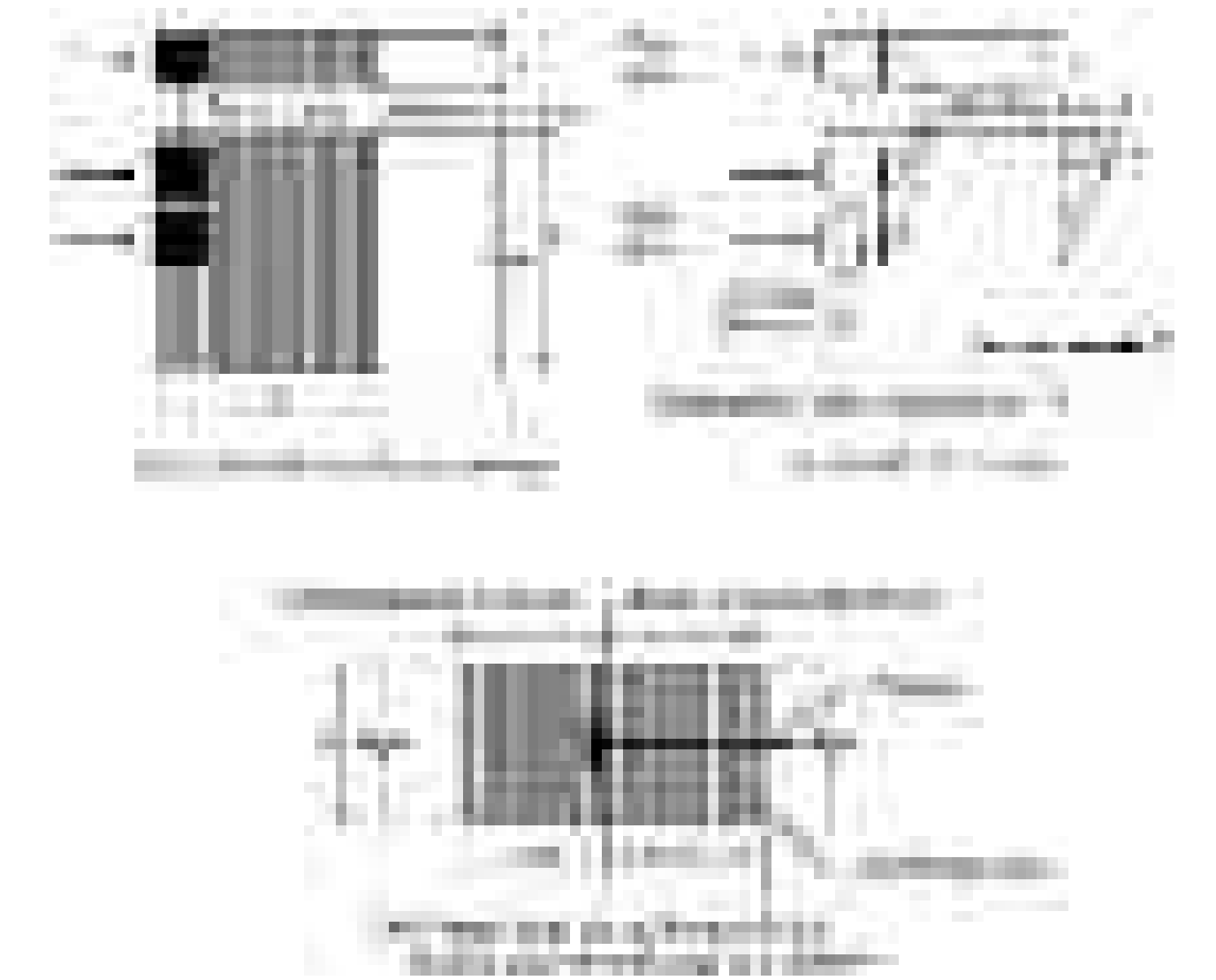
Figure 6.9.1 Anchorage zones
9.13.2 Local Zone
9.13.2.1
Design of local zones shall be based upon the factored prestressing force, and the requirements of Sections 9.9.2 (d)-(f) and 9.13.2.2.9.13.2.2
For post-tensioned anchorage zone design, a load factor of 1.2 shall be applied to the maximum steel jacking force.9.13.2.3
Local-zone reinforcement shall be provided where required for proper functioning of the anchorage device.9.13.3 General Zone
9.13.3.1
Design of general zones shall be based upon the factored prestressing force, and the requirements of Sec 9.4.14.3 b and c.9.13.3.2
General-zone reinforcement shall be provided where required to resist bursting, spalling, and longitudinal edge tension forces induced by anchorage devices. Effects of abrupt change in section shall be considered. The general zone requirements of Sec 9.13.3.2 are satisfied by Sections 9.13.4, 9.13.5, and 9.13.6 and whichever one of Sec 9.4.15.2 or Sec 9.4.15.3 or Sec 9.4.16.3 is applicable.9.13.4 Design Methods
9.13.4.1
The following methods shall be permitted for the design of the general zones of the prestressed components provided that the specific procedures used result in prediction of strength in substantial agreement with results of comprehensive tests:- (a) Equilibrium-based plasticity models (strut-and-tie models);
- (b) Linear stress analysis (including finite element analysis or equivalent); or
- (c) Simplified equations where applicable.
9.13.4.2
Simplified equations shall not be used where member cross-sections are nonrectangular, where discontinuities in or near the general zone cause deviations in the force flow path, where minimum edge distance is less than 1- 1/2 times the anchorage device lateral dimension in that direction, or where multiple anchorage devices are used in other than one closely spaced group.9.13.4.3
The stressing sequence shall be considered in the design and specified on the design drawings.9.13.4.4
Three-dimensional effects shall be considered in design and analyzed using three-dimensional procedures or approximated by considering the summation of effects for two orthogonal planes.9.13.4.5
For anchorage devices located away from the end of the member, bonded reinforcement shall be provided to transfer at least into the concrete section behind the anchor. Such reinforcement shall be placed symmetrically around the anchorage devices and shall be fully developed both behind and ahead of the anchorage devices.9.13.4.6
Where tendons are curved in the general zone, except for monostrand tendons in slabs or where analysis shows reinforcement is not required, bonded reinforcement shall be provided to resist radial and splitting forces.9.13.4.7
Except for mono-strand tendons in slabs or where analysis shows reinforcement is not required, minimum reinforcement with a nominal tensile strength equal to 2 percent of each factored prestressing force shall be provided in orthogonal directions parallel to the back face of all anchorage zones to limit spalling.9.13.4.8
Tensile strength of concrete shall be neglected in calculations of reinforcement requirements.9.13.5 Nominal Material Strengths
9.13.5.1
Tensile stress at nominal strength of bonded reinforcement is limited to for nonprestressed reinforcement and to \ for prestressed reinforcement. Tensile stress at nominal strength of unbounded prestressed reinforcement for resisting tensile forces in the anchorage zone shall be limited to \ = ! + 70.9.13.5.2
Except for concrete confined within spirals or hoops providing confinement equivalent to that corresponding to Eq. 6.9.11, compressive strength in concrete at nominal strength in the general zone shall be limited to 0.7¥gr .9.13.5.3
Concrete strength at transfer (Anchorage): Unless oversize anchorage devices are sized to compensate for the lower compressive strength or the prestressing steel is stressed to no more than 50 percent of the final prestressing force, prestressing steel shall not be stressed until compressive strength of concrete as indicated by tests consistent with the curing of the member, is at least 28 N/mm2 for multi-strand tendons or at least 17 N/mm2 for single-strand or bar tendons. Compressive strength of concrete at the time of post-tensioning shall be specified in the contract documents and in design drawings.9.13.6 Detailing Requirements
Selection of reinforcement sizes, spacing, cover, and other details for anchorage zones shall make allowances for tolerances on the bending, fabrication, and placement of reinforcement, for the size of aggregate, and for adequate placement and consolidation of the concrete.9.14 Design of Anchorage Zones For Monostrand or Single 16 Mm Diameter Bar Tendons
9.14.1 Local Zone Design
Monostrand or single 16 mm diameter or smaller diameter bar anchorage devices and local zone reinforcement shall meet the requirements of ACI 423.7 or the special anchorage device requirements of Sec 9.15.2.9.14.2 General Zone Design for Slab Tendons
9.14.2.1
For anchorage devices of 12.7 mm diameter or smaller diameter strands in normal weight concrete slabs, minimum reinforcement meeting the requirements of Sections 9.14.2.2 and 9.14.2.3 shall be provided unless a detailed analysis satisfying Sec 9.13.4 shows such reinforcement is not required.9.14.2.2
Two horizontal bars at least 12 mm diameter in size shall be provided parallel to the slab edge. They shall be permitted to be in contact with the front face of the anchorage device and shall be within a distance of h/2 ahead of each device. Those bars shall extend at least 150 mm either side of the outer edges of each device.9.14.2.3
If the center-to-center spacing of anchorage devices is 300 mm or less, the anchorage devices shall be considered as a group. For each group of six or more anchorage devices, (n+1) hairpin bars or closed stirrups at least No. 10 in size shall be provided, where n is the number of anchorage devices. One hairpin bar or stirrup shall be placed between each anchorage device and one on each side of the group. The hairpin bars or stirrups shall be placed with the legs extending into the slab perpendicular to the edge. The center portion of the hairpin bars or stirrups shall be placed perpendicular to the plane of the slab from 3h/8 to h/2 ahead of the anchorage devices.9.14.2.4
For anchorage devices not conforming to Sec 9.14.2.1, minimum reinforcement shall be based upon a detailed analysis satisfying Sec 9.13.4.9.14.3 General Zone Design for Groups of Monostrand Tendons in Beams and Girders
Design of general zones for groups of monostrand tendons in beams and girders shall meet the requirements of Sections 9.13.3 and 9.13.4.9.15 Design of Anchorage Zones For Multi-Strand Tendons
9.15.1 Local Zone Design
Basic multistrand anchorage devices and the related local and general zone reinforcement shall meet the requirements of AASHTO “LRFD Bridge Design Specifications (SI), 2007”, Articles 5.10.9.6, Approximate Stress Analysis and Design, and 5.10.9.7, Design of Local Zones. Special Anchorage Devices (AASHTO “LRFD Bridge Design Specifications (SI), 2007”, Articles 5.10.9.7.3) requires that special anchorage devices that do not satisfy the requirements specified in Sec 9.15.1, they have been tested by an independent testing agency acceptable to the Engineer and have met the acceptance criteria specified in Articles 10.3.2 and 10.3.2.3.10 of AASHTO LRFD Bridge Construction Specifications.9.15.2 Special Anchorage Devices
Where special anchorage devices are to be used, supplemental skin reinforcement shall be furnished in the corresponding regions of the anchorage zone, in addition to the confining reinforcement specified for the anchorage device. This supplemental reinforcement shall be similar in configuration and at least equivalent in volumetric ratio to any supplementary skin reinforcement used in the qualifying acceptance tests of the anchorage device.9.15.3 General Zone Design
Design for general zones for multistrand tendons shall meet the requirements of Sections 9.13.3 to 9.13.5.9.16 Cold Drawn Low Carbon Wire Prestressed Concrete (Cwpc)
9.16.1
CWPC (Cold drawn wire prestressed concrete) is termed as prestressed concrete technology of Chinese pattern. This technology is a modification of conventional prestressed concrete. In the conventional prestressed concrete high strength wire is used as reinforcement while in Chinese pattern cold drawn low carbon mild steel wire is used as such this technology is named as cold drawn wire prestressed concrete. In short it is termed as CWPC. CWPC technology is a process whereby cold drawn low carbon steel wire has been adopted as reinforcement for pre-fabricated prestressed concrete members of medium and small size as produced by pre tensioning method. On the other hand, large size structural members are produced by conventional prestressed concrete. The main features and advantages of CWPC technology can be summarized as follows:- (a) Availability (Availability of materials): The raw material of cold drawn wire is made from low carbon mild steel which can be supplied by the local mills. The tensioning process of cold-drawn wire and production of pre-cast members are also simple and very easy to handle.
- (b) Simplicity (Simplicity of equipment and devices for production): The cold process of low carbon mild steel and prefabrication process of members are done using simple equipment and devices. The precise and large sized equipment are not necessary. The production techniques of manufacturing members are rather simple.
- (c) Quality (Good in quality): The members so manufactured have high crack resistance and stiffness. After pre-tensioning no crack would occur under the service load, thus the wires within the concrete members are well protected. In contrast to conventional reinforced concrete members under the same service conditions, they have comparatively high durability to ensure long term quality.
- (d) Economy (Low cost): The cold drawn low carbon steel wire used for prestressing is made of ordinary hot-rolled carbon steel coil rod. This is processed at room temperature through a special wire drawing die. The low carbon coil rods are manufactured by the steel mills; the wires are processed at the construction site or in a prefabrication plant; or are supplied by the cold drown wire plants as readymade products. By cold drawing the low carbon rod into wires the usable strength is enhanced about twice as much as that of the coil rod. This reduces the amount of steel required in prefabricating prestressed concrete members.
- (e) Therefore, in comparison with conventional reinforced concrete reinforced with common carbon steel, a prestressed concrete member reinforced with cold drawn wire would have saving of steel consumption between 30-40%. Furthermore, since prestressed concrete members have high stiffness a reduction of cross section of members is possible. A considerable amount of concrete can also be saved and hence transportation, handling and erection work can be reduced.
- (f) Light weight (Lightness in weight): As already mentioned that the stiffness of prestressed concrete members may be enhanced, the dimension of its cross-section can be reduced correspondingly. This not only results in reduction of concrete volume but also its dead weight which is estimated as 10-30%.
9.16.2 Materials
Basically the materials used in CWPC technology are steel and concrete.- (a) Steel: steel used for CWPC is obtained by cold drawing. Cold drawing as already mentioned is a process of reducing the diameter of the coil rod by forcing it to pass through a conical die. By this process, the usable strength of steel can be increased by nearly 100%.
- (b) Concrete: The requirement of concrete in CWPC is same as that of ordinary reinforced concrete.
9.16.3 Design
Similar to other reinforced concrete structures, CWPC structures have a complete set of design specification and computational approaches by which various members of the CWPC can be designed. In the design of prestressed members the function of pre-stressing force and pre-stressing losses should be calculated. CWPC members should be checked for its strength, stability and cracking resistance respectively at different stages including service, manufacturing, handling, erection and construction. In designing members conformity to local specifications should be considered. Cold drawn low carbon wire conforming to ASTM A615 or equivalent may be permitted for prestressing provided the mechanical requirements shown in Table 6.9.5 are satisfied. Table 6.9.5: Tensile Strength and Elongation of Cold Drawn Wire9.17 External Post-Tensioning
9.17.1
Post-tensioning tendons shall be permitted to be external to any concrete section of a member. The strength and serviceability design methods of this Code shall be used in evaluating the effects of external tendon forces on the concrete structure.9.17.2
External tendons shall be considered as unbonded tendons when computing flexural strength unless provisions are made to effectively bond the external tendons to the concrete section along its entire length.9.17.3
External tendons shall be attached to the concrete member in a manner that maintains the desired eccentricity between the tendons and the concrete centroid throughout the full range of anticipated member deflection.9.17.4
External tendons and tendon anchorage regions shall be protected against corrosion, and the details of the protection method shall be indicated on the drawings or in the project specifications.9.18 Performance Requirement Of Prestressed Concrete Design
9.18.1 Classification of Performance Requirement
After the outline of the member dimensions are determined and the most suitable kind and type of prestressing options are selected at the structural planning stage, the prestressed concrete non-composite and composite structures and members shall satisfy all of the required performances such as safety, serviceability, restorability, durability, reparability, societal and environmental compatibility, etc. at every stage of design, construction and maintenance throughout the design life of the structure. Table 6.9.6 gives the performance requirement of prestressed concrete structures and components and related performance items. Table 6.9.6: Classification of Performance Requirement for Prestressed Concrete Structures9.18.2 Performance Verification Method
- (a) Performance verification shall be based on the partial factor method on the basis of reliability theory and as a standard design procedure, it shall be based on the limit state method.
- (b) In general verification shall be based on design responses to design actions, design limits as determined by design material strengths, and individual partial factors. The performance of the structure shall, in general, be verified using Equations 6.9.13 and 6.9.14:
- (c) During design, a verification shall be carried out for every limit state that can be considered.
- (d) The flow chart explaining the concept of verification of safety is given in Figure 6.9.2.
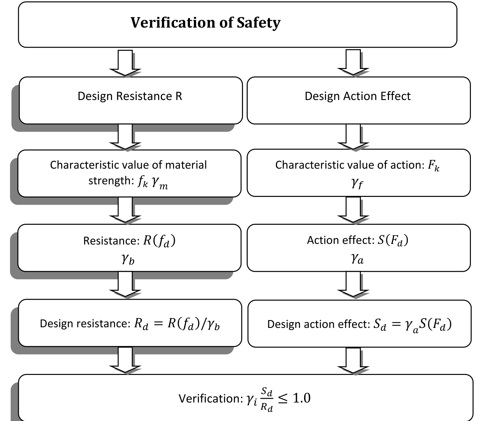
Figure 6.9.2 Flow chart explaining the concept of verification of safety
9.18.3 Partial Factors
- (a) Partial factors shall be determined on the concept given (i) and (ii) below.
- (i) The material factor, structural member factor, structural analysis factor, and action factor shall be determined in consideration of
- unfavorable deviations from characteristic values,
- uncertainties in computational accuracy, and
- discrepancies between design and practice with respect to actions or structures and materials.
- Table 6.9.7 shows the standard values of partial factors.
- (ii) The structural factor ¡g shall be determined according to structural importance and also the social and economic impact of the structure reaching its limit state.
9.19 Materials
9.19.1 Concrete Ingredients and Applicable ASTM Standards
Table 6.9.9 shows the list of commonly applicable standards for cement, coarse and fine aggregates, admixtures and mixing water. Table 6.9.9: Applicable Standards for Cement, Coarse and Fine Aggregates, Admixtures and Water9.19.2 Reinforcing Steel and Applicable Standards
Table 6.9.10 shows the types of reinforcing steel with the ASTM and BDS Designation standard specifications. Table 6.9.10: List of Standards for the Reinforcing Steel9.19.3 Prestressing Steel and Applicable ASTM Standards
Table 6.9.11 shows the types of high tensile prestressing steel and cold drawn wires used for prestressing, with the ASTM Designation standard specifications. Table 6.9.11: List of Standards for the Prestressing Steel9.20 Construction of Prestressed Concrete Structures
9.20.1 Corrosion Protection for Unbonded Tendons
9.20.1.1
Unbonded prestressing steel shall be encased with sheathing. The prestressing steel shall be completely coated and the sheathing around the prestressing steel filled with suitable material to inhibit corrosion.9.20.1.2
Sheathing shall be watertight and continuous over entire length to be unbonded.9.20.1.3
For applications in corrosive environments, the sheathing shall be connected to all stressing, intermediate and fixed anchorages in a water tight fashion.9.20.1.4
Unbonded single-strand tendons shall be protected against corrosion in accordance with ACI 423.7.9.20.2 Post-tensioning Ducts
9.20.2.1
Ducts for grouted tendons shall be mortar- tight and nonreactive with concrete, prestressing steel, grout, and corrosion inhibitor.9.20.2.2
Ducts for grouted single-wire, single-strand, or single-bar tendons shall have an inside diameter at least 6 mm larger than the prestressing steel diameter.9.20.2.3
Ducts for grouted multiple wire, multiple strand, or multiple bar tendons shall have an inside cross-sectional area at least two times the crosssectional area of the prestressing steel.9.20.2.4
Ducts shall be maintained free of ponded water if members to be grouted are exposed to temperatures below freezing prior to grouting.9.20.3 Grout for Bonded Tendons
9.20.3.1
Grout shall consist of Portland cement and water; or Portland cement, sand, and water.9.20.3.2
Materials for grout shall conform to Sections 9.20.3.3 to 9.20.3.5.9.20.3.3
Portland cement shall conform to Sec 9.19.1.9.20.3.4
Water shall conform to Sec 9.19.1.9.20.3.5
Sand, if used, shall conform to Sec 9.19.1 except that gradation shall be permitted to be modified as necessary to obtain satisfactory workability.9.20.3.6
Admixtures conforming to Sec 9.19.1 and known to have no injurious effects on grout, steel, or concrete shall be permitted. Calcium chloride shall not be used.9.20.4 Selection of Grout Proportions
9.20.4.1
Proportions of materials for grout shall be based on either (a) or (b) below.- (a) Results of tests on fresh and hardened grout prior to beginning grouting operations; or
- (b) Prior documented experience with similar materials and equipment and under comparable field conditions.
9.20.4.2
Cement used in the Work shall correspond to that on which selection of grout proportions was based.9.20.4.3
Water content shall be minimum necessary for proper pumping of grout; however, water-cement ratio shall not exceed 0.45 by weight.9.20.4.4
Water shall not be added to increase grout flowability that has been decreased by delayed use of the grout.9.20.5 Mixing and Pumping of Grout
9.20.5.1
Grout shall be mixed in equipment capable of continuous mechanical mixing and agitation that will produce uniform distribution of materials, passed through screens, and pumped in a manner that will completely fill the ducts.9.20.5.2
Temperature of members at time of grouting shall be above 2°C and shall be maintained above 2°C until field-cured 50 mm cubes of grout reach a minimum compressive strength of 5.5 N/mm2 .9.20.5.3
Grout temperatures shall not be above 32°C during mixing and pumping.9.20.6 Protection for Prestressing Steel During Welding
Burning or welding operations in the vicinity of prestressing steel shall be performed so that prestressing steel is not subject to excessive temperatures, welding sparks, or ground currents.9.20.7 Application and Measurement of Prestressing Force
9.20.7.1
Prestressing force shall be determined by both of (a) and (b):- (a) Measurement of steel elongation. Required elongation shall be determined from average load-elongation curves for the prestressing steel used;
- (b) Observation of jacking force on a calibrated gage or load cell or by use of a calibrated dynamometer.
9.20.7.2
Where the transfer of force from the bulk- heads of pretensioning bed to the concrete is accomplished by flame cutting prestressing steel, cutting points and cutting sequence shall be predetermined to avoid undesired temporary stresses.9.20.7.3
Long lengths of exposed pretensioned strand shall be cut near the member to minimize shock to concrete.9.20.7.4
Total loss of prestress due to unreplaced broken prestressing steel shall not exceed 2 percent of total prestress.9.20.8 Post-tensioning Anchorages and Couplers
9.20.8.1
Anchorages and couplers for bonded and unbonded tendons shall develop at least 95 percent of the when tested in an unbonded condition, without exceeding anticipated set. For bonded tendons, anchorages and couplers shall be located so that 100 percent of shall be developed at critical sections after the prestressing steel is bonded in the member.9.20.8.2
Couplers shall be placed in areas approved by the licensed design professional and enclosed in housing long enough to permit necessary movements.9.20.8.3
In unbonded construction subject to repetitive loads, attention shall be given to the possibility of fatigue in anchorages and couplers.9.20.8.4
Anchorages, couplers, and end fittings shall be permanently protected against corrosion.9.21 Performance Requirement of Material
9.21.1
The fundamental performance requirement of materials forming the structure is that they should be able to resist actions such as the various loadings to which the structure is exposed.9.21.2
Materials forming the structure should not reach unexpected limit states as a result of deterioration phenomena during the working life of the structure.9.21.3
Materials-related energy consumption and CO2 discharges should be minimized, while recyclability should be high. Any materials that escape into the surrounding environment during construction and service should not have a strong impact on human beings, animals and plants. Commentary: Corresponding to design requirements, the materials should be evaluated to ensure that their properties are suitable with respect to strength (tensile, compressive and shear), deformation (e.g. elastic modulus), heat resistance and water tightness. The characteristic values obtained from the tests, complying appropriate BDS, ASTM, BS, or equivalent standards, on such specimens should be converted to suit the design calculation models using appropriate conversion factors or functions. The characteristic value of material strength is calculated from test results using Eq. 6.9.15. Where, : mean of test values, : standard deviation of test values, and : coefficient of variance. The coefficient k is determined from the probability of obtaining a test value less than the characteristic value and the probability distribution of test results. The 5% fractile value is often taken as the characteristic value. In this case, the value of k is 1.64 if the normal distribution is assumed for the test values. At the structural design stage, verification shall be performed so that response value is less than or equal to the limit value of performance throughout both construction period and working life. At the end of construction stage, just completed structure shall fulfill the all required performances considered in its design. Division C : Maintenance (Sections 9.22 To 9.27)9.22 General
If the prestressed concrete structure is designed and constructed in accordance with the appropriate concepts described in Part I and II of this Chapter, based on which the durability is checked by verifying the performance requirements of the concrete and its constituent materials, it is not likely that structural deterioration would become so significant as to degrade the performance of the structure. On the other hand it is not easy to estimate the performance degradation process of the structure during its service life accurately. Also, it is difficult to completely avoid construction defects at all construction stages. Therefore, the new structure should be appropriately maintained by routine and regular inspections, based on an adequate maintenance plan formulated at the design stage. For existing structures, deterioration may be evident in some cases, with the performance having been degraded. The defects of such structures should be accurately assessed and identified as initial defects, damage, or deteriorations. Major causes for such defects should be identified subsequently so that appropriate remedial actions can be selected. The initial defects and damage should be treated promptly and appropriately including emergency treatments. When the deterioration that would degrade the performance is evident, the deterioration mechanisms should be identified and appropriate maintenance, carried out based on the results of deterioration prediction and performance degradation evaluation.9.23 Classification of Maintenance Action
Maintenance actions shall be classified into different categories depending on such factors as the importance of the structure, design life, impact on a third party, environmental conditions, ease of maintenance, and cost. In the view of the above, four categories are recommended for the classifications of the maintenance actions:9.23.1 Category A : Preventive Maintenance
Maintenance to prevent deterioration which would otherwise lead to unsatisfactory structural performance. Category A structures are those- for which remedial actions are difficult to take after deterioration becomes apparent;
- of which deterioration must not be apparent;
- having a long design life.
9.23.2 Category B : Corrective Maintenance
Maintenance to restore the performance level and/or to reduce the rate of deterioration so as to maintain satisfactory structural performance. Category B structures are those for which- remedial measures can be taken after deterioration becomes apparent;
- apparent deterioration causes no appreciable inconvenience.
9.23.3 Category C : Observational Maintenance
Maintenance in which visual inspection is necessary without any remedial action regardless of the deterioration level. Category C structures are those- for use as long as they are usable;
- for which ensuring safety from threats posed to third parties is the only requirement.
9.23.4 Category D : Indirect Maintenance
Maintenance in which no direct inspection is necessary or possible. Category D structures are those for which direct inspection is extremely difficult. For these reasons, non-inspection maintenance after the initial inspection is carried out not as routine or regular inspection, but as extraordinary inspection following natural disasters, accidents, etc.9.24 Maintenance Record
Records, drawings and related documents prepared during the time of planning, design and construction shall be referred to and made use of while developing an appropriate methodology for maintenance covering inspection and repairs. Commentary: A thorough study of the planning, design and construction related documents often provide insights into the inherent weaknesses of the structure which in turn often serve as pointers for further detailed inspection and/or repairs. Furthermore, a clear record should be kept of the difficulties encountered, remedial actions taken and any deviation from the design drawings. These record also serve as a valuable reference in the design and construction of similar structures and their subsequent inspections.9.25 Inspection
9.25.1 General
On the basis of the methods used in the frequency and timing, inspection shall be classified as initial inspection, routine inspection, regular inspection, detailed inspection, extraordinary inspection, and monitoring.9.25.2 Initial Inspection
Initial inspection is intended to examine whether the structure is adequately constructed. It also allows the collection of basic data for initiating a maintenance program. Initial inspection shall also be carried out just after the completion of remedial actions. Initial inspection should cover the external appearance of the structure, variation of concrete quality, existence of construction defects, construction errors on reinforcing and pretsressing bar arrangement, and so on.9.25.3 Routine Inspections
It shall be carried out on a routine basis at certain intervals without making any specific effort to identify signs of deterioration, if any, and the time of their first appearance. The exact tools to be used and the frequency of such inspections may be decided on the basis of such factors as the likely mechanisms of such deterioration, environmental conditions, importance of the structure, and the maintenance action classification. A routine inspection should cover the external appearance of the structure including cracks, spalling, delamination, color changes, rust stain from reinforcement, and isolation of free lime from concrete.9.25.4 Regular Inspection
It shall be carried out at regular intervals using appropriate tools to identify signs of deterioration and the time of their first appearance. Efforts shall be made during a regular inspection to observe the structure closely to obtain details which will be difficult to gather during a routine inspection. Visual inspection and/or hammering inspection are carried out mainly to obtain more details on the items inspected in a routine inspection. In addition, inspections by using appropriate non-destructive tests or taking concrete cores etc. can be effectively combined with the visual inspection.9.25.5 Detailed Inspection
Detailed inspection shall be done when- (a) some signs of deterioration or a change in the performance level are observed during a routine and/or regular inspection;
- (b) it is difficult to obtain reliable and accurate information during a routine and/or regular inspection;
- (c) it is found that the structural integrity of the structure has been adversely affected by the extent of the deterioration;
- (d) more detailed information is required before deciding on the necessity and scope for undertaking a major repair, rehabilitation or strengthening work.
9.25.6 Extraordinary Inspection
It shall be carried out after a structure has been subjected to an accidental load to assess the extent of the damage and the need for remedial actions. Such accidental loads may include those caused by an earthquake, storm, flood, fire, explosion, etc.9.26 Monitoring
The deterioration and/or performance of the concerned structure as determined in 9.6.2, shall be monitored, through continuous recording of the appropriate data, together with routine and regular inspections, so that the appropriate remedial actions can be taken before the deterioration becomes detrimental to the appearance and other performance of the structure.9.26.1 Deterioration Mechanism and Prediction
9.26.1.1 General
The prevailing state of the concerned structure shall be evaluated as properly as possible according to the inspection results, design and construction records, environmental conditions, and any other relevant information. Then when any deterioration is found, the possible causes of the deterioration and the corresponding mechanism can be appropriately estimated.9.26.1.2 Identification of deterioration mechanisms
Deterioration of a structure is caused by the environmental actions and loading conditions. Environment-oriented deterioration includes carbonation-induced deterioration, chloride-induced deterioration, chemical attack, alkali-aggregate reaction, etc. On the other hand external force-oriented deterioration includes fatigue, excessive loading, and differential settlement of the support.9.26.1.3 Deterioration factors
Deterioration factors may be classified into those- (a) external to structures such as temperature, humidity and any other environmental characteristics; and
- (b) internal to the structure such as design parameters and quality control during construction.
9.26.1.4 Determination of deterioration levels and rates
The level of deterioration and/or performance shall be determined based on the results of inspections and simulations using appropriate models for the mechanisms of deterioration. The following features appearing on the surface of the structure may be used for evaluating the degree of deterioration and the level of performance:- (a) crack pattern, length and width;
- (b) the extent of delamination, peeling and spalling of concrete cover, and scaling and degradation areas;
- (c) abnormal hammer tapping sound and the extent of abnormality;
- (d) presence and degree of exudation of rust and efflorescence and water leakage.
9.26.2 Evaluation and Decision Making
9.26.2.1 General
In general, the deterioration and performance degradation of a structure progress monotonically. The decision, therefore, should be made based on the evaluation outcome of the performance of the structure at the time of inspection and at the end of its design life.9.26.2.2 Threshold level
The threshold level of the structure’s degraded performance shall be specified in accordance with the requirements of safety, functionality, appearance, societal friendliness and such other factors, taking into consideration the type, importance and maintenance level of the structure and the environmental conditions.9.26.2.3 Evaluation of inspection results
The results from routine and regular inspections shall be evaluated and a decision shall be made whether a detailed inspection is required or otherwise. The results from the detailed and/or extraordinary inspections shall be evaluated and a decision shall be made whether a remedial action is required or otherwise. Immediate remedial actions shall be taken in cases where deterioration, damage and/or initial defects are found to be hazardous to third parties.9.27 Remedial Action
9.27.1 General
A remedial action on a deteriorated structure shall be taken on the basis of the inspection results, importance of the structure, maintenance classification, and the threshold level of deterioration and/or performance. Commentary: Repair and strengthening are the main techniques of remedial actions of which details are described in Sections 9.2.7.3 and 9.2.7.4 respectively. The following measures are also included in the remedial actions. Intensified inspection: inspection may be carried out by suitably increasing one or more of the following: frequency of inspection, number of inspection items, and the locations for inspection. Usage restriction: suitable restriction shall be imposed on the maximum live load that the structure may carry, depending on the level of deterioration observed. Functional improvement or restoration: this may include an appearance improvement that beautifies a structure with suitably painting or placing additional concrete, and so on. Dismantling and removal: in a case when the deterioration of a structure is too severe for its structural performance to be sufficiently restored, and dismantling or the removal is one of the choices as the remedial measures. Special care for emergency: when a deteriorated structure poses an immediate threat to the environment, its users, or third parties, suitable emergency action shall be taken immediately.9.27.2 Selection of Remedial Action
Selection of methods and materials suitable for the relevant deterioration mechanism and degree of performance degradation is particularly important for measures for which wide varieties of methods and materials are available. Care should be taken as the method of restoring the performance may vary depending on the deterioration mechanism, even if the level of performance is the same.9.27.3 Repair
9.27.3.1 General
Repair of a structure refers to the remedial action taken to prevent or slow down its further deterioration and reduce the possibility of damage to its users or third parties. Types of repair include (i) repair of defects such as cracking and peeling; (ii) removal of concrete damaged by deterioration due to carbonation and such like; (iii) surface coating to prevent re-intrusion of hazardous substances.9.27.3.2 Preparation and execution
A complete plan for the repair work including methods of repair, materials to be used, and tests to ensure the quality of work, shall be developed before the repair work commences. Repair works shall be carried out with minimum disturbances to the surrounding environment. Necessary tests to ensure the quality of the repair work shall be carried out. Detailed record of the repair work shall be maintained for future reference.9.27.3.3 Methods and materials
Some current repair methods and associated materials are- crack repair by injecting epoxy;
- section repair including patching using polymer cement mortar;
- surface protection by resin or mortar;
- cathodic protection;
- re-alkalization;
- de-salination, wherever required.
9.27.4 Strengthening
9.27.4.1 General
Strengthening of a structure refers to the remedial action taken to restore or improve its structural properties including load carrying capacity and stiffness, to a level which is equal to or higher than that of the original design. Commentary: Strengthening methods include (i) replacement of members; (ii) an increase in the cross-sectional area of concrete; (iii) addition of members; (iv) an increase of the support points; (v) addition of strengthening members; (vi) external prestressing, etc.9.27.4.2 Preparation and execution
Strengthening of a structure shall be preceded by a thorough investigation of its deterioration considering such factors as the remaining design life, deterioration mechanism, possible causes and extent of deterioration, the remaining and desired load-carrying capacity or stiffness, importance of the structure, maintenance classification, and any remedial actions taken previously. A complete plan for the strengthening work including design calculations, methods of strengthening, materials to be used, and tests to ensure quality of the work, shall be developed before work commences. Strengthening work shall be carried out with minimum disturbance to the surrounding environment and the service condition of the structure.9.27.4.3 Methods and materials
Some current methods and associated materials for strengthening are- external bonding viz plate or sheet bonding and over or under-laying using steel or carbon sheets;
- external prestressing using additional tension cables;
- addition of girders, braces and/or supports;
- replacement of members;
- seismic isolation.