
2.1 Introduction
2.1.1 Scope
This Chapter specifies the minimum design forces including dead load, live load, wind and earthquake loads, miscellaneous loads and their various combinations. These loads shall be applicable for the design of buildings and structures in conformance with the general design requirements provided in Chapter 1.2.1.2 Limitations
Provisions of this Chapter shall generally be applied to majority of buildings and other structures covered in this Code subject to normally expected loading conditions. For those buildings and structures having unusual geometrical shapes, response characteristics or site locations, or for those subject to special loading including tornadoes, special dynamic or hydrodynamic loads etc., site-specific or case-specific data or analysis may be required to determine the design loads on them. In such cases, and all other cases for which loads are not specified in this Chapter, loading information may be obtained from reliable references or specialist advice may be sought. However, such loads shall be applied in compliance with the provisions of other Parts or Sections of this Code.2.1.3 Terminology
The following definitions apply only to the provisions of this Chapter: ALLOWABLE A method for proportioning structural members such that STRESS DESIGN the maximum stresses due to service loads obtained from an METHOD (ASD) elastic analysis does not exceed a specified allowable value. This is also called Working Stress Design Method (WSD). APPROVED Acceptable to the authority having jurisdiction. BASE The level at which the earthquake motions are considered to be imparted to the structures or the level at which the structure as a dynamic vibrator is supported. BASE SHEAR Total design lateral force or shear due to earthquake at the base of a structure.2.1.4 Symbols and Notation
The following symbols and notation apply only to the provisions of this Chapter:- = Effective wind area, in m2
- = Area of open buildings and other structures either normal to the wind direction or projected on a plane normal to the wind direction, in m2.
- = Gross area of that wall in which is identified, in m2.
- = Sum of gross surface areas of the building envelope (walls and roof) not including , in m2
- = Total area of openings in a wall that receives positive external pressure, in m2.
- = Sum of the areas of openings in the building envelope (walls and roof) not including , in m2
- = Total area of openings in the building envelope in m2
- = Gross area of the solid freestanding wall or solid sign, in m2
- = Torsion amplification factor at level-.
- = Horizontal dimension of building measured normal to wind direction, in m.
- = Deflection amplification factor.
- = Force coefficient to be used in determination of wind loads for other structures
- = Net pressure coefficient to be used in determination of wind loads for open buildings
- = External pressure coefficient to be used in determination of wind loads for buildings
- = Normalized acceleration response spectrum.
- = Numerical coefficient to determine building period
- = Diameter of a circular structure or member in m (as used in Sec 2.4).
- = Dead loads, or related internal moments and forces, Dead load consists of: a) weight of the member itself, b) weight of all materials of construction incorporated into the building to be permanently supported by the member, including built-in partitions, c) weight of permanent equipment (as used in Sec 2.7).
2.2 Dead Loads
2.2.1 General
The minimum design dead load for buildings and portions thereof shall be determined in accordance with the provisions of this Section. In addition, design of the overall structure and its primary load-resisting systems shall conform to the general design provisions given in Chapter 1.2.2.2 Definition
Dead Load is the vertical load due to the weight of permanent structural and nonstructural components and attachments of a building such as walls, floors, ceilings, permanent partitions and fixed service equipment etc.2.2.3 Assessment of Dead Load
Dead load for a structural member shall be assessed based on the forces due to:- weight of the member itself,
- weight of all materials of construction incorporated into the building to be supported permanently by the member,
- weight of permanent partitions,
- weight of fixed service equipment, and
- net effect of prestressing.
2.2.4 Weight of Materials and Constructions
In estimating dead loads, the actual weights of materials and constructions shall be used, provided that in the absence of definite information, the weights given in Tables 6.2.1 and 6.2.2 shall be assumed for the purposes of design. Table 6.2.1: Unit Weight of Basic Materials- for reinforced concrete, add 0.63 kN/m3 for each 1% by volume of main reinforcement
- For brick aggregate, 90% of the listed values may be used.
2.2.5 Weight of Permanent Partitions
When partition walls are indicated on the plans, their weight shall be considered as dead load acting as concentrated line loads in their actual positions on the floor. The loads due to anticipated partition walls, which are not indicated on the plans, shall be treated as live loads and determined in accordance with Sec 2.3.6.2.2.6 Weight of Fixed Service Equipment
Weights of fixed service equipment and other permanent machinery, such as electrical feeders and other machinery, heating, ventilating and air-conditioning systems, lifts and escalators, plumbing stacks and risers etc. shall be included as dead load whenever such equipment are supported by structural members.2.2.7 Additional Loads
In evaluating the final dead loads on a structural member for design purposes, allowances shall be made for additional loads resulting from the (i) difference between the prescribed and the actual weights of the members and construction materials; (ii) inclusion of future installations; (iii) changes in occupancy or use of buildings; and (iv) inclusion of structural and non-structural members not covered in Sections 2.2.2 and 2.2.3.2.3 Live Loads
2.3.1 General
The live loads used for the structural design of floors, roof and the supporting members shall be the greatest applied loads arising from the intended use or occupancy of the building, or from the stacking of materials and the use of equipment and propping during construction, but shall not be less than the minimum design live loads set out by the provisions of this Section. For the design of structural members for forces including live loads, requirements of the relevant Sections of Chapter 1 shall also be fulfilled.2.3.2 Definition
Live load is the load superimposed by the use or occupancy of the building not including the environmental loads such as wind load, rain load, earthquake load or dead load.2.3.3 Minimum Floor Live Loads
The minimum floor live loads shall be the greatest actual imposed loads resulting from the intended use or occupancy of the floor, and shall not be less than the uniformly distributed load patterns specified in Sec 2.3.4 or the concentrated loads specified in Sec 2.3.5 whichever produces the most critical effect. The live loads shall be assumed to act vertically upon the area projected on a horizontal plane.2.3.4 Uniformly Distributed Loads
The uniformly distributed live load shall not be less than the values listed in Table 6.2.3, reduced as may be specified in Sec 2.3.13, applied uniformly over the entire area of the floor, or any portion thereof to produce the most adverse effects in the member concerned.2.3.5 Concentrated Loads
The concentrated load to be applied non-concurrently with the uniformly distributed load given in Sec 2.3.4, shall not be less than that listed in Table 6.2.3. Unless otherwise specified in Table 6.2.3 or in the following paragraph, the concentrated load shall be applied over an area of 300 mm × 300 mm and shall be located so as to produce the maximum stress conditions in the structural members. In areas where vehicles are used or stored, such as car parking garages, ramps, repair shops etc., provision shall be made for concentrated loads consisting of two or more loads spaced nominally 1.5 m on centres in absence of the uniform live loads. Each load shall be 40 percent of the gross weight of the maximum size vehicle to be accommodated and applied over an area of 750 mm × 750 mm. For the storage of private or pleasure-type vehicles without repair or fuelling, floors shall be investigated in the absence of the uniform live load, for a minimum concentrated wheel load of 9 kN spaced 1.5 m on centres, applied over an area of 750 mm × 750 mm. The uniform live loads for these cases are provided in Table 6.2.3. The condition of concentrated or uniform live load producing the greater stresses shall govern. Table 6.2.3: Minimum Uniformly Distributed and Concentrated Live Loadsa- a It must be ensured that the average weight of equipment, machinery, raw materials and products that may occupy the floor is less than the specified value in the Table. In case the weight exceeds the specified values in the Table, actual maximum probable weight acting in the actual manner shall be used in the analysis and design.
- b Floors in garages or portions of a building used for the storage of motor vehicles shall be designed for the uniformly distributed live loads of Table 6.2.3 or the following concentrated load: (1) for garages restricted to passenger vehicles accommodating not more than nine passengers, 13.35 kN acting on an area of 114 mm by 114 mm footprint of a jack; and (2) for mechanical parking structures without slab or deck that are used for storing passenger car only, 10 kN per wheel.
- c Garages accommodating trucks and buses shall be designed in accordance with an approved method, which contains provisions for truck and bus loadings.
- d The loading applies to stack room floors that support non-mobile, double-faced library book stacks subject to the following limitations: (1) The nominal book stack unit height shall not exceed 2290 mm; (2) the nominal shelf depth shall not exceed 300 mm for each face; (3) parallel rows of double-faced book stacks shall be separated by aisles not less than 900 mm wide.
- e Subject to the provisions of reduction of live load as per Sec 2.3.13
- f Uniformly distributed and concentrated load provisions are applicable for a maximum floor height of 3.5 m. In case of higher floor height, the load(s) must be proportionally increased.
- g In addition to the vertical live loads, the design shall include horizontal swaying forces applied to each row of the seats as follows: 0.350 kN per linear meter of seat applied in a direction parallel to each row of seats and 0.15 kN per linear meter of seat applied in a direction perpendicular to each row of seats. The parallel and perpendicular horizontal swaying forces need not be applied simultaneously.
- h Where uniform roof live loads are reduced to less than 1.0 kN/m2 in accordance with Sec 2.3.14.1 and are applied to the design of structural members arranged so as to create continuity, the reduced roof live load shall be applied to adjacent spans or to alternate spans, whichever produces the greatest unfavorable effect.
- i Roofs used for other special purposes shall be designed for appropriate loads as approved by the authority having jurisdiction.
- j Other uniform loads in accordance with an approved method, which contains provisions for truck loadings, shall also be considered where appropriate.
- k The concentrated wheel load shall be applied on an area of 114 mm by 114 mm footprint of a jack.
- l Minimum concentrated load on stair treads (on area of 2,580 mm2 ) is 1.33 kN.
- The loading in industrial buildings varies considerably and so the loadings under the terms ‘light,’ ‘medium’ and ‘heavy’ are introduced in order to allow for which the relevant floor is designed. It is however important to assess the actual loads to ensure that they are not in excess of the stipulated load, in case where they are in excess, the design shall be based on the actual loadings.
2.3.6 Provision for Partition Walls
When partitions, not indicated on the plans, are anticipated to be placed on the floors, their weight shall be included as an additional live load acting as concentrated line loads in an arrangement producing the most severe effect on the floor, unless it can be shown that a more favourable arrangement of the partitions shall prevail during the future use of the floor. In the case of light partitions, wherein the total weight per metre run is not greater than 5.5 kN, a uniformly distributed live load may be applied on the floor in lieu of the concentrated line loads specified above. Such uniform live load per square metre shall be at least 33% of the weight per metre run of the partitions, subject to a minimum of 1.2 kN/m2 .2.3.7 More than One Occupancy
Where an area of a floor is intended for two or more occupancies at different times, the value to be used from Table 6.2.3 shall be the greatest value for any of the occupancies concerned.2.3.8 Minimum Roof Live Loads
Roof live loads shall be assumed to act vertically over the area projected by the roof or any portion of it upon a horizontal plane, and shall be determined as specified in Table 6.2.4. Table 6.2.4: Minimum Roof Live Loads(1 )- Note: (1) Greater of this load and rain load as specified in Sec 2.6.2 shall be taken as the design live load for roof. The distributed load shall be applied over the area of the roof projected upon a horizontal plane and shall not be applied simultaneously with the concentrated load. The concentrated load shall be assumed to act upon a 300 mm × 300 mm area and need not be considered for roofs capable of laterally distributing the load, e.g. reinforced concrete slabs.
2.3.9 Loads not Specified
Live loads, not specified for uses or occupancies in Sections 2.3.3, 2.3.4 and 2.3.5, shall be determined from loads resulting from:- (a) weight of the probable assembly of persons;
- (b) weight of the probable accumulation of equipment and furniture, and
- (c) weight of the probable storage of materials.
2.3.10 Partial Loading and Other Loading Arrangements
The full intensity of the appropriately reduced live load applied only to a portion of the length or area of a structure or member shall be considered, if it produces a more unfavourable effect than the same intensity applied over the full length or area of the structure or member. Where uniformly distributed live loads are used in the design of continuous members and their supports, consideration shall be given to full dead load on all spans in combination with full live loads on adjacent spans and on alternate spans whichever produces a more unfavourable effect.2.3.11 Other Live Loads
Live loads on miscellaneous structures and components, such as handrails and supporting members, parapets and balustrades, ceilings, skylights and supports, and the like, shall be determined from the analysis of the actual loads on them, but shall not be less than those given in Table 6.2.5.2.3.12 Impact and Dynamic Loads
The live loads specified in Sec 2.3.3 shall be assumed to include allowances for impacts arising from normal uses only. However, forces imposed by unusual vibrations and impacts resulting from the operation of installed machinery and equipment shall be determined separately and treated as additional live loads. Live loads due to vibration or impact shall be determined by dynamic analysis of the supporting member or structure including foundations, or from the recommended values supplied by the manufacture of the particular equipment or machinery. In absence of definite information, values listed in Table 6.2.6 for some common equipment, shall be used for design purposes. Table 6.2.5: Miscellaneous Live Loads- Notes: (1) These loads shall be applied non-concurrently along horizontal and vertical directions, except as specified in note (2) below.
- (2) These loads shall be applied only in the horizontal direction, uniformly distributed over any length of 1.5 m of a barrier and shall be considered to act at bumper height. For case 2(a) bumper height may be taken as 375 mm above floor level.
- (3) Barriers to access ramps of car parks shall be designed for horizontal forces equal to 50% of those given in 2(a) and 2(b) applied at a level of 610 mm above the ramp. Barriers to straight exit ramps exceeding 20 m in length shall be designed for horizontal forces equal to twice the values given in 2(a) and 2(b).
2.3.13 Reduction of Live Loads
Except for roof uniform live loads, all other minimum uniformly distributed live loads, Lo in Table 6.2.3, may be reduced according to the following provisions.2.3.13.1 General
Subject to the limitations of Sections 2.3.13.2 to 2.3.13.5, members for which a value of is 37.16 m2 or more are permitted to be designed for a reduced live load in accordance with the following formula: Where, L = reduced design live load per m2 of area supported by the member; L0 = unreduced design live load per m2 of area supported by the member (Table 6.2.3); KLL = live load element factor (Table 6.2.7); AT = tributary area in m2 , L shall not be less than 0.50 L0 for members supporting one floor and L shall not be less than 0.40 L0 for members supporting two or more floors. Table 6.2.7: Live Load Element Factor,- *In lieu of the preceding values, is permitted to be calculated.
2.3.13.2 Heavy live loads
Live loads that exceed 4.80 kN/m2 shall not be reduced. Exception: Live loads for members supporting two or more floors may be reduced by 20 percent.2.3.13.3 Passenger car garages
The live loads shall not be reduced in passenger car garages. Exception: Live loads for members supporting two or more floors may be reduced by 20 percent.2.3.13.4 Special occupancies
- (a) Live loads of 4.80 kN/m2 or less shall not be reduced in public assembly occupancies.
- (b) There shall be no reduction of live loads for cyclone shelters.
2.3.13.5 Limitations on one-way slabs
The tributary area, AT , for one-way slabs shall not exceed an area defined by the slab span times a width normal to the span of 1.5 times the slab span.2.3.14 Reduction in Roof Live Loads
The minimum uniformly distributed roof live loads, Lo in Table 6.2.3, are permitted to be reduced according to the following provisions.2.3.14.1 Flat, pitched, and curved roofs.
Ordinary flat, pitched, and curved roofs are permitted to be designed for a reduced roof live load, as specified in Eq. 6.2.2 or other controlling combinations of loads, as discussed later in this Chapter, whichever produces the greater load. In structures such as greenhouses, where special scaffolding is used as a work surface for workmen and materials during maintenance and repair operations, a lower roof load than specified in Eq. 6.2.2 shall not be used unless approved by the authority having jurisdiction. On such structures, the minimum roof live load shall be 0.60 kN/m2 . Where,- reduced roof live load per m2 of horizontal projection in kN/m2
- tributary area in m2 supported by any structural member and
2.3.14.2 Special purpose roofs.
Roofs that have an occupancy function, such as roof gardens, assembly purposes, or other special purposes are permitted to have their uniformly distributed live load reduced in accordance with the requirements of Sec 2.3.13.2.4 Wind Loads
2.4.1 General
Scope: Buildings and other structures, including the Main Wind-Force Resisting System (MWFRS) and all components and cladding thereof, shall be designed and constructed to resist wind loads as specified herein. Allowed Procedures: The design wind loads for buildings and other structures, including the MWFRS and component and cladding elements thereof, shall be determined using one of the following procedures:- Method 1: Simplified Procedure as specified in Sec 2.4.2 for buildings and structures meeting the requirements specified therein;
- Method 2: Analytical Procedure as specified in Sec 2.4.3 for buildings and structures meeting the requirements specified therein;
- Method 3: Wind Tunnel Procedure as specified in Sec 2.4.16.
2.4.2 Method 1: Simplified Procedure
2.4.2.1 Scope
A building whose design wind loads are determined in accordance with this Section shall meet all the conditions of Sec 2.4.2.2 or Sec 2.4.2.3. If a building qualifies only under Sec 2.4.2.3 for design of its components and cladding, then its MWFRS shall be designed by Method 2 or Method 3. Limitations on Wind Speeds: Variation of basic wind speeds with direction shall not be permitted unless substantiated by any established analytical method or wind tunnel testing.2.4.2.2 Main wind-force resisting systems
For the design of MWFRSs the building must meet all of the following conditions:- (1) The building is a simple diaphragm building as defined in Sec 2.1.3.
- (2) The building is a low-rise building as defined in Sec 2.1.3.
- (3) The building is enclosed as defined in Sec 2.1.3 and conforms to the windborne debris provisions of Sec 2.4.9.3.
- (4) The building is a regular-shaped building or structure as defined in Sec 2.1.3.
- (5) The building is not classified as a flexible building as defined in Sec 2.1.3.
- (6) The building does not have response characteristics making it subject to a cross wind loading, vortex shedding, instability due to galloping or flutter; and does not have a site location for which channeling effects or buffeting in the wake of upwind obstructions warrant special consideration.
- (7) The building has an approximately symmetrical cross-section in each direction with either a flat roof or a gable or hip roof with g ≤45 .
- (8) The building is exempted from torsional load cases as indicated in Note 5 of Figure 6.2.10, or the torsional load cases defined in Note 5 do not control the design of any of the MWFRSs of the building.
2.4.2.3 Components and cladding
For the design of components and cladding the building must meet all the following conditions:- (1) The mean roof height ℎ must be less than or equal to 18.3 m (ℎ≤18.3 m).
- (2) The building is enclosed as defined in Sec 2.1.3 and conforms to windborne debris provisions of Sec 2.4.9.3.
- (3) The building is a regular-shaped building or structure as defined in Sec 2.1.3.
- (4) The building does not have response characteristics making it subject to across-wind loading, vortex shedding, instability due to galloping or flutter; and does not have a site location for which channeling effects or buffeting in the wake of upwind obstructions warrant special consideration.
- (5) The building has either a flat roof, a gable roof with g ≤45 , or a hip roof with g ≤27 .
2.4.2.4 Design procedure
- (1) The basic wind speed shall be determined in accordance with Sec 2.4.4. The wind shall be assumed to come from any horizontal direction.
- (2) An importance factor . shall be determined in accordance with Sec 2.4.5.
- (3) An exposure category shall be determined in accordance with Sec 2.4.6.3.
- (4) A height and exposure adjustment coefficient, h shall be determined from Figure 6.2.2.
2.4.2.4.1 Main wind-force resisting system
Simplified design wind pressures, , for the MWFRSs of low-rise simple diaphragm buildings represent the net pressures (sum of internal and external) to be applied to the horizontal and vertical projections of building surfaces as shown in Figure 6.2.2. For the horizontal pressures (zones A, B, C, D), is the combination of the windward and leeward net pressures. shall be determined by the following equation: Where, = adjustment factor for building height and exposure from Figure 6.2.2 = topographic factor as defined in Sec 2.4.7 evaluated at mean roof height, = importance factor as defined in Sec 2.4.5 simplified design wind pressure for Exposure A, at m, and for , refer to Figure 6-2 of ASCE 7-05. Minimum Pressures: The load effects of the design wind pressures from this Section shall not be less than the minimum load case from Sec 2.4.2.1 assuming the pressures, , for zones A, B, C, and D all equal to + 0.5 kN/m2 , while assuming zones E, F, G, and H all equal to zero kN/m2 .2.4.2.4.2 Components and cladding
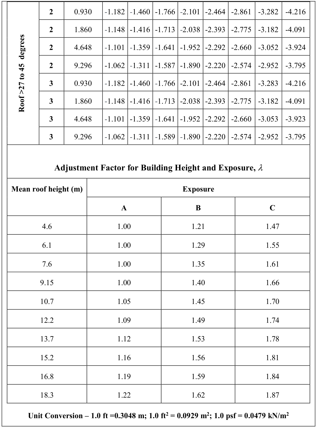
Net design wind pressures, , for the components and cladding of buildings designed using Method 1 represent the net pressures (sum of internal and external) to be applied normal to each building surface as shown in Figure 6.2.3. shall be determined by the following equation: Where, = adjustment factor for building height and exposure from Figure 6.2.3 = topographic factor as defined in Sec 2.4.7 evaluated at mean roof height, h = importance factor as defined in Sec 2.4.5 net design wind pressure for Exposure A, at m, and for , refer to Figure 6-3 of ASCE 7-05. Minimum Pressures: The positive design wind pressures, , from this Section shall not be less than +0.5 kN/m2 , and the negative design wind pressures, , from this Section shall not be less than −0.5 kN/m2 .2.4.2.4.3 Air permeable cladding
Design wind loads determined from Figure 6.2.3 shall be used for all air permeable cladding unless approved test data or the recognized literature demonstrate lower loads for the type of air permeable cladding being considered.2.4.3 Method 2: Analytical Procedure
2.4.3.1 Scopes and limitations
A building or other structure whose design wind loads are determined in accordance with this Section shall meet all of the following conditions:- (1) The building or other structure is a regular-shaped building or structure as defined in Sec 2.1.3.
- (2) The building or other structure does not have response characteristics making it subject to across-wind loading, vortex shedding, instability due to galloping or flutter; or does not have a site location for which channeling effects or buffeting in the wake of upwind obstructions warrant special consideration.
2.4.3.2 Shielding
There shall be no reductions in velocity pressure due to apparent shielding afforded by buildings and other structures or terrain features.2.4.3.3 Air permeable cladding
Design wind loads determined from Sec 2.4.3 shall be used for air permeable cladding unless approved test data or recognized literature demonstrate lower loads for the type of air permeable cladding being considered.2.4.3.4 Design procedure
- (1) The basic wind speed and wind directionality factor 0 shall be determined in accordance with Sec 2.4.4.
- (2) An importance factor . shall be determined in accordance with Sec 2.4.5.
- (3) An exposure category or exposure categories and velocity pressure exposure coefficient 0/ or 03, as applicable, shall be determined for each wind direction in accordance with Sec 2.4.6.
- (4) A topographic factor shall be determined in accordance with Sec 2.4.7.
- (5) A gust effect factor , or ,, as applicable, shall be determined in accordance with Sec 2.4.8.
- (6) An enclosure classification shall be determined in accordance with Sec 2.4.9.
- (7) Internal pressure coefficient ,! shall be determined in accordance with Sec 2.4.10.1.
- (8) External pressure coefficients ! or ,!, or force coefficients , as applicable, shall be determined in accordance with Sections 2.4.10.2 or 2.4.10.3, respectively.
- (9) Velocity pressure X/ or X3, as applicable, shall be determined in accordance with Sec 2.4.9.5.
- (10) Design wind load ; or & shall be determined in accordance with Sec 2.4.11.
2.4.4 Basic Wind Speed
The basic wind speed, used in the determination of design wind loads on buildings and other structures shall be as given in Figure 6.2.1 except as provided in Sec 2.4.4.1. The wind shall be assumed to come from any horizontal direction.2.4.4.1 Special wind regions
The basic wind speed shall be increased where records or experience indicate that the wind speeds are higher than those reflected in Figure 6.2.1. Mountainous terrain, gorges, and special regions shall be examined for unusual wind conditions. The authority having jurisdiction shall, if necessary, adjust the values given in Figure 6.2.1 to account for higher local wind speeds. Such adjustment shall be based on adequate meteorological information and other necessary data.2.4.4.2 Limitation
Tornadoes have not been considered in developing the basic wind-speed distributions.2.4.4.3 Wind directionality factor
The wind directionality factor, 0 shall be determined from Table 6.2.12. This factor shall only be applied when used in conjunction with load combinations specified in this Chapter.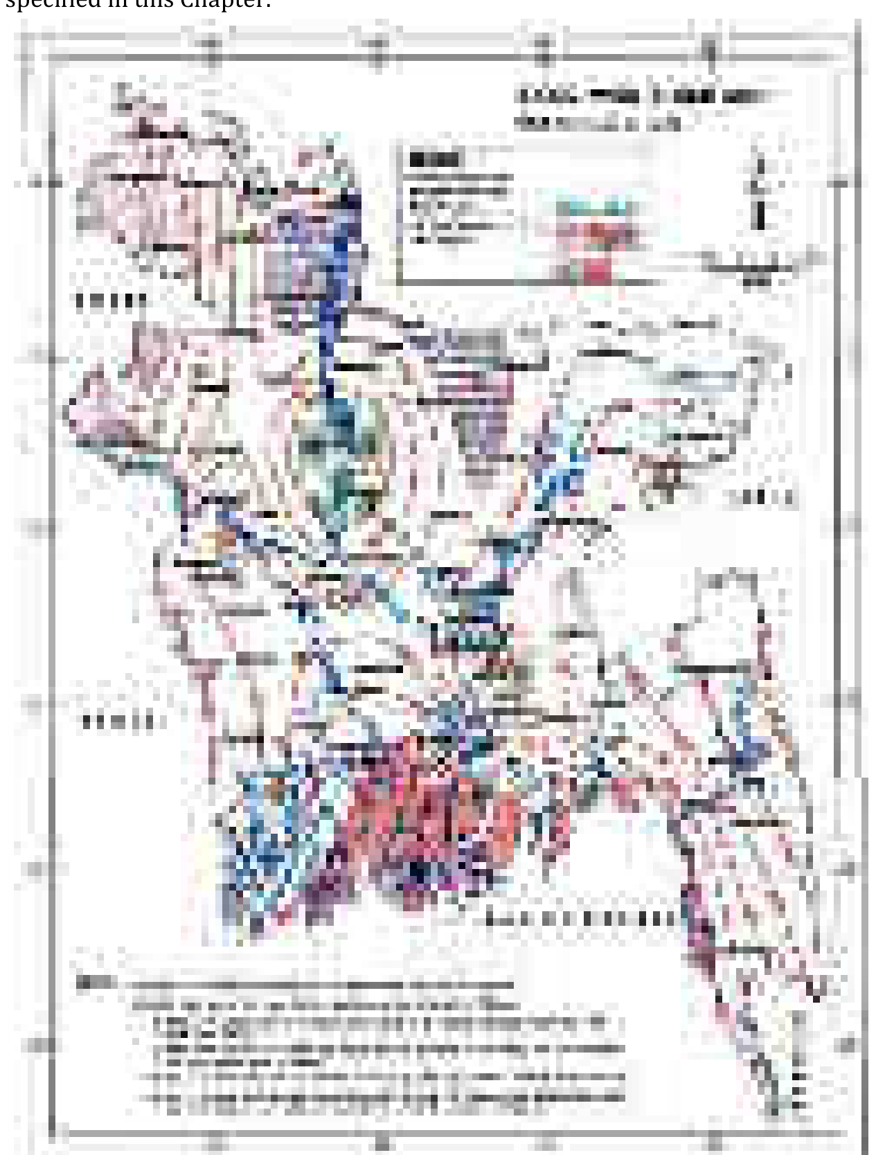
2.4.5 Importance Factor
An importance factor, . for the building or other structure shall be determined from Table 6.2.9 based on building and structure categories listed in Sec 1.2.4.2.4.6 Exposure
For each wind direction considered, the upwind exposure category shall be based on ground surface roughness that is determined from natural topography, vegetation, and constructed facilities.2.4.6.1 Wind directions and sectors
For each selected wind direction at which the wind loads are to be evaluated, the exposure of the building or structure shall be determined for the two upwind sectors extending 45o either side of the selected wind direction. The exposures in these two sectors shall be determined in accordance with Sections 2.4.6.2 and 2.4.6.3 and the exposure resulting in the highest wind loads shall be used to represent the winds from that direction.2.4.6.2 Surface roughness categories
A ground surface roughness within each 45o sector shall be determined for a distance upwind of the site as defined in Sec 2.4.6.3 from the categories defined in the following text, for the purpose of assigning an exposure category as defined in Sec 2.4.6.3. Surface Roughness A: Urban and suburban areas, wooded areas, or other terrain with numerous closely spaced obstructions having the size of single-family dwellings or larger. Surface Roughness B: Open terrain with scattered obstructions having heights generally less than 9.1 m. This category includes flat open country, grasslands, and all water surfaces in cyclone prone regions. Surface Roughness C: Flat, unobstructed areas and water surfaces outside cyclone prone regions. This category includes smooth mud flats and salt flats.2.4.6.3 Exposure categories
Exposure A: Exposure A shall apply where the ground surface roughness condition, as defined by Surface Roughness A, prevails in the upwind direction for a distance of at least 792 m or 20 times the height of the building, whichever is greater. Exception: For buildings whose mean roof height is less than or equal to 9.1 m, the upwind distance may be reduced to 457 m. Exposure B: Exposure B shall apply for all cases where Exposures A or C do not apply. Exposure C: Exposure C shall apply where the ground surface roughness, as defined by Surface Roughness C, prevails in the upwind direction for a distance greater than 1,524 m or 20 times the building height, whichever is greater. Exposure C shall extend into downwind areas of Surface Roughness A or B for a distance of 200 m or 20 times the height of the building, whichever is greater. For a site located in the transition zone between exposure categories, the category resulting in the largest wind forces shall be used. Exception: An intermediate exposure between the preceding categories is permitted in a transition zone provided that it is determined by a rational analysis method defined in the recognized literature.2.4.6.4 Exposure category for main wind-force resisting system
Buildings and Other Structures: For each wind direction considered, wind loads for the design of the MWFRS determined from Figure 6.2.6 shall be based on the exposure categories defined in Sec 2.4.6.3. Low-Rise Buildings: Wind loads for the design of the MWFRSs for low-rise buildings shall be determined using a velocity pressure X3 based on the exposure resulting in the highest wind loads for any wind direction at the site where external pressure coefficients ,! given in Figure 6.2.10 are used.2.4.6.5 Exposure category for components and cladding
Components and cladding design pressures for all buildings and other structures shall be based on the exposure resulting in the highest wind loads for any direction at the site.2.4.6.6 Velocity pressure exposure coefficient
Based on the exposure category determined in Sec 2.4.6.3, a velocity pressure exposure coefficient or , as applicable, shall be determined from Table 6.2.11. For a site located in a transition zone between exposure categories that is near to a change in ground surface roughness, intermediate values of or between those shown in Table 6.2.11, are permitted, provided that they are determined by a rational analysis method defined in the recognized literature.2.4.7 Topographic Effects
2.4.7.1 Wind speed-up over hills, ridges and escarpments
Wind speed-up effects at isolated hills, ridges, and escarpments constituting abrupt changes in the general topography located in any exposure category shall be included in the design when buildings and other site conditions and locations of structures meet all of the following conditions:- (i) The hill, ridge, or escarpment is isolated and unobstructed upwind by other similar topographic features of comparable height for 100 times the height of the topographic feature (100 H) or 3.22 km, whichever is less. This distance shall be measured horizontally from the point at which the height H of the hill, ridge, or escarpment is determined.
- (ii) The hill, ridge, or escarpment protrudes above the height of upwind terrain features within a 3.22 km radius in any quadrant by a factor of two or more.
- (iii)The structure is located as shown in Figure 6.2.4 in the upper one-half of a hill or ridge or near the crest of an escarpment.
- (iv)
- (v) is greater than or equal to 4.5 m for Exposures B and C and 18.3 m for Exposure A.
2.4.7.2 Topographic factor
The wind speed-up effect shall be included in the calculation of design wind loads by using the factor : Where, , , and are given in Figure 6.2.4. If site conditions and locations of structures do not meet all the conditions specified in Sec 2.4.7.1 then = 1.0.2.4.8 Gust Effect Factor
2.4.8.1 Rigid structures
For rigid structures as defined in Sec 2.1.3, the gust-effect factor shall be taken as 0.85 or calculated by the formula: Where, the intensity of turbulence at height where the equivalent height of the structure defined as 0.6h, but not less than for all building heights . and c are listed for each exposure in Table 6.2.10; and the value of shall be taken as 3.4. The background response Q is given by Where, B, h are defined in Sec 2.1.4; and the integral length scale of turbulence at the equivalent height given by In which l and are constants listed in Table 6.2.10.2.4.8.2 Flexible or dynamically sensitive structures
For flexible or dynamically sensitive structures as defined in Sec 2.1.3 (natural period greater than 1.0 second), the gust-effect factor shall be calculated by The value of both and shall be taken as 3.4 and is given by , the resonant response factor, is given by Where, the subscript in Eq. 6.2.15 shall be taken as , and , respectively, where , and are defined in Sec 2.1.4. building natural frequency setting setting setting damping ratio, percent of critical mean hourly wind speed at height determined from Eq. 6.2.16.2.4.8.3 Rational analysis
In lieu of the procedure defined in Sections 2.4.8.1 and 2.4.8.2, determination of the gust-effect factor by any rational analysis defined in the recognized literature is permitted.2.4.8.4 Limitations
Where combined gust-effect factors and pressure coefficients are given in figures and tables, the gust-effect factor shall not be determined separately.2.4.9 Enclosure Classifications
2.4.9.1 General
For the purpose of determining internal pressure coefficients, all buildings shall be classified as enclosed, partially enclosed, or open as defined in Sec 2.1.3.2.4.9.2 Openings
A determination shall be made of the amount of openings in the building envelope to determine the enclosure classification as defined in Sec 2.4.9.3.2.4.9.3 Wind-borne debris
Glazing in buildings located in wind-borne debris regions shall be protected with an impact-resistant covering or be impact-resistant glazing according to the requirements specified in ASTM E1886 and ASTM E1996 or other approved test methods and performance criteria. The levels of impact resistance shall be a function of Missile Levels and Wind Zones specified in ASTM E1886 and ASTM E1996. Exceptions:- (i) Glazing in Category II, III, or IV buildings located over 18.3 m above the ground and over 9.2 m above aggregate surface roofs located within 458 m of the building shall be permitted to be unprotected.
- (ii) Glazing in Category I buildings shall be permitted to be unprotected.
2.4.9.4 Multiple classifications
If a building by definition complies with both the “open” and “partially enclosed” definitions, it shall be classified as an “open” building. A building that does not comply with either the “open” or “partially enclosed” definitions shall be classified as an “enclosed” building.2.4.9.5 Velocity pressure
Velocity pressure, evaluated at height shall be calculated by the following equation: Where is the wind directionality factor, is the velocity pressure exposure coefficient defined in Sec 2.4.6.6, is the topographic factor defined in Sec 2.4.7.2, and is the velocity pressure calculated using Eq. 6.2.17 at mean roof height . The numerical coefficient 0.000613 shall be used except where sufficient climatic data are available to justify the selection of a different value of this factor for a design application.2.4.10 Pressure And Force Coefficients
2.4.10.1 Internal pressure coefficients
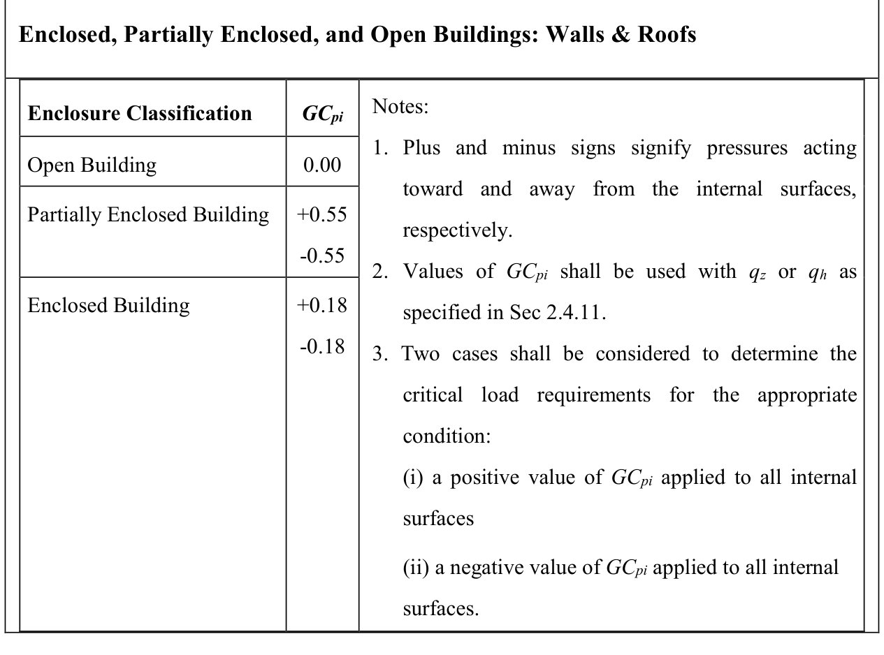
Internal Pressure Coefficient. Internal pressure coefficients, shall be determined from Figure 6.2.5 based on building enclosure classifications determined from Sec 2.4.9. Reduction Factor for Large Volume Buildings, : For a partially enclosed building containing a single, unpartitioned large volume, the internal pressure coefficient, shall be multiplied by the following reduction factor, : Where, = total area of openings in the building envelope (walls and roof, in m2) = unpartitioned internal volume, in m3 Where, 5 total area of openings in the building envelope (walls and roof, in m2 )2.4.10.2 External pressure coefficients
Main Wind-Force Resisting Systems: External pressure coefficients for MWFRSs are given in Figures 6.2.6 to 6.2.8. Combined gust effect factor and external pressure coefficients, are given in Figure 6.2.10 for low-rise buildings. The pressure coefficient values and gust effect factor in Figure 6.2.10 shall not be separated. Components and Cladding : Combined gust effect factor and external pressure coefficients for components and cladding are given in Figures 6.2.11 to 6.2.17. The pressure coefficient values and gust-effect factor shall not be separated.2.4.10.3 Force coefficients
Force coefficients are given in Figures 6.2.20 to 6.2.23.2.4.10.4 Roof overhangs
Main Wind-Force Resisting System: Roof overhangs shall be designed for a positive pressure on the bottom surface of windward roof overhangs corresponding to in combination with the pressures determined from using Figures 6.2.6 and 6.2.10. Components and Cladding: For all buildings, roof overhangs shall be designed for pressures determined from pressure coefficients given in Figure 6.2.11.2.4.10.5 Parapets
Main Wind-Force Resisting System: The pressure coefficients for the effect of parapets on the MWFRS loads are given in Sec 2.4.12.2. Components and Cladding: The pressure coefficients for the design of parapet component and cladding elements are taken from the wall and roof pressure coefficients as specified in Sec 2.4.12.3.2.4.11 Design Wind Loads on Enclosed and Partially Enclosed Buildings
2.4.11.1 General
Sign Convention: Positive pressure acts toward the surface and negative pressure acts away from the surface. Critical Load Condition: Values of external and internal pressures shall be combined algebraically to determine the most critical load. Tributary Areas Greater than 65 m2 : Component and cladding elements with tributary areas greater than 65 m2 shall be permitted to be designed using the provisions for MWFRSs.2.4.11.2 Main wind-force resisting systems
Rigid Buildings of All Heights: Design wind pressures for the MWFRS of buildings of all heights shall be determined by the following equation: Where, for windward walls evaluated at height above the ground for leeward walls, side walls, and roofs, evaluated at height- for windward walls, side walls, leeward walls, and roofs of enclosed buildings and for negative internal pressure evaluation in partially enclosed buildings.
- external pressure coefficient from Figures 6.2.6 or 6.2.8
- Combined net pressure on the parapet due to the combination of the net pressures from the front and back parapet surfaces. Plus (and minus) signs signify net pressure acting toward (and away from) the front (exterior) side of the parapet
- Velocity pressure evaluated at the top of the parapet
2.4.11.3 Design wind load cases
The MWFRS of buildings of all heights, whose wind loads have been determined under the provisions of Sec 2.4.11.2, shall be designed for the wind load cases as defined in Figure 6.2.9. The eccentricity for rigid structures shall be measured from the geometric center of the building face and shall be considered for each principal axis . The eccentricity for flexible structures shall be determined from the following equation and shall be considered for each principal axis : Where, Eccentricity e as determined for rigid structures in Figure 6.2.9 Distance between the elastic shear center and center of mass of each floor shall be as defined in Sec 2.1.4 The sign of the eccentricity shall be plus or minus, whichever causes the more severe load effect. Exception: One-story buildings with h less than or equal to 9.1 m, buildings two stories or less framed with light-frame construction, and buildings two stories or less designed with flexible diaphragms need only be designed for Load Case 1 and Load Case 3 in Figure 6.2.9.2.4.11.4 Components and cladding.
Low-Rise Buildings and Buildings with ℎ≤18.3 m: Design wind pressures on component and cladding elements of low-rise buildings and buildings with ℎ≤ 18.3 m shall be determined from the following equation: Where, Velocity pressure evaluated at mean roof height ℎ using exposure defined in Sec 2.4.6.5 External pressure coefficients given in Figures 6.2.11 to 6.2.16 Internal pressure coefficient given in Figure 6.2.5 Buildings with ℎ> 18.3 m: Design wind pressures on components and cladding for all buildings with ℎ> 18.3 m shall be determined from the following equation: Where, for windward walls calculated at height 4 above the ground for leeward walls, side walls, and roofs, evaluated at height ℎ for windward walls, side walls, leeward walls, and roofs of enclosed buildings and for negative internal pressure evaluation in partially enclosed buildings for positive internal pressure evaluation in partially enclosed buildings where height 4 is defined as the level of the highest opening in the building that could affect the positive internal pressure. For buildings sited in wind-borne debris regions, glazing that is not impact resistant or protected with an impact-resistant covering, shall be treated as an opening in accordance with Sec 2.4.9.3. For positive internal pressure evaluation, qi may conservatively be evaluated at height ℎ () external pressure coefficient from Figure 6.2.17. internal pressure coefficient given in Figure 6.2.5. and shall be evaluated using exposure defined in Sec 2.4.6.3.2.4.11.5 Alternative design wind pressures for components and cladding in buildings with 18.3 m < ℎ< 27.4 m.
Alternative to the requirements of Sec 2.4.11.2, the design of components and cladding for buildings with a mean roof height greater than 18.3 m and less than 27.4 m values from Figures 6.2.11 to 6.2.17 shall be used only if the height to width ratio is one or less (except as permitted by Notes of Figure 6.2.17) and Eq. 6.2.24 is used. Parapets: The design wind pressure on the components and cladding elements of parapets shall be designed by the following equation: Where, X! 5 Velocity pressure evaluated at the top of the parapet ,! 5 External pressure coefficient from Figures 6.2.11 to 6.2.17 ,! 5 Internal pressure coefficient from Figure 6.2.5, based on the porosity of the parapet envelope. Two load cases shall be considered. Load Case A shall consist of applying the applicable positive wall pressure from Figures 6.2.11 or 6.2.17 to the front surface of the parapet while applying the applicable negative edge or corner zone roof pressure from Figures 6.2.11 to 6.2.17 to the back surface. Load Case B shall consist of applying the applicable positive wall pressure from Figures 6.2.11 or 6.2.17 to the back of the parapet surface, and applying the applicable negative wall pressure from Figures 6.2.11 or 6.2.17 to the front surface. Edge and corner zones shall be arranged as shown in Figures 6.2.11 to 6.2.17. ,! shall be determined for appropriate roof angle and effective wind area from Figures 6.2.11 to 6.2.17. If internal pressure is present, both load cases should be evaluated under positive and negative internal pressure.2.4.12 Design Wind Loads on Open Buildings with Monoslope, Pitched, or Troughed Roofs
2.4.12.1 General
Sign Convention: Plus and minus signs signify pressure acting toward and away from the top surface of the roof, respectively. Critical Load Condition: Net pressure coefficients CN include contributions from top and bottom surfaces. All load cases shown for each roof angle shall be investigated.2.4.12.2 Main wind-force resisting systems
The net design pressure for the MWFRSs of monoslope, pitched, or troughed roofs shall be determined by the following equation: Where,- X3 5 Velocity pressure evaluated at mean roof height h using the exposure as defined in Sec 2.4.6.3 that results in the highest wind loads for any wind direction at the site
- , 5 Gust effect factor from Sec 2.4.8
- 5 Net pressure coefficient determined from Figures 6.2.18(a) to 6.2.18(d).
2.4.12.3 Component and cladding elements
The net design wind pressure for component and cladding elements of monoslope, pitched, and troughed roofs shall be determined by the following equation: Where,- X3 5 Velocity pressure evaluated at mean roof height ℎ using the exposure as defined in Sec 2.4.6.3 that results in the highest wind loads for any wind direction at the site
- , 5 Gust-effect factor from Sec 2.4.8
- 5 Net pressure coefficient determined from Figures 6.2.19(a) to 6.2.19(c).
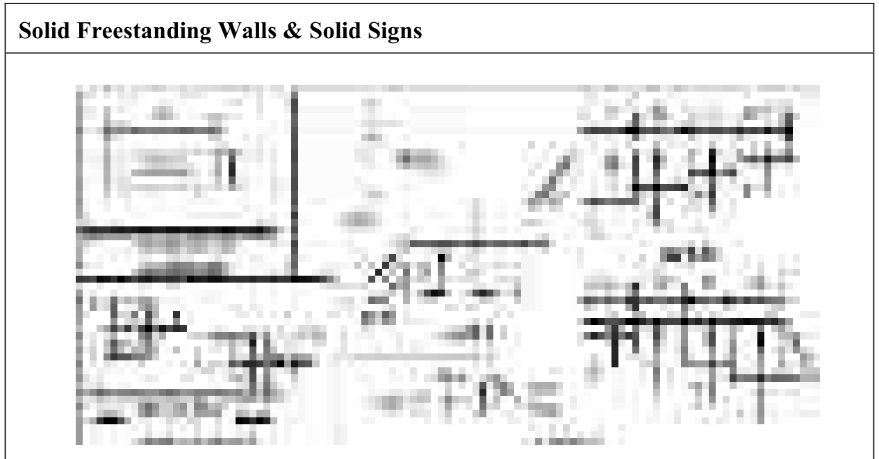
2.4.13 Design Wind Loads on Solid Free Standing Walls and Solid Signs
The design wind force for solid freestanding walls and solid signs shall be determined by the following formula: Where,- X3 5 Velocity pressure evaluated at height ℎ (Figure 6.2.20) using exposure defined in Sec2.4.6.3
- , 5 Gust-effect factor from Sec 2.4.8
- 5 Net force coefficient from Figure 6.2.20
- 5 Gross area of the solid freestanding wall or solid sign, in m2
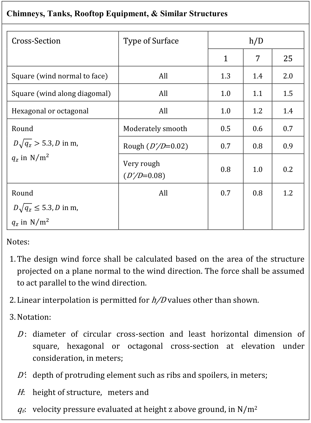
2.4.14 Design Wind Loads on Other Structures
The design wind force for other structures shall be determined by the following equation: Where,- = Velocity pressure evaluated at height of the centroid of area using exposure as in Sec 2.4.6.3
- = Gust-effect factor from Sec 2.4.8
- = Force coefficients from Figures 6.2.21 to 6.2.23.
- = Projected area normal to the wind except where is specified for the actual surface area, m2
2.4.15 Rooftop Structures and Equipment for Buildings with h ≤ 18.3 m
The force on rooftop structures and equipment with less than located on buildings with m shall be determined from Eq. 6.2.30, increased by a factor of 1.9. The factor shall be permitted to be reduced linearly from 1.9 to 1.0 as the value of is increased from to .2.4.16 Method 3 - Wind Tunnel Procedure
2.4.16.1 Scope
Wind tunnel tests shall be used where required by Sec 2.4.3.1. Wind tunnel testing shall be permitted in lieu of Methods 1 and 2 for any building or structure.2.4.16.2 Test conditions
Wind tunnel tests, or similar tests employing fluids other than air, used for the determination of design wind loads for any building or other structure, shall be conducted in accordance with this Section. Tests for the determination of mean and fluctuating forces and pressures shall meet all of the following conditions:- (i) Natural atmospheric boundary layer has been modeled to account for the variation of wind speed with height.
- (ii) The relevant macro- (integral) length and micro-length scales of the longitudinal component of atmospheric turbulence are modeled to approximately the same scale as that used to model the building or structure.
- (iii) The modeled building or other structure and surrounding structures and topography are geometrically similar to their full-scale counterparts, except that, for low-rise buildings meeting the requirements of Sec 2.4.3.1, tests shall be permitted for the modeled building in a single exposure site as in Sec 2.4.6.
- (iv) The projected area of the modeled building or other structure and surroundings is less than 8 percent of the test section cross-sectional area unless correction is made for blockage.
- (v) The longitudinal pressure gradient in the wind tunnel test section is accounted for.
- (vi) Reynolds number effects on pressures and forces are minimized.
- (vii) Response characteristics of the wind tunnel instrumentation are consistent with the required measurements.
2.4.17 Dynamic Response
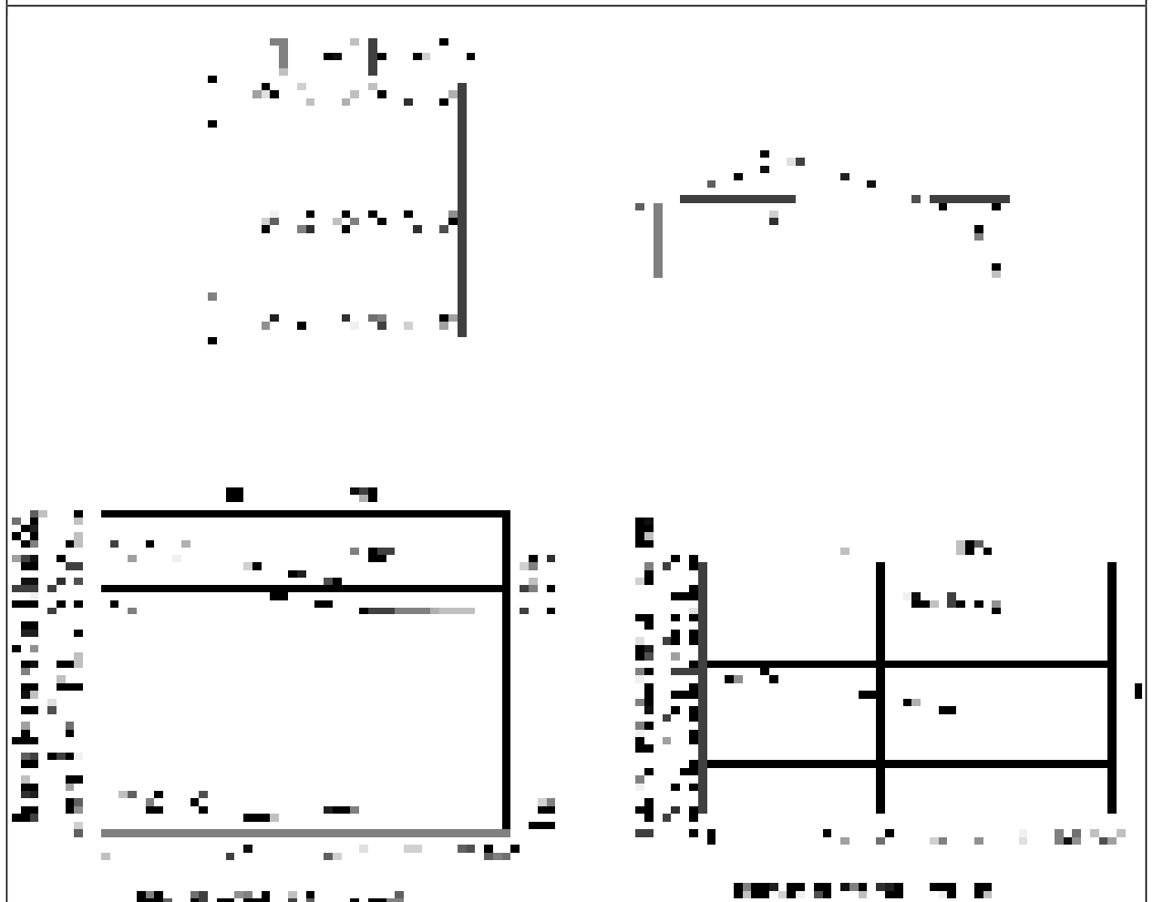
Tests for the purpose of determining the dynamic response of a building or other structure shall be in accordance with Sec 2.4.16.2. The structural model and associated analysis shall account for mass distribution, stiffness, and damping. Enclosed Buildings: Walls & Roofs Notes:- Pressures shown are applied to the horizontal and vertical projections, for exposure A, at h =9.1m , I =1.0, and Kzt = 1.0. Adjust to other conditions using Equation 6.2.3.
- The load patterns shown shall be applied to each corner of the building in turn as the reference corner. (See Figure 6.2.10)
- For the design of the longitudinal MWFRS use θ = 0°, and locate the zone E/F, G/H boundary at the mid-length of the building.
- Load cases 1 and 2 must be checked for 25° < θ ≤ 45°. Load case 2 at 25° is provided only for interpolation between 25° to 30°.
- Plus and minus signs signify pressures acting toward and away from the projected surfaces, respectively.
- For roof slopes other than those shown, linear interpolation is permitted.
- The total horizontal load shall not be less than that determined by assuming ps = 0 in zones B & D.
- The zone pressures represent the following:
- Horizontal pressure zones – Sum of the windward and leeward net (sum of internal and external) pressures on vertical projection of:
- A - End zone of wall C - Interior zone of wall
- B - End zone of roof D - Interior zone of roof
- Vertical pressure zones – Net (sum of internal and external) pressures on horizontal projection of:
- E - End zone of windward roof G - Interior zone of windward roof
- Where zone E or G falls on a roof overhang on the windward side of the building, use EOH and GOH for the pressure on the horizontal projection of the overhang. Overhangs on the leeward and side edges shall have the basic zone pressure applied.
- Notation:
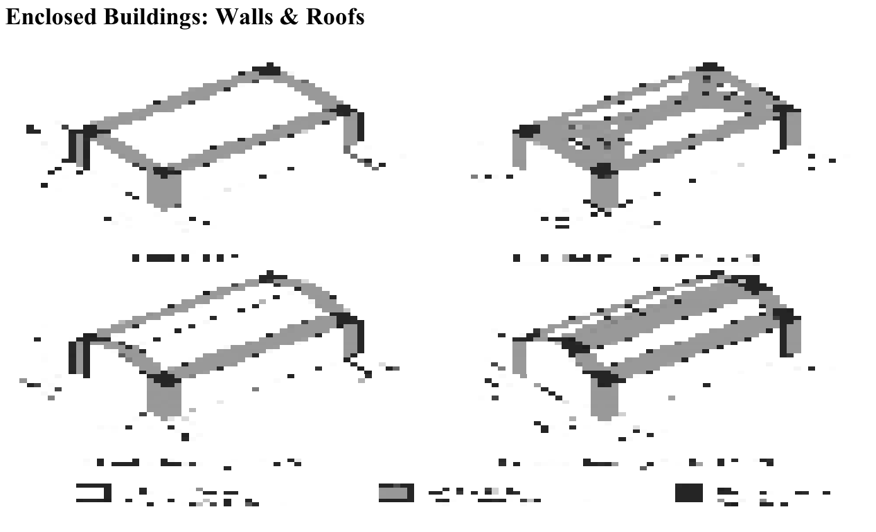
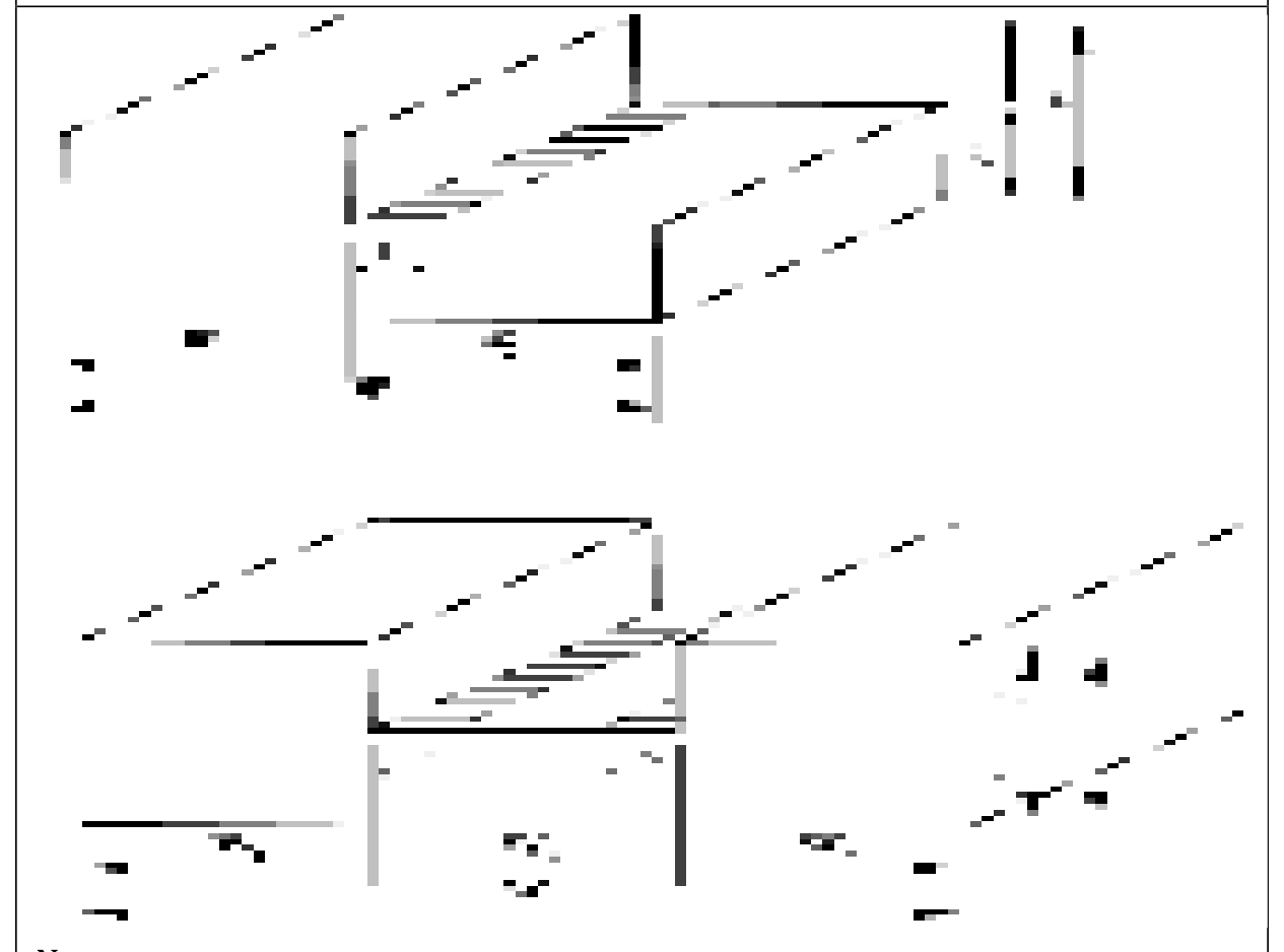
- Pressures shown are applied normal to the surface, for exposure A, at h = 9.1m, I = 1.0, and Kzt = 1.0. Adjust to other conditions using Equation 6.2.4.
- Plus and minus signs signify pressures acting toward and away from the surfaces, respectively. 3. For hip roofs with θ ≤ 25°, Zone 3 shall be treated as Zone 2.
- For effective wind areas between those given, value may be interpolated, otherwise use the value associated with the lower effective wind area. 5. Notation:
- a : 10 percent of least horizontal dimension or 0.4h, whichever is smaller, but not less than either 4% of least horizontal dimension or 0.9 m.
- h : Mean roof height, in feet (meters), except that eave height shall be used for roof angles <10°. θ : Angle of plane of roof from horizontal, in degrees.
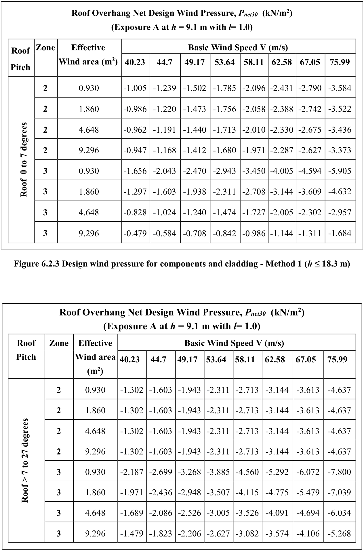
Unit Conversion – 1.0 ft =0.3048 m; 1.0 ft2** = 0.0929 m**2; 1.0 psf = 0.0479 kN/m2
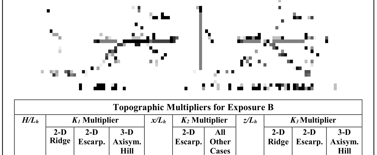
- For values of H/Lh , x/Lh and z/Lh other than those shown, linear interpolation is permitted. 2. For H/Lh > 0.5, assume H/Lh = 0.5 for evaluating K 1 and substitute 2H for Lh for evaluating K 2 and K 3.
- Multipliers are based on the assumption that wind approaches the hill or escarpment along the direction of maximum slope.
- Notation:
- K1 : Factor to account for shape of topographic feature and maximum speed-up effect.
- K2 : Factor to account for reduction in speed-up with distance upwind or downwind of crest.
- K3 : Factor to account for reduction in speed-up with height above local terrain. x : Distance (upwind or downwind) from the crest to the building site, in meters.
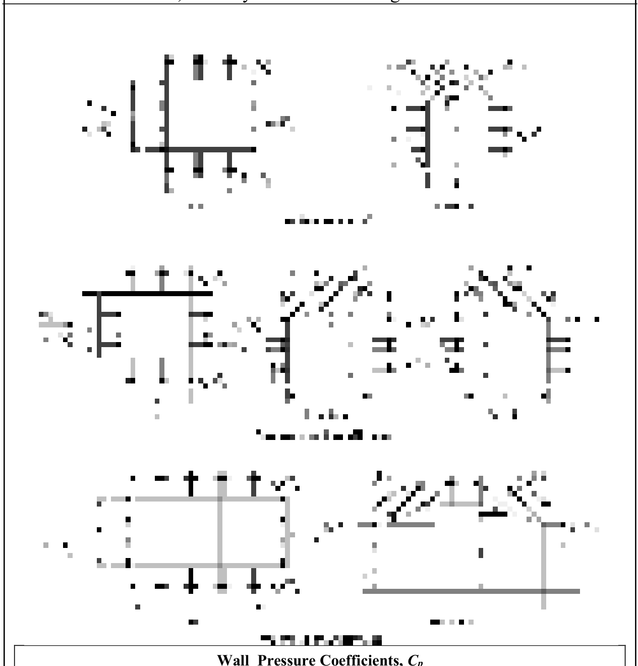
- Plus and minus signs signify pressures acting toward and away from the surfaces, respectively.
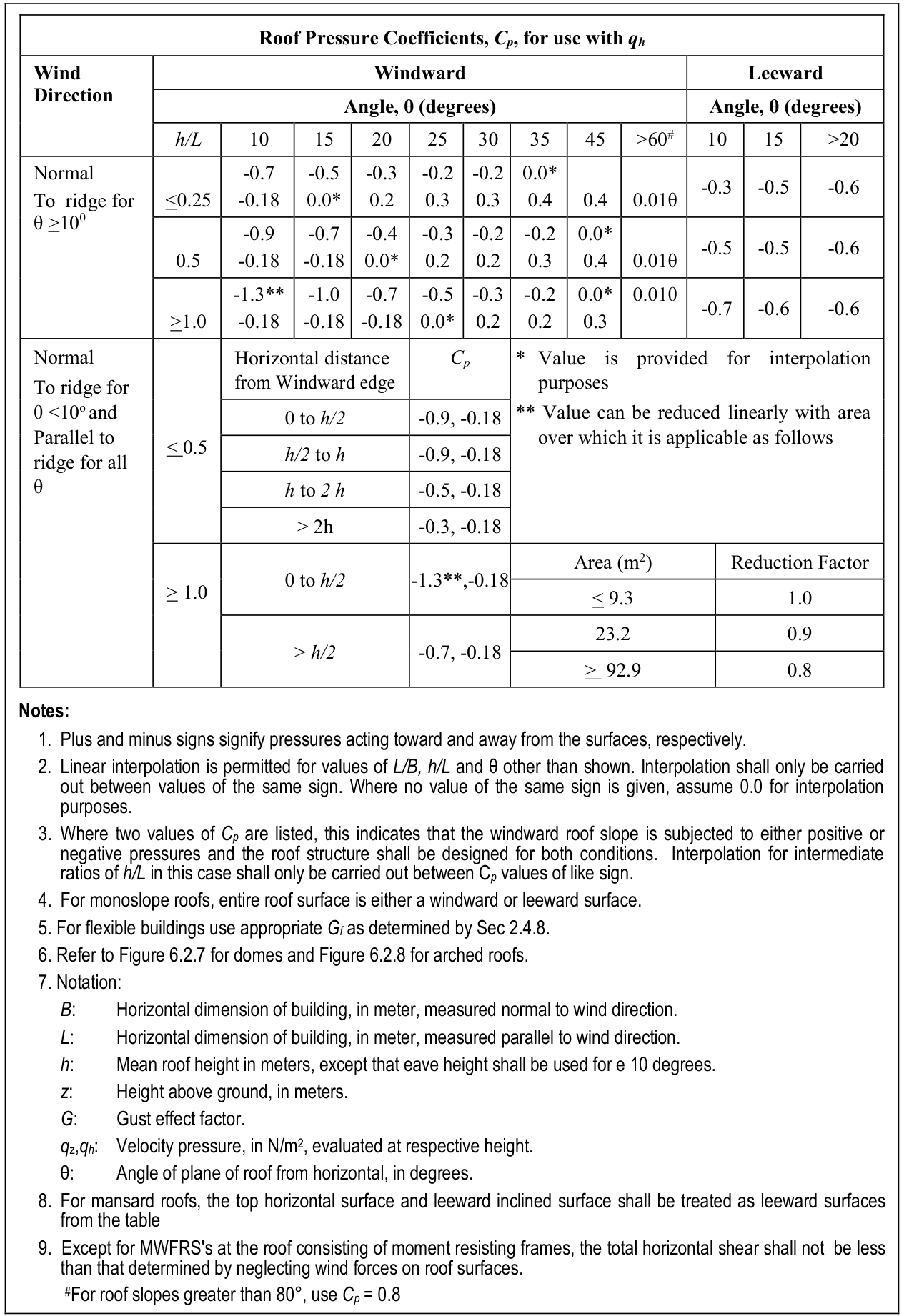
- Linear interpolation is permitted for values of L/B, h/L and θ other than shown. Interpolation shall only be carried out between values of the same sign. Where no value of the same sign is given, assume 0.0 for interpolation purposes.
- Where two values of Cp are listed, this indicates that the windward roof slope is subjected to either positive or negative pressures and the roof structure shall be designed for both conditions. Interpolation for intermediate ratios of h/L in this case shall only be carried out between C p values of like sign. 4. For monoslope roofs, entire roof surface is either a windward or leeward surface. 5. For flexible buildings use appropriate Gf as determined by Sec 2.4.8. 6. Refer to Figure 6.2.7 for domes and Figure 6.2.8 for arched roofs. 7. Notation: B : Horizontal dimension of building, in meter, measured normal to wind direction. L : Horizontal dimension of building, in meter, measured parallel to wind direction. h : Mean roof height in meters, except that eave height shall be used for e 10 degrees. z : Height above ground, in meters. G : Gust effect factor. q z, qh : Velocity pressure, in N/m2 , evaluated at respective height. θ: Angle of plane of roof from horizontal, in degrees. 8. For mansard roofs, the top horizontal surface and leeward inclined surface shall be treated as leeward surfaces from the table 9. Except for MWFRS’s at the roof consisting of moment resisting frames, the total horizontal shear shall not be less than that determined by neglecting wind forces on roof surfaces. #For roof slopes greater than 80°, use Cp = 0.8
- Two load cases shall be considered:
- Case A. Cp values between A and B and between B and C shall be determined by linear interpolation along arcs on the dome parallel to the wind direction;
- Case B. Cp shall be the constant value of A for θ ≤ 25 degrees, and shall be determined by linear interpolation from 25 degrees to B and from B to C.
- Values denote Cp to be used with where (hD + f) is the height at the top of the dome.
- Plus and minus signs signify pressures acting toward and away from the surfaces, respectively.
- Cp is constant on the dome surface for arcs of circles perpendicular to the wind direction; for example, the arc passing through B-B-B and all arcs parallel to B-B-B.
- For values of hD/D between those listed on the graph curves, linear interpolation shall be permitted.
- θ50 degrees on dome springline, θ590 degrees at dome center top point. f is measured from springline to top.
- The total horizontal shear shall not be less than that determined by neglecting wind forces roof surfaces.
- For f/D values less than 0.05, use Figure 6.2.6.
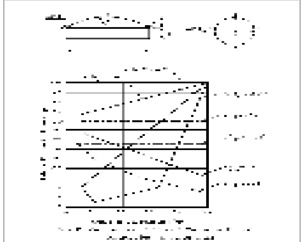
- When the rise-to-span ratio is 0.2 ≤ r ≤ 0.3, alternate coefficients given by (6 r - 2.1) shall also be used for the windward quarter.
- Values listed are for the determination of average load on main wind force resisting systems.
- Plus and minus signs signify pressures acting toward and away from the surfaces, respectively.
- For wind directed parallel to the axis of the arch, use pressure coefficients from Figure 6.2.6 with wind directed parallel to ridge.
- For components and cladding: (1) At roof perimeter, use the external pressure coefficients in Figure 6.2.11 with e based on spring-line slope and (2) for remaining roof areas, use external pressure coefficients of this Table multiplied by 0.87.
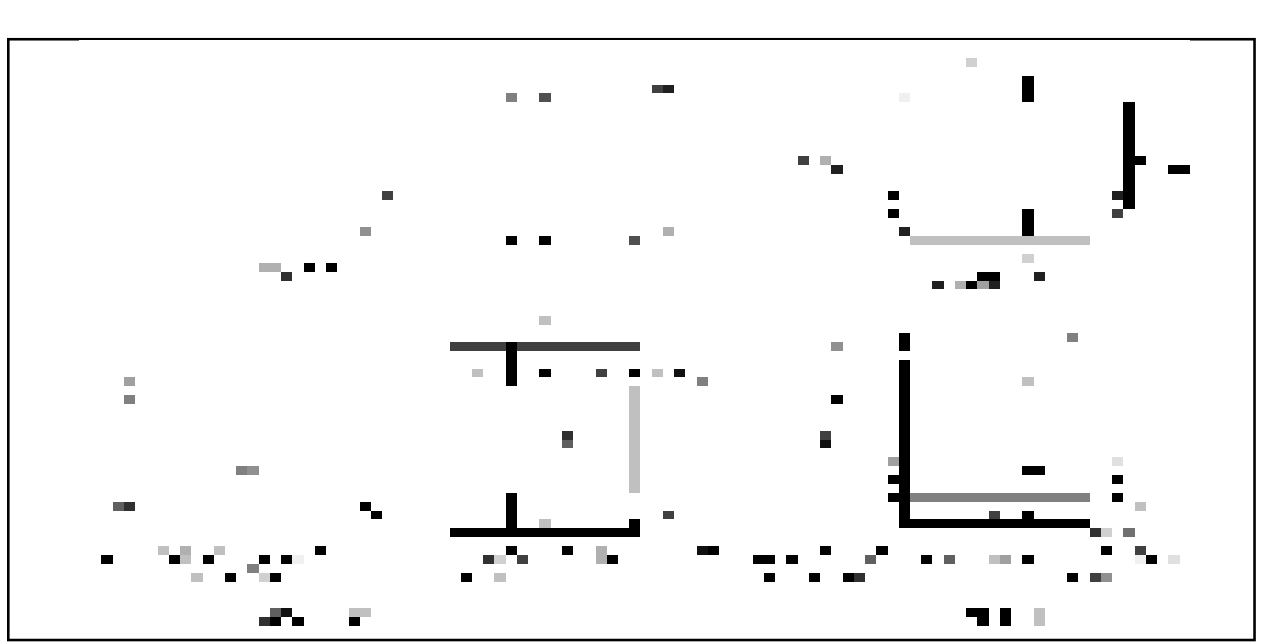
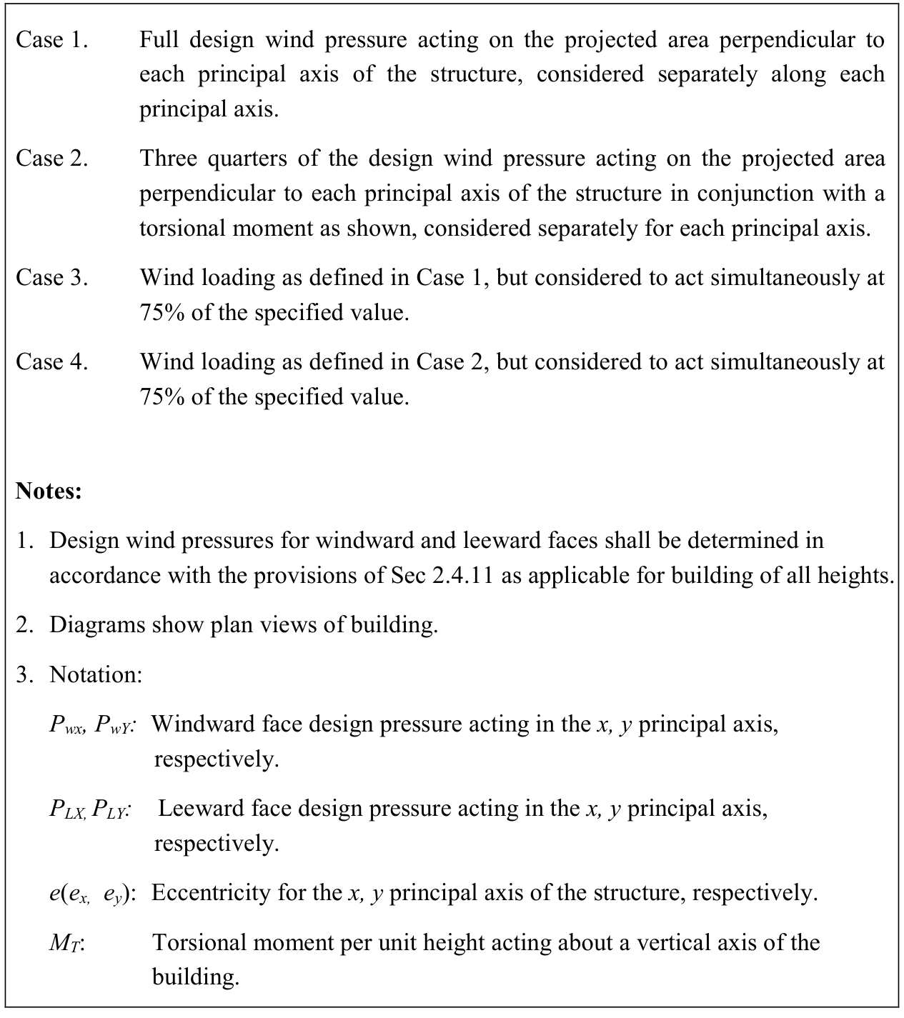
- Case 1. Full design wind pressure acting on the projected area perpendicular to each principal axis of the structure, considered separately along each principal axis.
- Case 2. Three quarters of the design wind pressure acting on the projected area perpendicular to each principal axis of the structure in conjunction with a torsional moment as shown, considered separately for each principal axis.
- Case 3. Wind loading as defined in Case 1, but considered to act simultaneously at 75% of the specified value.
- Case 4. Wind loading as defined in Case 2, but considered to act simultaneously at 75% of the specified value.
- Design wind pressures for windward and leeward faces shall be determined in accordance with the provisions of Sec 2.4.11 as applicable for building of all heights.
- Diagrams show plan views of building. 3. Notation: Pwx, PwY: Windward face design pressure acting in the x, y principal axis, respectively.
- Plus and minus signs signify pressures acting toward and away from the surfaces, respectively.
- For values of θ other than those shown, linear interpolation is permitted.
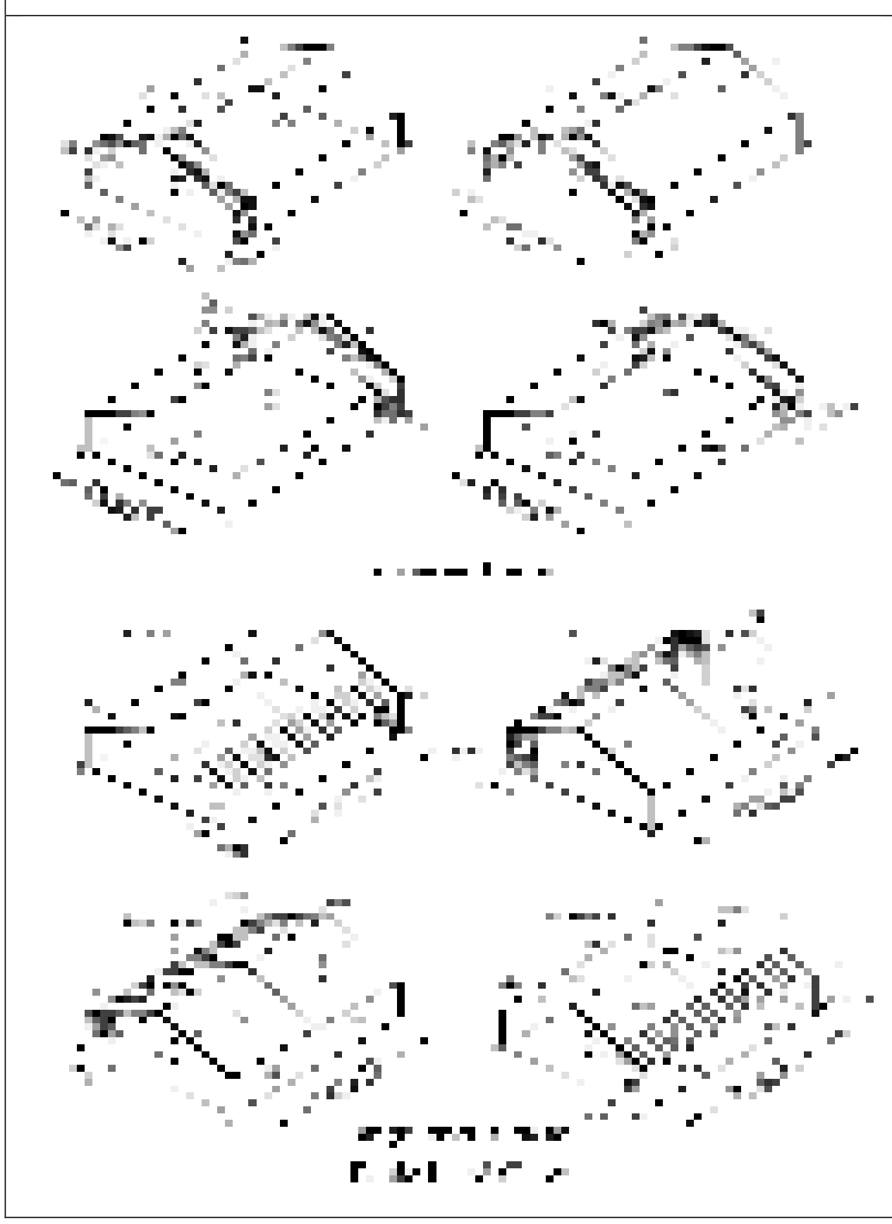
- The building must be designed for all wind directions using the 8 loading patterns shown. The load patterns are applied to each building corner in turn as the Reference Corner.
- Combinations of external and internal pressures (see Figure 6.2.5) shall be evaluated as required to obtain the most severe loadings.
- For the torsional load cases shown below, the pressures in zones designated with a “T” (1T, 2T, 3T, 4T) shall be 25% of the full design wind pressures (zones 1, 2, 3, 4). Exception: One story buildings with h less than or equal to 9.1m, buildings two stories or less framed with light frame construction, and buildings two stories or less designed with flexible diaphragms need not be designed for the torsional load cases.
- Torsional loading shall apply to all eight basic load patterns using the figures below applied at each reference corner.
- Except for moment-resisting frames, the total horizontal shear shall not be less than that determined by neglecting wind forces on roof surfaces.
- For the design of the MWFRS providing lateral resistance in a direction parallel to a ridge line or for flat roofs, use θ 5 0° and locate the zone 2/3 boundary at the mid-length of the building.
- The roof pressure coefficient GCpf, when negative in Zone 2 or 2E, shall be applied in Zone 2/2E for a distance from the edge of roof equal to 0.5 times the horizontal dimension of the building parallel to the direction of the MWFRS being designed or 2.5 times the eave height, he, at the windward wall, whichever is less; the remainder of Zone 2/2E extending to the ridge line shall use the pressure coefficient GCpf for Zone 3/3E.
- Notation:
- a: 10 percent of least horizontal dimension or 0.4h, whichever is smaller, but not less than either 4% of least horizontal dimension or 0.9 m. h: Mean roof height, in meters, except that eave height shall be used for θ ≤ 10°. θ: Angle of plane of roof from horizontal, in degrees.
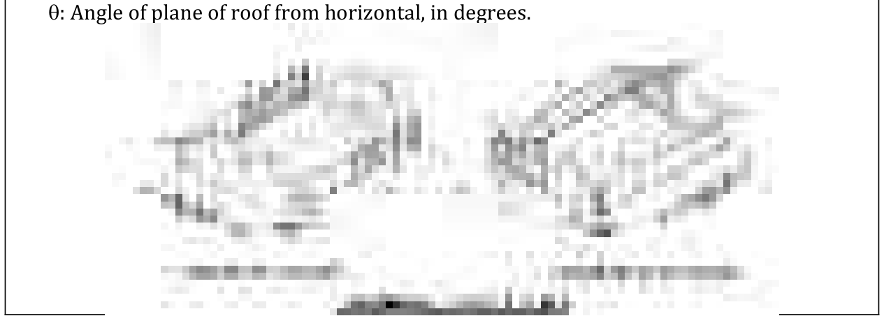
- Vertical scale denotes GCP to be used with qh.
- Horizontal scale denotes effective wind area, in square meters.
- Plus and minus signs signify pressures acting toward and away from the surfaces, respectively.
- Each component shall be designed for maximum positive and negative pressures.
- Values of GCP for walls shall be reduced by 10% when θ ≤ 100 .
- Notation:
- a: 10 percent of least horizontal dimension or 0.4h , whichever is smaller, but not less than either 4% of least horizontal dimension or 0.9m.
- h: Mean roof height, in meters, except that eave height shall be used for θ ≤ 100 . θ: Angle of plane of roof from horizontal, in degrees.
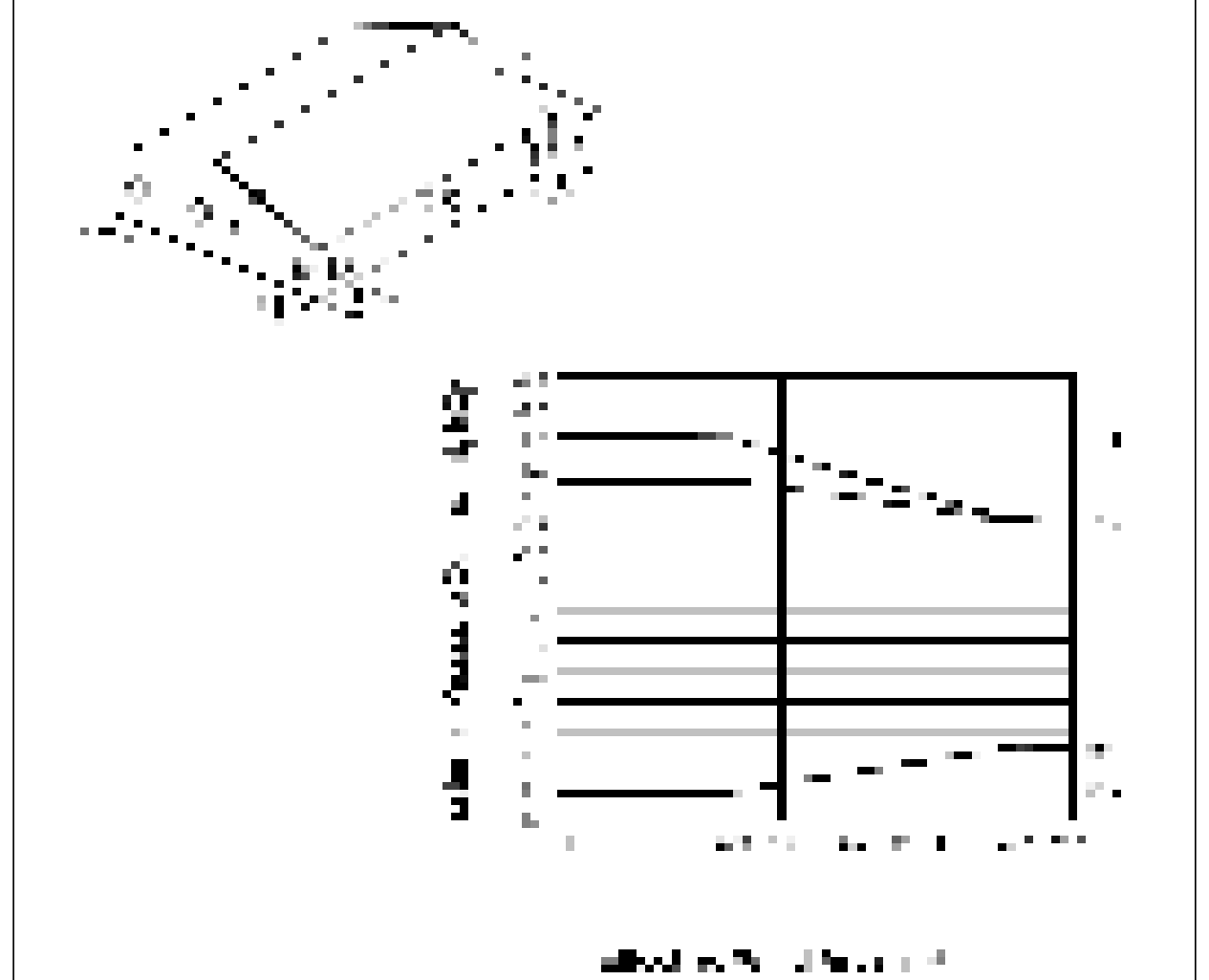
- Vertical scale denotes GCP to be used with qh.
- Horizontal scale denotes effective wind area, in square meters.
- Plus and minus signs signify pressures acting toward and away from the surfaces, respectively.
- Each component shall be designed for maximum positive and negative pressures.
- If a parapet equal to or higher than 0.9 m is provided around the perimeter of the roof with θ ≤ 70 , the negative values of GCp in Zone 3 shall be equal to those for Zone 2 and positive values of GCP in Zones 2 and 4 shall be set equal to those for wall Zones 4 and 5 respectively in Figure 6.2.11(a).
- Values of GCP for roof overhangs include pressure contributions from both upper and lower surfaces.
- Notation:
- a: 10 percent of least horizontal dimension or 0.4h , whichever is smaller, but not less than either 4% of least horizontal dimension or 0.9 m.
- h: Eave height shall be used for θ ≤ 100 .
- θ: Angle of plane of roof from horizontal, in degrees.
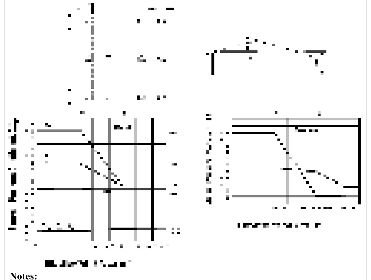
- Vertical scale denotes GCP to be used with q h
- Horizontal scale denotes effective wind area, in square feet (square meters).
- Plus and minus signs signify pressures acting toward and away from the surfaces, respectively.
- Each component shall be designed for maximum positive and negative pressures.
- Values of GCP for roof overhangs include pressure contributions from both upper and lower surfaces.
- For hip roofs with 70 < θ ≤ 270 , edge/ridge strips and pressure coefficients for ridges of gabled roofs shall apply on each hip.
- For hip roofs with 70 < θ ≤ 250 , Zone 3 shall be treated as Zone 2.
- Notation:
- a: 10 percent of least horizontal dimension or 0.4h, whichever is smaller, but not less than either 4% of least horizontal dimension or 0.9 m.
- h: Mean roof height, in meters, except that eave height shall be used for θ ≤ 100 .
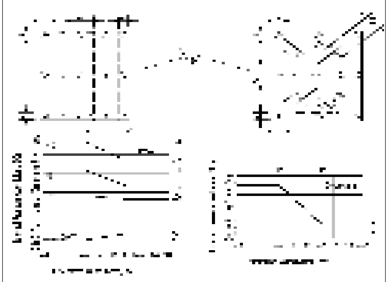
- Vertical scale denotes GCP to be used with qh. 2. Horizontal scale denotes effective wind area, in square feet (square meters).
- Plus and minus signs signify pressures acting toward and away from the surfaces, respectively.
- Each component shall be designed for maximum positive and negative pressures.
- Values of GCP for roof overhangs include pressure contributions from both upper and lower surfaces.
- Notation: a: 10 percent of least horizontal dimension or 0.4h, whichever is smaller, but not less than either 4% of least horizontal dimension or 0.9m.
- Vertical scale denotes GCP to be used with qh.
- Horizontal scale denotes effective wind area, in square meters.
- Plus and minus signs signify pressures acting toward and away from the surfaces, respectively.
- Each component shall be designed for maximum positive and negative pressures.
- For θ ≤ 100 Values of GCP from Figure 6.2.11 shall be used. 6. Notation:
- a: 10 percent of least horizontal dimension or 0.4 h , whichever is smaller, but not less than either 4% of least horizontal dimension or 0.9 m.
- h: Mean roof height, in feet (meters), except that eave height shall be used for θ ≤ 100 .
- θ: Angle of plane of roof from horizontal, in degrees.
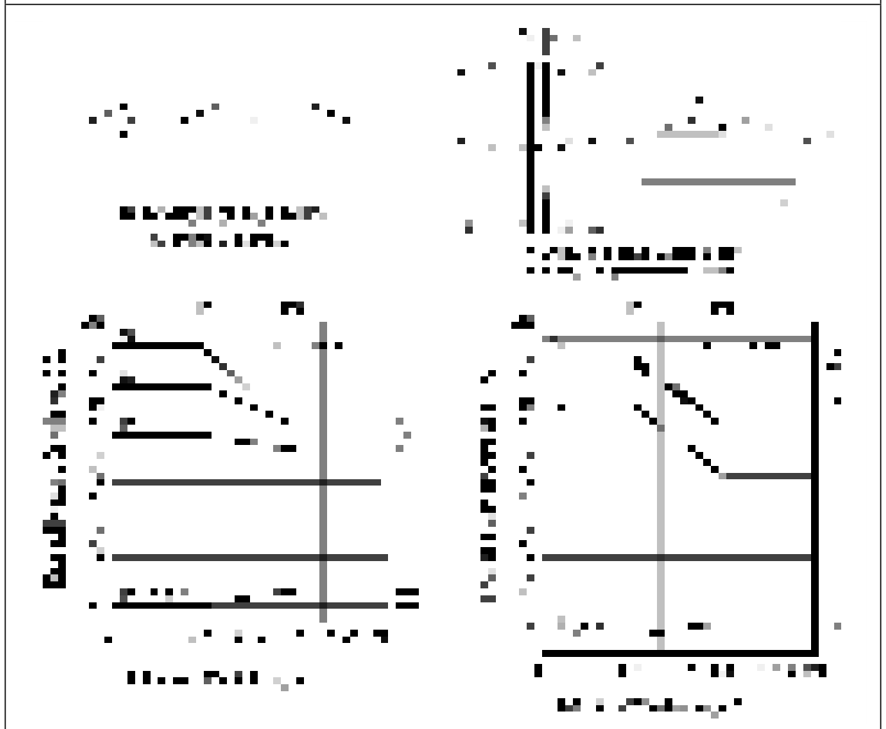
- Vertical scale denotes GCP to be used with qh.
- Horizontal scale denotes effective wind area A, in square meters.
- Plus and minus signs signify pressures acting toward and away from the surfaces, respectively.
- Each component shall be designed for maximum positive and negative pressures.
- For θ ≤ 30° Values of GCP from Figure 6.2.11(b) shall be used.
- Notation:
- a: 10 percent of least horizontal dimension or 0.4h, whichever is smaller, but not less than either 4% of least horizontal dimension or 0.9 m.
- h: Eave height shall be used for θ ≤ 100 .
- W: Building width, in meters.
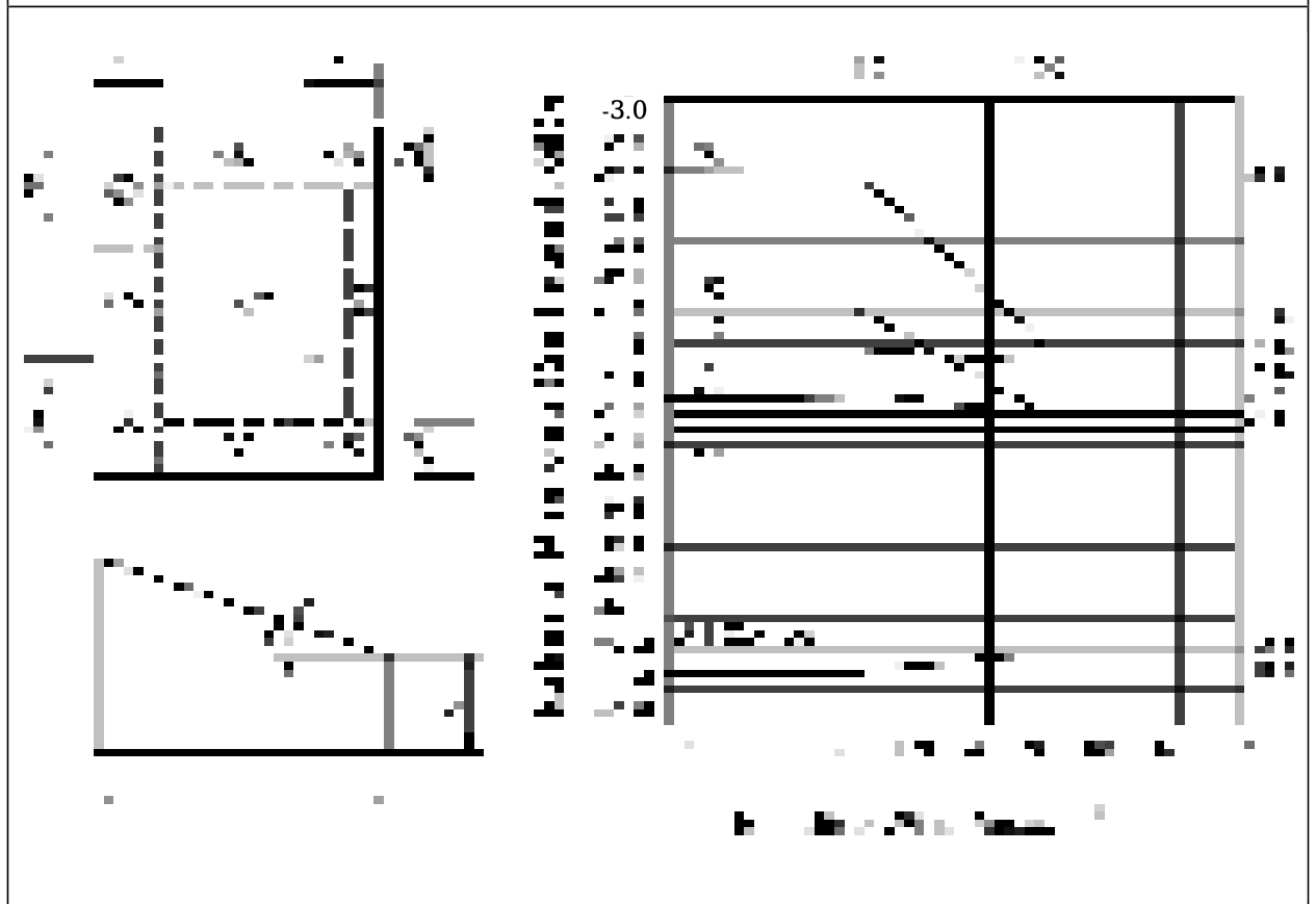
- Vertical scale denotes GCP to be used with qh
- Horizontal scale denotes effective wind area A, in square feet (square meters).
- Plus and minus signs signify pressures acting toward and away from the surfaces, respectively.
- Each component shall be designed for maximum positive and negative pressures.
- Notation:
- a: 10 percent of least horizontal dimension or 0.4h, whichever is smaller, but not less than either 4% of least horizontal dimension or 0.9 m.
- h: Mean roof height in meters.
- W: Building width, in meters.
- θ: Angle of plane of roof from horizontal, in degrees.
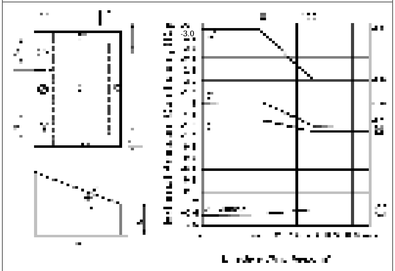
- Vertical scale denotes GCP to be used with qh.
- Horizontal scale denotes effective wind area A, in square feet (square meters).
- Plus and minus signs signify pressures acting toward and away from the surfaces, respectively.
- Each component shall be designed for maximum positive and negative pressures.
- For θ≤100 Values of GCP from Figure 6.2.11 shall be used.
- Notation:
- a: 10 percent of least horizontal dimension or 0.4h, whichever is smaller, but not less than either 4% of least horizontal dimension or 0.9 m.
- h: Mean roof height in meters except that eave height shall be used for θ≤ 100 . W: Building width, in meters.
- θ: Angle of plane of roof from horizontal, in degrees.
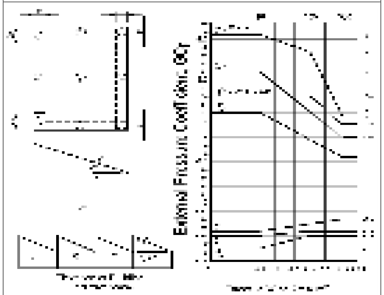
- Values denote Cp to be used with q(hD+f) where hD+f is the height at the top of the dome.
- Plus and minus signs signify pressures acting toward and away from the surfaces, respectively.
- Each component shall be designed for maximum positive and negative pressures.
- Values apply to θ ≤ hDD ≤ 0.5, 0.2≤ f/D ≤0.5.
- θ 50o on dome springline, θ 5 90o at dome center top point. f is measured from springline to top.
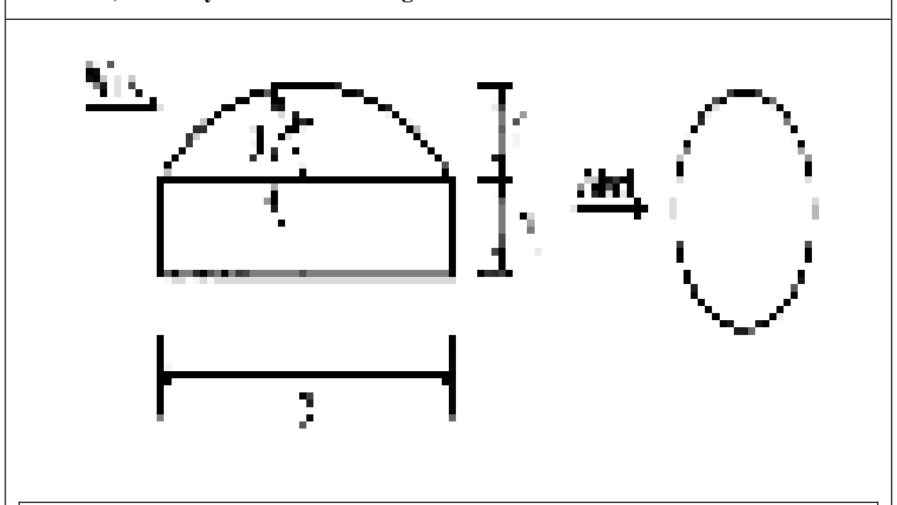
- 2.Horizontal scale denotes effective wind area _A in square feet (square meters).
- 3.Plus and minus signs signify pressures acting toward and away from the surfaces, respectively.
- 5.Each component shall be designed for maximum positive and negative pressures.
- 6.Coefficients are for roofs with angle θ≤10°. For other roof angles and geometry, use GCp values from Figure 6.2.11 and attendant qh based on exposure defined in Sec 2.4.6.
- 7.If a parapet equal to or higher than 0.9 m is provided around the perimeter of the roof with θ≤10° Zone 3 shall be treated as Zone 2.
- 8.Notation:
- h: Mean roof height, in meters, except that eave height shall be used for θ≤10o .
- z: height above ground, in (meters).
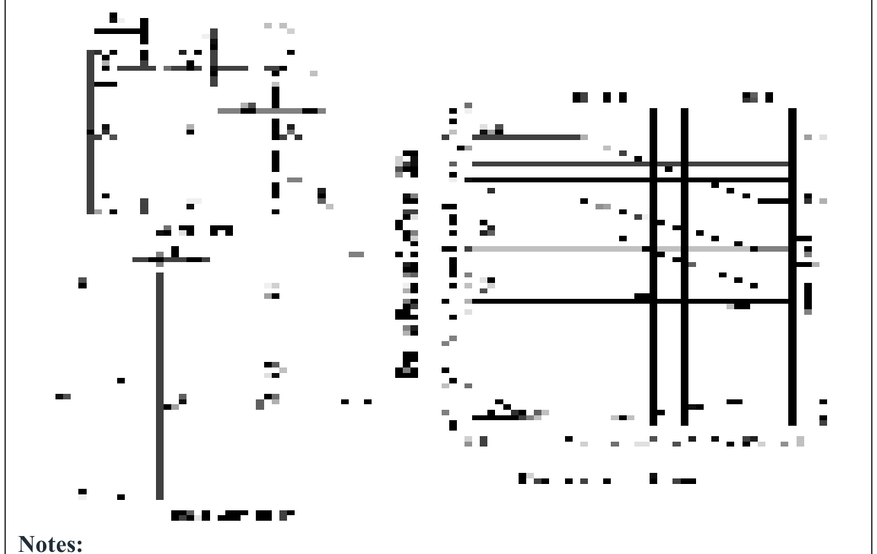
- CNW and CNL denote net pressures (contributions from top and bottom surfaces) for windward and leeward half of roof surfaces, respectively.
- Clear wind flow denotes relatively unobstructed wind flow with blockage less than or equal to 50%. Obstructed wind flow denotes objects below roof inhibiting wind flow (>50% blockage).
- For values of e between 7.5° and 45°, linear interpolation is permitted. For values of e less than 7.5°, use Monoslope roof load coefficients.
- Plus and minus signs signify pressures acting towards and away from the top roof surface, respectively.
- All load cases shown for each roof angle shall be investigated.
- Notation:
- h : mean roof height, m γ : direction of wind, degrees θ : angle of plane of roof from horizontal, degrees
- CNW and CNL denote net pressures (contributions from top and bottom surfaces) for windward and leeward half of roof surfaces, respectively.
- Clear wind flow denotes relatively unobstructed wind flow with blockage less than or equal to 50%. Obstructed wind flow denotes objects below roof inhibiting wind flow (>50% blockage).
- For values of θ between 7.5° and 45°, linear interpolation is permitted. For values of θ less than 7.5°, use monoslope roof load coefficients.
- Plus and minus signs signify pressures acting towards and away from the top roof surface, respectively.
- All load cases shown for each roof angle shall be investigated.
- Notation:
- h : mean roof height, m
- : angle of plane of roof from horizontal, degrees
- Notes: 1. CNW and CNL denote net pressures (contributions from top and bottom surfaces) for windward and leeward half of roof surfaces, respectively.
- Clear wind flow denotes relatively unobstructed wind flow with blockage less than or equal to 50%. Obstructed wind flow denotes objects below roof inhibiting wind flow (>50% blockage).
- For values of θ between 7.5° and 45°, linear interpolation is permitted. For values of θ less than 7.5°, use monoslope roof load coefficients.
- Plus and minus signs signify pressures acting towards and away from the top roof surface, respectively.
- All load cases shown for each roof angle shall be investigated.
- Notation:
- L : horizontal dimension of roof, measured in the along wind direction, m
- h : mean roof height, m
- γ : direction of wind, degrees θ : angle of plane of roof from horizontal, degrees
- CN denotes net pressures (contributions from top and bottom surfaces).
- Clear wind flow denotes relatively unobstructed wind flow with blockage less than or equal to 50%. Obstructed wind flow denotes objects below roof inhibiting wind flow (>50% blockage).
- Plus and minus signs signify pressures acting towards and away from the top roof surface, respectively.
- All load cases shown for each roof angle shall be investigated.
- For monoslope roofs with theta less than 5 degrees, CN values shown apply also for cases where gamma 5 0 degrees and 0.05 less than or equal to h/L less than or equal to 0.25. See Figure 6.2.18(a) for other h/L values.
- Notation:
- L : horizontal dimension of roof, measured in the along wind direction, m
- h : mean roof height, m
- : angle of plane of roof from horizontal, degrees
- CNdenotes net pressures (contributions from top and bottom surfaces).
- Clear wind flow denotes relatively unobstructed wind flow with blockage less than or equal to 50% wind flow denotes objects below roof inhibiting wind flow (>50% blockage).
- For values of e other than those shown, linear interpolation is permitted.
- Plus and minus signs signify pressures acting towards and away from the top roof surface, respectively.
- Components and cladding elements shall be designed for positive and negative pressure coefficients shown.
- Notation:
- : 10% of least horizontal dimension or 0.4h, whichever is smaller but not less than
- 4% of least horizontal dimension or 0.9 m h : mean roof height, m L : horizontal dimension of building, measured in along wind direction, m θ: angle of plane of roof from horizontal, degrees
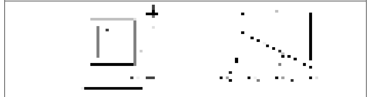
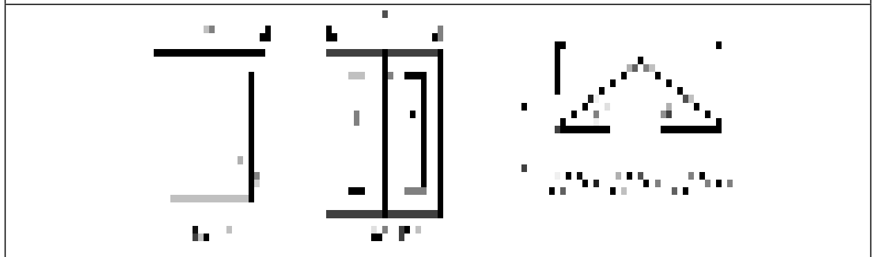

- The term “signs” in notes below also applies to “freestanding walls”.
- Signs with openings comprising less than 30% of the gross area are classified as solid signs. Force coefficients for solid signs with openings shall be permitted to be multiplied by the reduction factor (1 - (1 - ε)1.5 ).
- To allow for both normal and oblique wind directions, the following cases shall be considered:
- CASE A: resultant force acts normal to the face of the sign through the geometric center.
- For CASE C where s/h > 0.8, force coefficients shall be multiplied by the reduction factor (1.8 - s/h). 5. Linear interpolation is permitted for values of s/h, B/s and Lr/s other than shown. 6. Notation: B: horizontal dimension of sign, in meters; h : height of the sign, in meters; s: vertical dimension of the sign, in meters; ε: ratio of solid area to gross area; Lr: horizontal dimension of return corner, in meters
- The design wind force shall be calculated based on the area of the structure projected on a plane normal to the wind direction. The force shall be assumed to act parallel to the wind direction.
- Linear interpolation is permitted for h/D values other than shown.
- Notation:
- D : diameter of circular cross-section and least horizontal dimension of square, hexagonal or octagonal cross-section at elevation under consideration, in meters;
- D’: depth of protruding element such as ribs and spoilers, in meters;
- H: height of structure, meters and
- qz: velocity pressure evaluated at height z above ground, in N/m2
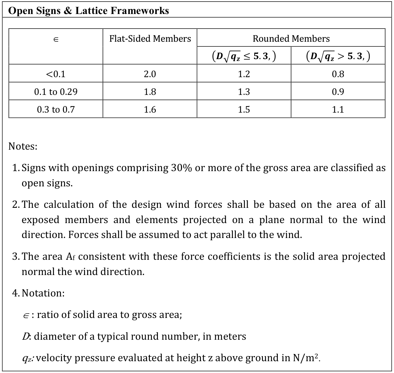
- Notes: 1. Signs with openings comprising 30% or more of the gross area are classified as open signs.
-
- The calculation of the design wind forces shall be based on the area of all exposed members and elements projected on a plane normal to the wind direction. Forces shall be assumed to act parallel to the wind.
-
- The area Af consistent with these force coefficients is the solid area projected normal the wind direction.
-
- Notation: ∈ : ratio of solid area to gross area; D: diameter of a typical round number, in meters qz: velocity pressure evaluated at height z above ground in N/m2 .
- For all wind directions considered, the area Af consistent with the specified force coefficients shall be the solid area of a tower face projected on the plane of that face for the tower segment under consideration.
- The specified force coefficients are for towers with structural angles or similar flat-sided members.
- For towers containing rounded members, it is acceptable to multiply the specified force coefficients by the following factor when determining wind forces on such members: 0.51 ∈2 + 0.57 ≤ 1.0
- Wind forces shall be applied in the directions resulting in maximum member forces and reactions. For towers with square cross-sections, wind forces shall be multiplied by the following factor when the wind is directed along a tower diagonal:
- Wind forces on tower appurtenances such as ladders, conduits, lights, elevators, etc., shall be calculated using appropriate force coefficients for these elements.
- Notation: ∈ : ratio of solid area to gross area of one tower face for the segment under consideration.
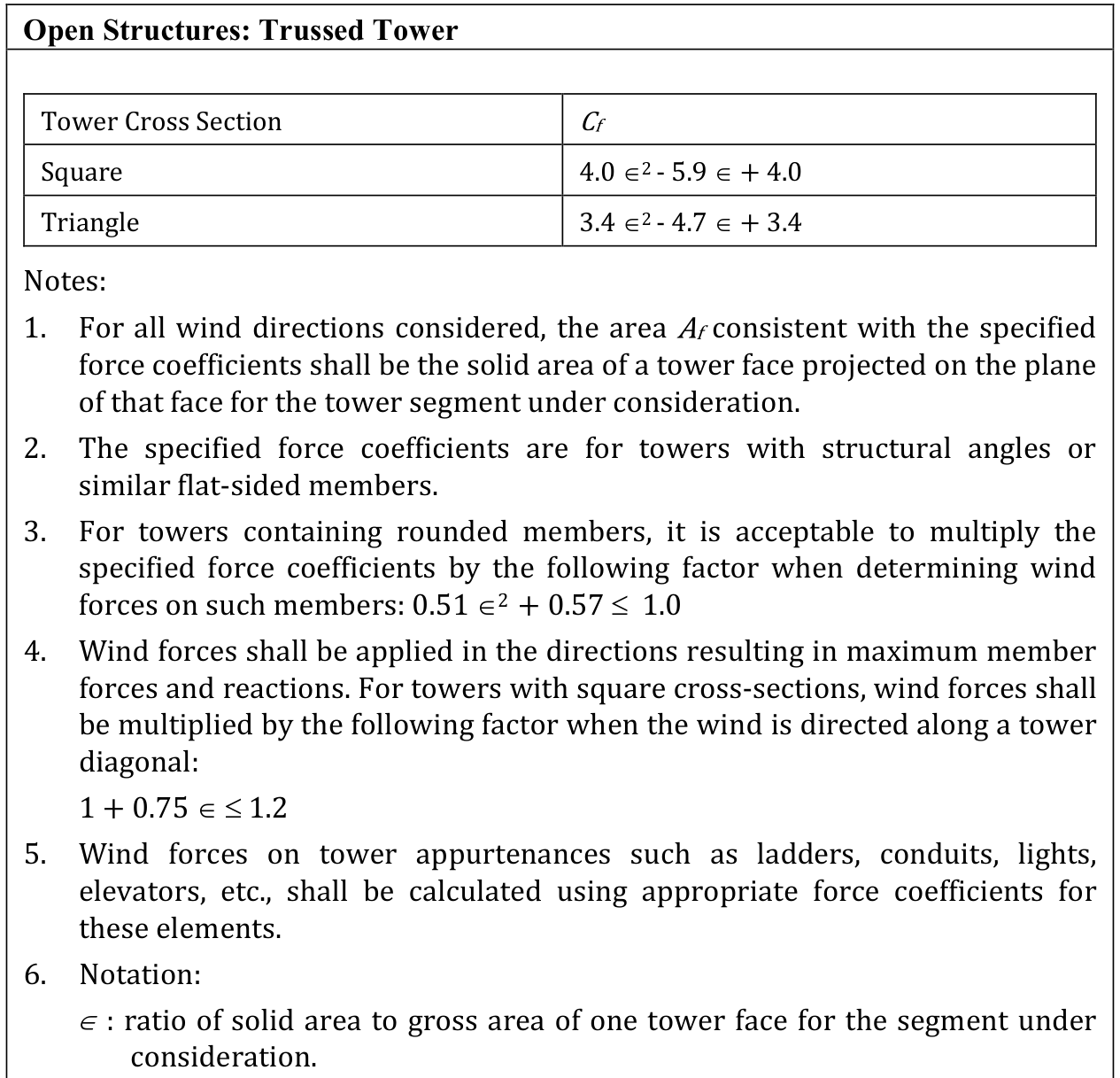
Table 6.2.10: Terrain Exposure Constants
Table 6.2.11: Velocity Pressure Exposure Coefficients, K_z and K_h
- Case 1:
- (a) All components and cladding.
- (b) Main wind force resisting system in low-rise buildings designed using Figure 6.2.10.
- (a) All main wind force resisting systems in buildings except those in lowrise buildings designed using Figure 6.2.10.
- (b) All main wind force resisting systems in other structures.
- The velocity pressure exposure coefficient may be determined from the following formula:
- and are tabulated in Table 6.2.10.
- Linear interpolation for intermediate values of height z is acceptable.
- Exposure categories are defined in Sec 2.4.6.3.
- Directionality Factor 0 has been calibrated with combinations of loads specified in Sec 2.7. This factor shall only be applied when used in conjunction with load combinations specified in Sections 2.7.2 and 2.7.3.
2.5 Earthquake Loads
2.5.1 General
Minimum design earthquake forces for buildings, structures or components thereof shall be determined in accordance with the provisions of Sec 2.5. Some definitions and symbols relevant for earthquake resistant design for buildings are provided in Sections 2.1.3 and 2.1.4. Section 2.5.2 presents basic earthquake resistant design concepts. Section 2.5.3 describes procedures for soil investigations, while Sec 2.5.4 describes procedures for determining earthquake ground motion for design. Section 2.5.5 describes different types of buildings and structural systems which possess different earthquake resistant characteristics. Static analysis procedures for design are described in Sections 2.5.6, 2.5.7 and 2.5.12. Dynamic analysis procedures are dealt with in Sections 2.5.8 to 2.5.11. Section 2.5.13 presents how seismic effects are accounted in the design and combination of earthquake loading effects in different directions and with other loading effects. Section 2.5.14 deals with allowable drift and deformation limits. Section 2.5.15 addresses design of non-structural components in buildings. Section 2.5.16 presents design considerations for buildings with seismic isolation systems. Design for soft storey condition in buildings is addressed in Sec 2.5.17.2.5.2 Earthquake Resistant Design – Basic Concepts
2.5.2.1 General principles
The purpose of earthquake resistant design provisions in this Code is to provide guidelines for the design and construction of new structures subject to earthquake ground motions in order to minimize the risk to life for all structures, to increase the expected performance of higher occupancy structures as compared to ordinary structures, and to improve the capability of essential structures to function after an earthquake. It is not economically feasible to design and construct buildings without any damage for a major earthquake event. The intent is therefore to allow inelastic deformation and structural damage at preferred locations in the structure without endangering structural integrity and to prevent structural collapse during a major earthquake. The seismic zoning map (Fig. 6.2.24) divides the country into four seismic zones with different expected levels of intensity of ground motion. Each seismic zone has a zone coefficient which provides expected peak ground acceleration values on rock/firm soil corresponding to the maximum considered earthquake (MCE). The design basis earthquake is taken as 2/3 of the maximum considered earthquake. The effects of the earthquake ground motion on the structure is expressed in terms of an idealized elastic design acceleration response spectrum, which depends on (a) seismic zone coefficient and local soil conditions defining ground motion and (b) importance factor and response reduction factor representing building considerations. The earthquake forces acting on the structure is reduced using the response modification/reduction factor R in order to take advantage of the inelastic energy dissipation due to inherent ductility and redundancy in the structure as well as material over-strength. The importance factor I increases design forces for important structures. The provisions of this Code for ductility and detailing need to be satisfied even for structures and members for which load combinations that do not contain the earthquake effect indicate larger demands than combinations including earthquake. The elastic deformations calculated under these reduced design forces are multiplied by the deflection amplification factor, to estimate the deformations likely to result from the design earthquake. The seismic design guidelines presented in this Section are based on the assumption that the soil supporting the structure will not liquefy, settle or slide due to loss of strength during the earthquake. Reinforced and prestressed concrete members shall be suitably designed to ensure that premature failure due to shear or bond does not occur. Ductile detailing of reinforced concrete members is of prime importance. In steel structures, members and their connections should be so proportioned that high ductility is obtained, avoiding premature failure due to elastic or inelastic buckling of any type. The building structure shall include complete lateral and vertical force-resisting systems capable of providing adequate strength, stiffness, and energy dissipation capacity to withstand the design ground motions within the prescribed limits of deformation and strength demand. The design ground motions shall be assumed to occur along any horizontal direction of a building structure. The adequacy of the structural systems shall be demonstrated through the construction of a mathematical model and evaluation of this model for the effects of design ground motions.2.5.2.2 Characteristics of Earthquake Resistant Buildings
The desirable characteristics of earthquake resistant buildings are described below: Structural simplicity, uniformity and plan symmetry is characterized by an even distribution of mass and structural elements which allows short and direct transmission of the inertia forces created in the distributed masses of the building to its foundation. A building configuration with symmetrical layout of structural elements of the lateral force resisting system, and well-distributed inplan, is desirable. Uniformity along the height of the building is also important, since it tends to eliminate the occurrence of sensitive zones where concentrations of stress or large ductility demands might cause premature collapse. Some basic guidelines are given below:- (i) With respect to the lateral stiffness and mass distribution, the building structure shall be approximately symmetrical in plan with respect to two orthogonal axes.
- (ii) Both the lateral stiffness and the mass of the individual storeys shall remain constant or reduce gradually, without abrupt changes, from the base to the top of a particular building.
- (iii)All structural elements of the lateral load resisting systems, such as cores, structural walls, or frames shall run without interruption from the foundations to the top of the building.
- (iv)An irregular building may be subdivided into dynamically independent regular units well separated against pounding of the individual units to achieve uniformity.
- (v) The length to breadth ratio (h 5 6’/6)) of the building in plan shall not be higher than 4, where 6’ and 6) are respectively the larger and smaller in plan dimension of the building, measured in orthogonal directions.
2.5.3 Investigation and Assessment of Site Conditions
2.5.3.1 Site investigation
Appropriate site investigations should be carried out to identify the ground conditions influencing the seismic action. The ground conditions at the building site should normally be free from risks of ground rupture, slope instability and permanent settlements caused by liquefaction or densification during an earthquake. The possibility of such phenomena should be investigated in accordance with standard procedures described in Chapter 3 of this Part. The intent of the site investigation is to classify the Site into one of types SA, SB, SC, SD, SE, S1 and S2 as defined in Sec 2.5.3.2. Such classification is based on site profile and evaluated soil properties (shear wave velocity, Standard Penetration Resistance, undrained shear strength, soil type). The site class is used to determine the effect of local soil conditions on the earthquake ground motion. For sites representing special soil type S1 or S2, site specific special studies for the ground motion should be done. Soil type S1, having very low shear wave velocity and low material damping, can produce anomalous seismic site amplification and soil-structure interaction effects. For S2 soils, possibility of soil failure should be studied. For a structure belonging to Seismic Design Category C or D (Sec 2.5.5.2), site investigation should also include determination of soil parameters for the assessment of the following:- (a) Slope instability.
- (b) Potential for Liquefaction and loss of soil strength.
- (c) Differential settlement.
- (d) Surface displacement due to faulting or lateral spreading.
- (e) Lateral pressures on basement walls and retaining walls due to earthquake ground motion.
2.5.3.2 Site classification
Site will be classified as type SA, SB, SC, SD, SE, S1 and S2 based on the provisions of this Section. Classification will be done in accordance with Table 6.2.13 based on the soil properties of upper 30 meters of the site profile. Average soil properties will be determined as given in the following equations: Where,- 5 Number of soil layers in upper 30 m
- 5 Thickness of layer
- 5 Shear wave velocity of layer
- : 5 Field (uncorrected) Standard Penetration Value for layer
-
- 5 Thickness of cohesive layer
- ZD 5 Undrained shear strength of cohesive layer
2.5.4 Earthquake Ground Motion
2.5.4.1 Regional seismicity
Bangladesh can be affected by moderate to strong earthquake events due to its proximity to the collision boundary of the Northeast moving Indian plate and Eurasian Plate. Strong historical earthquakes with magnitude greater than 7.0 have affected parts of Bangladesh in the last 150 years, some of them had their epicenters within the country. A brief description of the local geology, tectonic features and earthquake occurrence in the region is given in Appendix B.2.5.4.2 Seismic zoning
The intent of the seismic zoning map is to give an indication of the Maximum Considered Earthquake (MCE) motion at different parts of the country. In probabilistic terms, the MCE motion may be considered to correspond to having a 2% probability of exceedance within a period of 50 years. The country has been divided into four seismic zones with different levels of ground motion. Table 6.2.14 includes a description of the four seismic zones. Figure 6.2.24 presents a map of Bangladesh showing the boundaries of the four zones. Each zone has a seismic zone coefficient (Z) which represents the maximum considered peak ground acceleration (PGA) on very stiff soil/rock (site class SA) in units of g (acceleration due to gravity). The zone coefficients (Z) of the four zones are: Z50.12 (Zone 1), Z50.20 (Zone 2), Z50.28 (Zone 3) and Z50.36 (Zone 4). Table 6.2.15 lists zone coefficients for some important towns of Bangladesh. The most severe earthquake prone zone, Zone 4 is in the northeast which includes Sylhet and has a maximum PGA value of 0.36g. Dhaka city falls in the moderate seismic intensity zone with Z50.2, while Chittagong city falls in a severe intensity zone with Z50.28.2.5.4.3 Design response spectrum
The earthquake ground motion for which the building has to be designed is represented by the design response spectrum. Both static and dynamic analysis methods are based on this response spectrum. This spectrum represents the spectral acceleration for which the building has to be designed as a function of the building period, taking into account the ground motion intensity. The spectrum is based on elastic analysis but in order to account for energy dissipation due to inelastic deformation and benefits of structural redundancy, the spectral accelerations are reduced by the response modification factor R. For important structures, the spectral accelerations are increased by the importance factor I. The design basis earthquake (DBE) ground motion is selected at a ground shaking level that is 2/3 of the maximum considered earthquake (MCE) ground motion. The effect of local soil conditions on the response spectrum is incorporated in the normalized acceleration response spectrum Cs. The spectral acceleration for the design earthquake is given by the following equation: Where,- Design spectral acceleration (in units of ) which shall not be less than
- Coefficient used to calculate lower bound for . Recommended value for is 0.11
- Seismic zone coefficient, as defined in Sec 2.5.4.2
- Structure importance factor, as defined in Sec 2.5.5.1
- Response reduction factor which depends on the type of structural system given in Table 6.2.19. The ratio cannot be greater than one.
- Normalized acceleration response spectrum, which is a function of structure (building) period and soil type (site class) as defined by Equations 6.2.35a to 6.2.35d.
- S 5 Soil factor which depends on site class and is given in Table 6.2.16
- T 5 Structure (building) period as defined in Sec 2.5.7.2
- TB 5 Lower limit of the period of the constant spectral acceleration branch given in Table 6.2.16 as a function of site class.
- TC 5 Upper limit of the period of the constant spectral acceleration branch given in Table 6.2.16 as a function of site class
- TD 5 Lower limit of the period of the constant spectral displacement branch given in Table 6.2.16 as a function of site class
- = Damping correction factor as a function of damping with a reference value of for 5% viscous damping. It is given by the following expression:
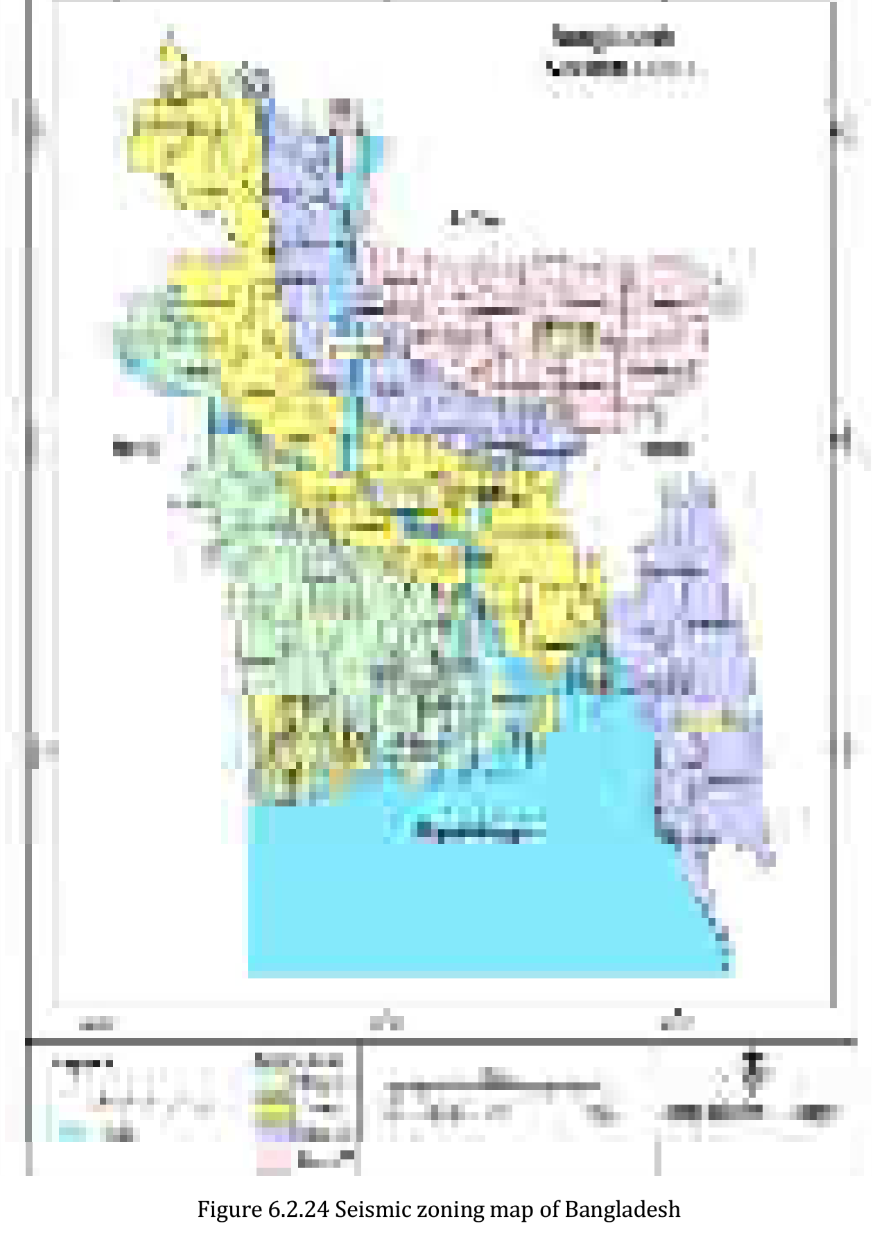
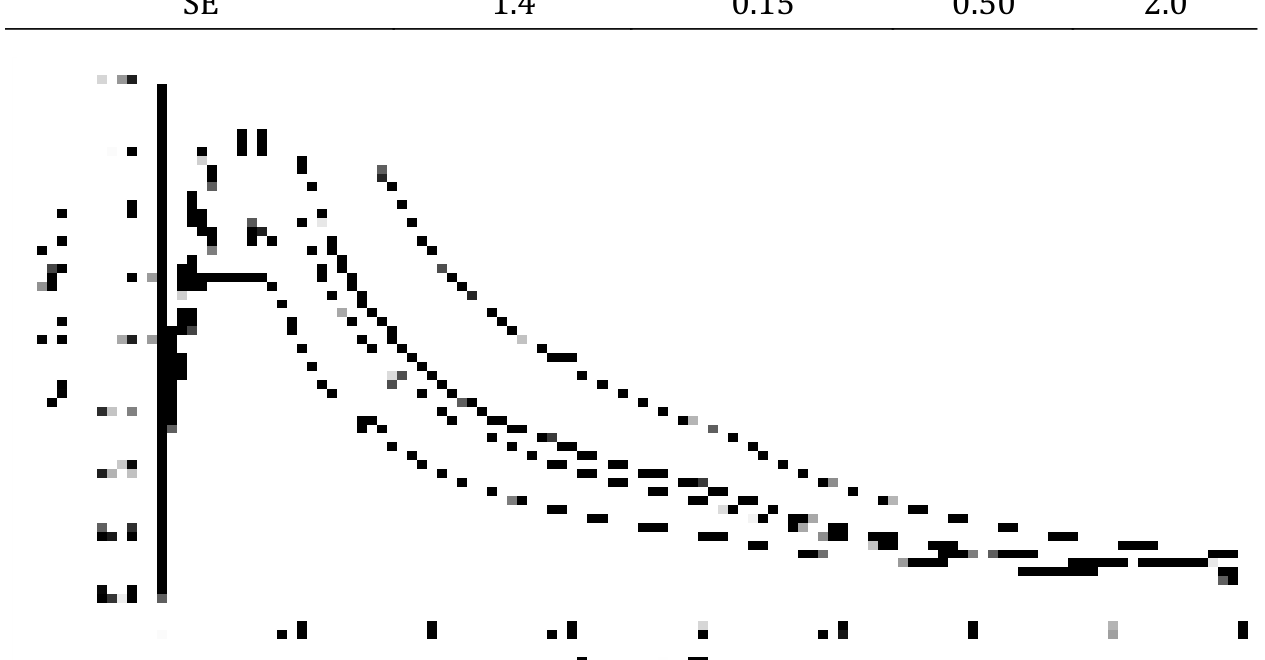
2.5.5 Building Categories
2.5.5.1 Importance factor
Buildings are classified in four occupancy categories in Chapter 1 (Table 6.1.1), depending on the consequences of collapse for human life, on their importance for public safety and civil protection in the immediate post-earthquake period, and on the social and economic consequences of collapse. Depending on occupancy category, buildings may be designed for higher seismic forces using importance factor greater than one. Table 6.2.17 defines different occupancy categories and corresponding importance factor. Table 6.2.17: Importance Factors for Buildings and Structures for Earthquake design2.5.5.2 Seismic design category
Buildings shall be assigned a seismic design category among B, C or D based on seismic zone, local site conditions and importance class of building, as given in Table 6.2.18. Seismic design category D has the most stringent seismic design detailing, while seismic design category B has the least seismic design detailing requirements. Table 6.2.18: Seismic Design Category of Buildings2.5.5.3 Building irregularity
Buildings with irregularity in plan or elevation suffer much more damage in earthquakes than buildings with regular configuration. A building may be considered as irregular, if at least one of the conditions given below are applicable:2.5.5.3.1
Plan irregularity: Following are the different types of irregularities that may exist in the plan of a building.- (i) Torsion irregularity
- (ii) Re-entrant corners
- (iii) Diaphragm Discontinuity
- (iv) Out- of-Plane Offsets
- (v) Non-parallel Systems
2.5.5.3.2
Vertical Irregularity: Following are different types of irregularities that may exist along vertical elevations of a building.- (i) Stiffness Irregularity - Soft Storey
- (ii) Mass Irregularity
- (iii) Vertical Geometric Irregularity
- This irregularity exists for buildings with setbacks with dimensions given in Figure [6.2.28(c)].
- (iv) Vertical In-Plane Discontinuity in Vertical Elements Resisting Lateral Force
- (v) Discontinuity in Capacity - Weak Storey
2.5.5.4 Type of structural systems
The basic lateral and vertical seismic force–resisting system shall conform to one of the types A to G indicated in Table 6.2.19. Each type is again subdivided by the types of vertical elements used to resist lateral seismic forces. A combination of systems may also be permitted as stated in Sec 2.5.5.5. The structural system to be used shall be in accordance with the seismic design category indicated in Table 6.2.18. Structural systems that are not permitted for a certain seismic design category are indicated by “NP”. Structural systems that do not have any height restriction are indicated by “NL”. Where there is height limit, the maximum height in meters is given. The response reduction factor, R, and the deflection amplification factor, indicated in Table 6.2.19 shall be used in determining the design base shear and design story drift. The selected seismic force-resisting system shall be designed and detailed in accordance with the specific requirements for the system. Seismic force resisting systems that are not given in Table 6.2.19 may be permitted if substantial analytical and test data are submitted that establish the dynamic characteristics and demonstrate the lateral force resistance and energy dissipation capacity to be equivalent to the structural systems listed in Table 6.2.19 for equivalent response modification coefficient, R, and deflection amplification factor, values.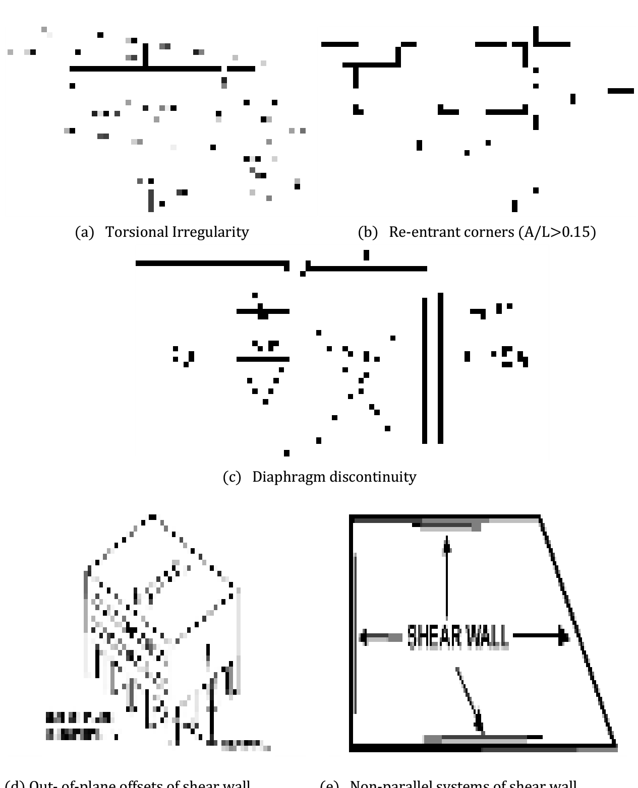
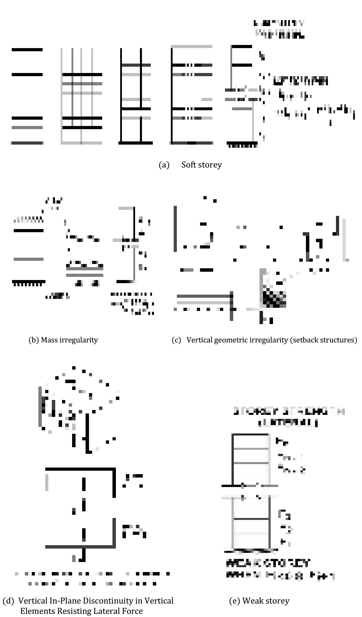
- (d) Vertical In-Plane Discontinuity in Vertical (e) Weak storey Elements Resisting Lateral Force
- Seismic design category, NL 5 No height restriction, NP 5 Not permitted. Number represents maximum allowable height (m).
- Dual Systems include buildings which consist of both moment resisting frame and shear walls (or braced frame) where both systems resist the total design forces in proportion to their lateral stiffness.
- See Sec. 10.20 of Chapter 10 of this Part for additional values of R and ” and height limits for some other types of steel structures not covered in this Table.
- Where data specific to a structure type is not available in this Table, reference may be made to Table 12.2-1 of ASCE 7-05.
2.5.5.5 Combination of structural systems
2.5.5.5.1
Combinations of Structural Systems in Different Directions: Different seismic force–resisting systems are permitted to be used to resist seismic forces along each of the two orthogonal axes of the structure. Where different systems are used, the respective R and coefficients shall apply to each system, including the limitations on system use contained in Table 6.2.19.2.5.5.5.2
Combinations of Structural Systems in the Same Direction: Where different seismic force–resisting systems are used in combination to resist seismic forces in the same direction of structural response, other than those combinations considered as dual systems, the more stringent system limitation contained in Table 6.2.19 shall apply. The value of R used for design in that direction shall not be greater than the least value of R for any of the systems utilized in that direction. The deflection amplification factor, in the direction under consideration at any story shall not be less than the largest value of this factor for the R factor used in the same direction being considered.2.5.5.6 Provisions for Using System Overstrength Factor, Ω
2.5.5.6.1 Combinations of Elements Supporting Discontinuous Walls or Frames.
Columns, beams, trusses, or slabs supporting discontinuous walls or frames of structures having horizontal irregularity Type IV of Table 6.1.5 or vertical irregularity Type IV of Table 6.1.4 shall have the design strength to resist the maximum axial force that can develop in accordance with the load combinations with overstrength factor of Section 2.5.13.4. The connections of such discontinuous elements to the supporting members shall be adequate to transmit the forces for which the discontinuous elements were required to be designed.2.5.5.6.2 Increase in Forces Due to Irregularities for Seismic Design Category D.
For structures assigned to Seismic Design Category D and having a horizontal structural irregularity of Type I.a, I.b, II, III, or IV in Table 6.1.5 or a vertical structural irregularity of Type IV in Table 6.1.4, the design forces determined from Section 2.5.7 shall be increased 25 percent for connections of diaphragms to vertical elements and to collectors and for connections of collectors to the vertical elements. Collectors and their connections also shall be designed for these increased forces unless they are designed for the load combinations with overstrength factor of Section 2.5.5.4, in accordance with Section 2.5.13.4.2.5.5.6.3 Collector Elements Requiring Load Combinations with Overstrength Factor for Seismic Design Categories C through D.
In structures assigned to Seismic Design Category C or D, collector elements, splices, and their connections to resisting elements shall resist the load combinations with overstrength of Section 2.5.13.4.2.5.5.6.4 Batter Piles.
Batter piles and their connections shall be capable of resisting forces and moments from the load combinations with overstrength factor of Section 2.5.13.4. Where vertical and batter piles act jointly to resist foundation forces as a group, these forces shall be distributed to the individual piles in accordance with their relative horizontal and vertical rigidities and the geometric distribution of the piles within the group.2.5.6 Static Analysis Procedure
Although analysis of buildings subjected to dynamic earthquake loads should theoretically require dynamic analysis procedures, for certain type of building structures subjected to earthquake shaking, simplified static analysis procedures may also provide reasonably good results. The equivalent static force method is such a procedure for determining the seismic lateral forces acting on the structure. This type of analysis may be applied to buildings whose seismic response is not significantly affected by contributions from modes higher than the fundamental mode in each direction. This requirement is deemed to be satisfied in buildings which fulfill the following two conditions:- (a) The building period in the two main horizontal directions is smaller than both 4TC (TC is defined in Sec 2.5.4.3) and 2 seconds.
- (b) The building does not possess irregularity in elevation as defined in Sec 2.5.5.3.
2.5.7 Equivalent Static Analysis
The evaluation of the seismic loads starts with the calculation of the design base shear which is derived from the design response spectrum presented in Sec 2.5.4.3. This Section presents different computations relevant to the equivalent static analysis procedure.2.5.7.1 Design base shear
The seismic design base shear force in a given direction shall be determined from the following relation: Where,- Lateral seismic force coefficient calculated using Eq. 6.2.34 (Sec 2.5.4.3). It is the design spectral acceleration (in units of g) corresponding to the building period (computed as per Sec 2.5.7.2).
- Total seismic weight of the building defined in Sec 2.5.7.3
2.5.7.2 Building period
The fundamental period T of the building in the horizontal direction under consideration shall be determined using the following guidelines:- (a) Structural dynamics procedures (such as Rayleigh method or modal eigenvalue analysis), using structural properties and deformation characteristics of resisting elements, may be used to determine the fundamental period T of the building in the direction under consideration. This period shall not exceed the approximate fundamental period determined by Eq. 6.2.38 by more than 40 percent.
- (b) The building period T (in sec) may be approximated by the following formula:
- Height of building in metres from foundation or from top of rigid basement. This excludes the basement storeys, where basement walls are connected with the ground floor deck or fitted between the building columns. But it includes the basement storeys, when they are not so connected. and are obtained from Table 6.2.20
- (c) For masonry or concrete shear wall structures, the approximate fundamental period, T (in sec) may be determined as follows:
- AB = area of base of structure hi = height of shear wall “i”
- Ai = web area of shear wall “i” Di = length of shear wall “i”
- x = number of shear walls in the building effective in resisting lateral forces in the direction under consideration.
2.5.7.3 Seismic weight
Seismic weight, W, is the total dead load of a building or a structure, including partition walls, and applicable portions of other imposed loads listed below:- (a) For live load up to and including 3 kN/m2 , a minimum of 25 percent of the live load shall be applicable.
- (b) For live load above 3 kN/m2 , a minimum of 50 percent of the live load shall be applicable.
- (c) Total weight (100 percent) of permanent heavy equipment or retained liquid or any imposed load sustained in nature shall be included.
2.5.7.4 Vertical distribution of lateral forces
In the absence of a more rigorous procedure, the total seismic lateral force at the base level, in other words the base shear V, shall be considered as the sum of lateral forces induced at different floor levels, these forces may be calculated as: Where, Part of base shear force induced at level x and Part of the total effective seismic weight of the structure (W) assigned to level i or x and the height from the base to level i or x For structure period ≤ 0.5s for structure period ≥ 2.5s linear interpolation between 1 and 2 for other periods. n 5 number of stories2.5.7.5 Storey shear and its horizontal distribution
The design storey shear , at any storey is the sum of the forces in that storey and all other stories above it, given by Eq. 6.2.42: Where, Portion of base shear induced at level i, as determined by Eq. 6.2.41. If the floor diaphragms can be considered to be infinitely rigid in the horizontal plane, the shear shall be distributed to the various elements of the lateral force resisting system in proportion to their relative lateral stiffness. For flexible diaphragms, the distribution of forces to the vertical elements shall account for the position and distribution of the masses supported. Allowance shall also be made for the increased shear arising due to horizontal torsional moment as specified in Sec 2.5.7.62.5.7.6 Horizontal torsional moments
Design shall accommodate increase in storey shear forces resulting from probable horizontal torsional moments on rigid floor diaphragms. Computation of such moments shall be as follows:2.5.7.6.1
In-built torsional effects: When there is in-built eccentricity between centre of mass and centre of rigidity (lateral resistance) at floor levels, rigid diaphragms at each level will be subject to torsional moment .2.5.7.6.2
Accidental torsional effects: In order to account for uncertainties in the location of masses and in the spatial variation of the seismic motion, accidental torsional effects need to be always considered. The accidental moment is determined assuming the storey mass to be displaced from the calculated centre of mass a distance equal to 5 percent of the building dimension at that level perpendicular to the direction of the force under consideration. The accidental torsional moment at level is given as: Where, eai = accidental eccentricity of floor mass at level i applied in the same direction at all floors floor dimension perpendicular to the direction of seismic force considered. Where torsional irregularity exists (Sec 2.5.5.3.1) for Seismic Design Category C or D, the irregularity effects shall be accounted for by increasing the accidental torsion at each level by a torsional amplification factor, as illustrated in Figure 6.2.29 determined from the following equation: Where, Maximum displacement at level-x computed assuming . Average displacements at extreme points of the building at level-x computed assuming . The accidental torsional moment need not be amplified for structures of lightframe construction. Also the torsional amplification factor () should not exceed 3.0.2.5.7.6.3
Design for torsional effects: The torsional design moment at a given storey shall be equal to the accidental torsional moment plus the inbuilt torsional moment (if any). Where earthquake forces are applied concurrently in two orthogonal directions, the required 5 percent displacement of the center of mass (for accidental torsion) need not be applied in both of the orthogonal directions at the same time, but shall be applied in only one direction that produces the greater effect.
2.5.7.7 Deflection and storey drift
The deflections () of level at the center of the mass shall be determined in accordance with the following equation: Where, Deflection amplification factor given in Table 6.2.19 Deflection determined by an elastic analysis Importance factor defined in Table 6.2.17 The design storey drift at storey shall be computed as the difference of the deflections at the centers of mass at the top and bottom of the story under consideration:2.5.7.8 Overturning effects
The structure shall be designed to resist overturning effects caused by the seismic forces determined in Sec 2.5.7.4. At any story, the increment of overturning moment in the story under consideration shall be distributed to the various vertical force resisting elements in the same proportion as the distribution of the horizontal shears to those elements. The overturning moments at level , shall be determined as follows: Where, Portion of the seismic base shear, induced at level Height from the base to level or . The foundations of structures, except inverted pendulum-type structures, shall be permitted to be designed for three-fourths of the foundation overturning design moment, determined using above equation.2.5.7.9 P-delta effects
The P-delta effects on story shears and moments, the resulting member forces and moments, and the story drifts induced by these effects are not required to be considered if the stability coefficient (θ) determined by the following equation is not more than 0.10: Where,- Total vertical design load at and above level ; where computing , no individual load factor need exceed 1.0
- Design story drift occurring simultaneously with
- Storey shear force acting between levels and
- Storey height below level
- Deflection amplification factor given in Table 6.2.19
2.5.8 Dynamic Analysis Methods
Dynamic analysis method involves applying principles of structural dynamics to compute the response of the structure to applied dynamic (earthquake) loads.2.5.8.1 Requirement for dynamic analysis
Dynamic analysis should be performed to obtain the design seismic force, and its distribution to different levels along the height of the building and to the various lateral load resisting elements, for the following buildings:- (a) Regular buildings with height greater than 40 m in Zones 2, 3, 4 and greater than 90 m in Zone 1.
- (b) Irregular buildings (as defined in Sec 2.5.5.3) with height greater than 12 m in Zones 2, 3, 4 and greater than 40 m in Zone 1.
2.5.8.2 Methods of analysis
Dynamic analysis may be carried out through the following two methods:- (i) Response Spectrum Analysis method is a linear elastic analysis method using modal analysis procedures, where the structure is subjected to spectral accelerations corresponding to a design acceleration response spectrum. The design earthquake ground motion in this case is represented by its response spectrum.
- (ii) Time History Analysis method is a numerical integration procedure where design ground motion time histories (acceleration record) are applied at the base of the structure. Time history analysis procedures can be two types: linear and non-linear.
2.5.9 Response Spectrum Analysis (RSA)
A response spectrum analysis shall consist of the analysis of a linear mathematical model of the structure to determine the maximum accelerations, forces, and displacements resulting from the dynamic response to ground shaking represented by the design acceleration response spectrum (presented in Sec 2.5.4.3). Response spectrum analysis is also called a modal analysis procedure because it considers different modes of vibration of the structure and combines effects of different modes.2.5.9.1 Modeling (RSA)
A mathematical model of the structure shall be constructed that represents the spatial distribution of mass and stiffness throughout the structure. For regular structures with independent orthogonal seismic-force-resisting systems, independent two-dimensional models are permitted to be constructed to represent each system. For irregular structures or structures without independent orthogonal systems, a three-dimensional model incorporating a minimum of three dynamic degrees of freedom consisting of translation in two orthogonal plan directions and torsional rotation about the vertical axis shall be included at each level of the structure. Where the diaphragms are not rigid compared to the vertical elements of the lateral-force-resisting system, the model should include representation of the diaphragm’s flexibility and such additional dynamic degrees of freedom as are required to account for the participation of the diaphragm in the structure’s dynamic response. The structure shall be considered to be fixed at the base or, alternatively, it shall be permitted to use realistic assumptions with regard to the stiffness of foundations. In addition, the model shall comply with the following:- (a) Stiffness properties of concrete and masonry elements shall consider the effects of cracked sections
- (b) The contribution of panel zone deformations to overall story drift shall be included for steel moment frame resisting systems.
2.5.9.2 Number of modes (RSA)
An analysis shall be conducted using the masses and elastic stiffnesses of the seismic-force-resisting system to determine the natural modes of vibration for the structure including the period of each mode, the modal shape vector k, the modal participation factor P and modal mass M. The analysis shall include a sufficient number of modes to obtain a combined modal mass participation of at least 90 percent of the actual mass in each of two orthogonal directions.2.5.9.3 Modal story shears and moments (RSA)
For each mode, the story shears, story overturning moments, and the shear forces and overturning moments in vertical elements of the structural system at each level due to the seismic forces shall be computed. The peak lateral force induced at level in mode is given by: Where,- = Design horizontal spectral acceleration corresponding to period of vibration of mode obtained from design response spectrum (Sec 2.5.4.3)
- = Modal participation factor of mode
- = Weight of floor .
2.5.9.4 Structure response (RSA)
In the response spectrum analysis method, the base shear ; each of the story shear, moment, and drift quantities; and the deflection at each level shall be determined by combining their modal values. The combination shall be carried out by taking the square root of the sum of the squares (SRSS) of each of the modal values or by the complete quadratic combination (CQC) technique. The complete quadratic combination shall be used where closely spaced periods in the translational and torsional modes result in cross-correlation of the modes. The distribution of horizontal shear shall be in accordance with the requirements of Sec 2.5.7.5. It should be noted that amplification of accidental torsion as per Sec 2.5.7.6 is not required where accidental torsional effects are included in the dynamic analysis model by offsetting the centre of mass in each story by the required amount. A base shear, shall also be calculated using the equivalent static force procedure in Sec 2.5.7. Where the base shear, is less than 85 percent of , all the forces but not the drifts obtained by response spectrum analysis shall be multiplied by the ratio . The displacements and drifts obtained by response spectrum analysis shall be multiplied by to obtain design displacements and drifts, as done in equivalent static analysis procedure (Sec 2.5.7.7). The P-delta effects shall be determined in accordance with Sec 2.5.7.9.2.5.10 Linear Time History Analysis (LTHA)
A linear time history analysis (LTHA) shall consist of an analysis of a linear mathematical model of the structure to determine its response, through direct numerical integration of the differential equations of motion, to a number of ground motion acceleration time histories compatible with the design response spectrum for the site. The analysis shall be performed in accordance with the provisions of this Section. For the purposes of analysis, the structure shall be permitted to be considered to be fixed at the base or, alternatively, it shall be permitted to use realistic assumptions with regard to the stiffness of foundations. The acceleration time history (ground motion) is applied at the base of the structure. The advantage of this procedure is that the time dependent behavior of the structural response is obtained.2.5.10.1 Modeling (LTHA)
Mathematical models shall conform to the requirements of modeling described in Sec 2.5.9.1.2.5.10.2 Ground motion (LTHA)
At least three appropriate ground motions (acceleration time history) shall be used in the analysis. Ground motion shall conform to the requirements of this Section. Two-dimensional analysis: Where two-dimensional analyses are performed, each ground motion shall consist of a horizontal acceleration time history selected from an actual recorded event. Appropriate acceleration histories shall be obtained from records of events having magnitudes, fault distance, and source mechanisms that are consistent with those that control the maximum considered earthquake. Where the required number of appropriate ground motion records are not available, appropriate simulated ground motion time histories shall be used to make up the total number required. The ground motions shall be scaled such that for each period between 0.2T and 1.5T (where T is the natural period of the structure in the fundamental mode for the direction considered) the average of the five-percent-damped response spectra for the each acceleration time history is not less than the corresponding ordinate of the design acceleration response spectrum, determined in accordance with Sec 2.5.4.3. Three-dimensional analysis: Where three-dimensional analysis is performed, ground motions shall consist of pairs of appropriate horizontal ground motion acceleration time histories (in two orthogonal horizontal directions) that shall be selected and scaled from individual recorded events. Appropriate ground motions shall be selected from events having magnitudes, fault distance, and source mechanisms that are consistent with those that control the maximum considered earthquake. Where the required number of recorded ground motion pairs are not available, appropriate simulated ground motion pairs shall be used to make up the total number required. For each pair of horizontal ground motion components, an SRSS spectrum shall be constructed by taking the square root of the sum of the squares of the five-percent-damped response spectra for the components (where an identical scale factor is applied to both components of a pair). Each pair of motions shall be scaled such that for each period between 0.2T and 1.5T (where T is the natural period of the fundamental mode of the structure) the average of the SRSS spectra from all horizontal component pairs is not less than 1.3 times the corresponding ordinate of the design response spectrum, determined in accordance with Sec 2.5.4.3.2.5.10.3 Structure response (LTHA)
For each scaled acceleration time history, the maximum values of base shear and other structure response quantities shall be obtained from the time history analysis. For three dimensional analysis, orthogonal pair of scaled motions are applied simultaneously. A base shear, , shall also be calculated using the equivalent static force procedure described in Sec 2.5.7.1. Where the maximum base shear, computed by linear time history analysis, is less than , all response quantities (storey shear, moments, drifts, floor deflections, member forces etc) obtained by time history analysis shall be increased by multiplying with the ratio, . If number of earthquake records (or pairs) used in the analysis is less than seven, the maximum structural response obtained corresponding to different earthquake records shall be considered as the design value. If the number is at least seven, then the average of maximum structural responses for different earthquake records shall be considered as the design value. The displacements and drifts obtained as mentioned above shall be multiplied +, by µ to obtain design displacements and drifts, as done in equivalent static analysis procedure (Sec 2.5.7.7).2.5.11 Non-Linear Time History Analysis (NTHA)
Nonlinear time history analysis (NTHA) shall consist of analysis of a mathematical model of the structure which incorporates the nonlinear hysteretic behavior of the structure’s components to determine its response, through methods of numerical integration, to ground acceleration time histories compatible with the design response spectrum for the site. The analysis shall be performed in accordance with the requirements of this Section. For the purposes of analysis, the structure shall be permitted to be considered to be fixed at the base or, alternatively, it shall be permitted to use realistic assumptions with regard to the stiffness of foundations. The acceleration time history (ground motion) is applied at the base of the structure. The advantage of this procedure is that actual time dependent behavior of the structural response considering inelastic deformations in the structure can be obtained.2.5.11.1 Modeling (NTHA)
A mathematical model of the structure shall be constructed that represents the spatial distribution of mass throughout the structure. The hysteretic behavior of elements shall be modeled consistent with suitable laboratory test data and shall account for all significant yielding, strength degradation, stiffness degradation, and hysteretic pinching indicated by such test data. Strength of elements shall be based on expected values considering material over-strength, strain hardening, and hysteretic strength degradation. As a minimum, a bilinear force deformation relationship should be used at the element level. In reinforced concrete and masonry buildings, the elastic stiffness should correspond to that of cracked sections. Linear properties, consistent with the provisions of Chapter 5 shall be permitted to be used for those elements demonstrated by the analysis to remain within their linear range of response. The structure shall be assumed to have a fixed base or, alternatively, it shall be permitted to use realistic assumptions with regard to the stiffness and load carrying characteristics of the foundations consistent with site-specific soils data and rational principles of engineering mechanics. For regular structures with independent orthogonal seismic-force-resisting systems, independent two dimensional models shall be permitted to be constructed to represent each system. For structures having plan irregularity or structures without independent orthogonal systems, a three-dimensional model incorporating a minimum of three dynamic degrees of freedom consisting of translation in two orthogonal plan directions and torsional rotation about the vertical axis at each level of the structure shall be used. Where the diaphragms are not rigid compared to the vertical elements of the lateral-force-resisting system, the model shall include representation of the diaphragm’s flexibility and such additional dynamic degrees of freedom as are required to account for the participation of the diaphragm in the structure’s dynamic response.2.5.11.2 Ground motion (NTHA)
The actual time-dependent inelastic deformation of the structure is modeled. For inelastic analysis method, the real design acceleration response spectrum (Sec 2.5.4.3) is obtained using Eq. 6.2.34 with R51 and I51. The real design acceleration response spectrum is the true representation of the expected ground motion (design basis earthquake) including local soil effects and corresponds to a peak ground acceleration (PGA) value of KC. 2 At least three appropriate acceleration time histories shall be used in the analysis. Ground motion shall conform to the requirements of this Section. Two-dimensional analysis Where two-dimensional analyses are performed, each ground motion shall consist of a horizontal acceleration time history selected from an actual recorded event. Appropriate acceleration histories shall be obtained from records of events having magnitudes, fault distance, and source mechanisms that are consistent with those that control the maximum considered earthquake. Where the required number of appropriate ground motion records are not available, appropriate simulated ground motion time histories shall be used to make up the total number required. The ground motions shall be scaled such that for each period between 0.2T and 1.5T (where T is the natural period of the structure in the fundamental mode for the direction considered) the average of the five-percent-damped response spectra for each acceleration time history is not less than the corresponding ordinate of the real design acceleration response spectrum, as defined here. Three-dimensional analysis Where three-dimensional analysis is performed, ground motions shall consist of pairs of appropriate horizontal ground motion acceleration time histories (in two orthogonal horizontal directions) that shall be selected and scaled from individual recorded events. Appropriate ground motions shall be selected from events having magnitudes, fault distance, and source mechanisms that are consistent with those that control the maximum considered earthquake. Where the required number of recorded ground motion pairs are not available, appropriate simulated ground motion pairs shall be used to make up the total number required. For each pair of horizontal ground motion components, an SRSS spectrum shall be constructed by taking the square root of the sum of the squares of the five-percent-damped response spectra for the components (where an identical scale factor is applied to both components of a pair). Each pair of motions shall be scaled such that for each period between 0.2T and 1.5T (where T is the natural period of the fundamental mode of the structure) the average of the SRSS spectra from all horizontal component pairs is not less than 1.3 times the corresponding ordinate of the real design acceleration response spectrum.2.5.11.3 Structure response (NTHA)
For each scaled acceleration time history, the maximum values of base shear and other structure response quantities shall be obtained from the nonlinear time history analysis. For three dimensional analysis, orthogonal pair of scaled motions are applied simultaneously. If number of earthquake records (or pairs) used in the analysis is less than seven, the maximum structural response obtained corresponding to different earthquake records shall be considered as the design value. If the number is at least seven, then the average of maximum structural responses for different earthquake records shall be considered as the design value. Since real expected earthquake motion input and model incorporating real nonlinear behavior of the structure is used, the results as obtained are directly used (no scaling as in LTHA or RSA is required) for interpretation and design.2.5.11.4 Structure member design (NTHA)
The adequacy of individual members and their connections to withstand the design deformations predicted by the analyses shall be evaluated based on laboratory test data for similar components. The effects of gravity and other loads on member deformation capacity shall be considered in these evaluations. Member deformation shall not exceed two thirds of the smaller of: the value that results in loss of ability to carry gravity loads or the value at which member strength has deteriorated to less than 67 percent of peak strength.2.5.11.5 Design review (NTHA)
Special care and expertise is needed in the use of nonlinear dynamic analysis based design. Checking of the design by competent third party is recommended. A review of the design of the seismic-force-resisting system and the supporting structural analyses shall be performed by an independent team consisting of design professionals with experience in seismic analysis methods and the theory and application of nonlinear seismic analysis and structural behavior under extreme cyclic loads. The design review shall include the following: (i) Review of development of ground motion time histories (ii) Review of acceptance criteria (including laboratory test data) used to demonstrate the adequacy of structural elements and systems to withstand the calculated force and deformation demands (iii) Review of structural design.2.5.12 Non-Linear Static Analysis (NSA)
Nonlinear static analysis (NSA), also popularly known as pushover analysis, is a simplified method of directly evaluating nonlinear response of structures to strong earthquake ground shaking. It is an alternative to the more complex nonlinear time history analysis (NTHA). The building is subjected to monotonically increasing static horizontal loads under constant gravity load.2.5.12.1 Modeling (NSA)
A mathematical model of the structure shall be constructed to represent the spatial distribution of mass and stiffness of the structural system considering the effects of element nonlinearity for deformation levels that exceed the proportional limit. P-Delta effects shall also be included in the analysis. For regular structures with independent orthogonal seismic-force-resisting systems, independent two-dimensional models may be used to represent each system. For structures having plan irregularities or structures without independent orthogonal systems, a three-dimensional model incorporating a minimum of three degrees of freedom for each level of the structure, consisting of translation in two orthogonal plan directions and torsional rotation about the vertical axis, shall be used. Where the diaphragms are not rigid compared to the vertical elements of the seismic-force-resisting system, the model should include representation of the diaphragm flexibility. Unless analysis indicates that an element remains elastic, a nonlinear force deformation model shall be used to represent the stiffness of the element before onset of yield, the yield strength, and the stiffness properties of the element after yield at various levels of deformation. Strengths of elements shall not exceed expected values considering material over-strength and strain hardening. The properties of elements and components after yielding shall account for strength and stiffness degradation due to softening, buckling, or fracture as indicated by principles of mechanics or test data. A control point shall be selected for the model. For normal buildings, the control point shall be at the center of mass of the highest level (roof) of the structure.2.5.12.2 Analysis procedure (NSA)
The lateral forces shall be applied at the center of mass of each level and shall be proportional to the distribution obtained from a modal analysis for the fundamental mode of response in the direction under consideration. The lateral loads shall be increased incrementally in a monotonic manner. At the increment of lateral loading, the total lateral force applied to the model shall be characterized by the term . The incremental increases in applied lateral force should be in steps that are sufficiently small to permit significant changes in individual element behavior (such as yielding, buckling or failure) to be detected. The first increment in lateral loading shall result in linear elastic behavior. At each loading step, the total applied lateral force, the lateral displacement of the control point, and the forces and deformations in each element shall be recorded. The analysis shall be continued until the displacement of the control point is at least 150 percent of the target displacement determined in accordance with Sec.2.5.12.3. The structure shall be designed so that the total applied lateral force does not decrease in any load increment for control point displacements less than or equal to 125 percent of the target displacement.2.5.12.3 Effective period and target displacement (NSA)
A bilinear curve shall be fitted to the capacity curve, such that the first segment of the bilinear curve coincides with the capacity curve at 60 percent of the effective yield strength, the second segment coincides with the capacity curve at the target displacement, and the area under the bilinear curve equals the area under the capacity curve, between the origin and the target displacement. The effective yield strength, corresponds to the total applied lateral force at the intersection of the two line segments. The effective yield displacement, corresponds to the control point displacement at the intersection of the two line segments. The effective fundamental period, of the structure in the direction under consideration shall be determined using Eq. 6.2.51 as follows: Where, , , and are determined for the first increment of lateral load. The target displacement of the control point, shall be determined as follows: Where, the spectral acceleration, , is determined at the effective fundamental period, , using Eq. 6.2.34, is the acceleration due to gravity. The coefficient shall be calculated as : Where, = the portion of the seismic weight, W, at level i, and = the amplitude of the shape vector at level i. Where the effective fundamental period, , is greater than (defined in Sec. 2.5.4.3), the coefficient shall be taken as 1.0. Otherwise, the value of the coefficient shall be calculated as follows: Where, is given as follows:2.5.12.4 Structure member design (NSA)
For each nonlinear static analysis the design response parameters, including the individual member forces and member deformations shall be taken as the values obtained from the analysis at the step at which the target displacement is reached. The adequacy of individual members and their connections to withstand the member forces and member deformations shall be evaluated based on laboratory test data for similar components. The effects of gravity and other loads on member deformation capacity shall be considered in these evaluations. The deformation of a member supporting gravity loads shall not exceed (i) twothirds of the deformation that results in loss of ability to support gravity loads, and (ii) two-thirds of the deformation at which the member strength has deteriorated to less than 70 percent of the peak strength of the component model. The deformation of a member not required for gravity load support shall not exceed two-thirds of the value at which member strength has deteriorated to less than 70 percent of the peak strength of the component model.2.5.12.5 Design review (NSA)
Checking of the design by competent third party is recommended. An independent team composed of at least two members with experience in seismic analysis methods and the theory and application of nonlinear seismic analysis and structural behavior under earthquake loading, shall perform a review of the design of the seismic force resisting system and the supporting structural analyses. The design review shall include (i) review of any sitespecific seismic criteria (if developed) employed in the analysis (ii) review of the determination of the target displacement and effective yield strength of the structure (iii) review of adequacy of structural elements and systems to withstand the calculated force and deformation demands, together with laboratory and other data (iv) review of structural design.2.5.13 Earthquake Load Effects and Load Combinations
The seismic load effect, E, shall be determined in accordance with the following:- For use in load combination 5 in Section 2.7.3 or load combination 5 and 6 in Section 2.7.2, E shall be determined in accordance with the following equation,
- For use in load combination 7 in Section 2.7.3 or load combination 8 in Section 2.7.2, E shall be determined in accordance with following equation, E 5 Eh − Ev
2.5.13.1 Horizontal earthquake loading, Eh
The horizontal seismic load effect, Eh, shall be taken as the horizontal load effects of seismic base shear V (Sec 2.5.7 or 2.5.9) or component forces Fc (Sec 2.5.15). The directions of application of horizontal seismic forces for design shall be those which will produce the most critical load effects. Earthquake forces act in both principal directions of the building simultaneously. In order to account for that,- (a) For structures of Seismic Design Category B, the design horizontal seismic forces are permitted to be applied independently in each of two orthogonal directions and orthogonal interaction effects are permitted to be neglected
- (b) Structures of Seismic Design Category C and D shall, as a minimum, conform to the requirements of (a) for Seismic Design Category B and in addition the requirements of this Section. The structure of Seismic Design Category C with plan irregularity type V and Seismic Design Category D shall be designed for 100% of the horizontal seismic forces in one principal direction combined with 30% of the horizontal seismic forces in the orthogonal direction. Possible combinations are:
- “±100% in x-direction ±30% in y-direction” or
- (c) Where three-dimensional analysis of a spatial structure model is performed as in 3D time history analysis, simultaneous application of accelerations in two directions shall be considered where the ground motions shall satisfy the conditions stated in Sections 2.5.10.2 or 2.5.11.2.
2.5.13.2 Vertical earthquake loading, Ev
The maximum vertical ground acceleration shall be taken as 50 percent of the expected horizontal peak ground acceleration (PGA). The vertical seismic load effect %¼ may be determined as: %¼ 5 0.50(L3)# (6.2.56) Where,- L3 5 expected horizontal peak ground acceleration (in g) for design 5 (2/3)KC
-
5 effect of dead load, S 5 site dependent soil factor (see Table 6.2.16).
2.5.13.3 Combination of earthquake loading with other loadings
When earthquake effect is included in the analysis and design of a building or structure, the provisions set forth in Sec 2.7 shall be followed to combine earthquake load effects, both horizontal and vertical, with other loading effects to obtain design forces etc.2.5.13.4 Seismic Load Effect Including Overstrength Factor
Where specifically required, conditions requiring overstrength factor, Ωo, applications shall be determined in accordance with the following,- For use in load combination 5 in Section 2.7.3 or load combinations 5 and 6 in Section 2.7.2, E shall be taken equal to Em as determined in accordance with the following equation,
- For use in load combination 7 in Section 2.7.3 or load combination 8 in Section 2.7.2, E shall be taken equal to Em as determined in accordance with the following equation,
- Emh 5 effect of horizontal seismic forces as defined in Sections 2.5.7 or 2.5.9 including structural overstrength.
- Ev 5 effect of vertical seismic forces as defined in Section 2.5.13.2
2.5.13.5 Allowable Stress Increase for Load Combinations with Overstrength
Where allowable stress design methodologies are used with the seismic load effect defined in Section 2.5.13.4 applied in load combinations 5, 6, or 8 of Section 2.7.2, allowable stresses are permitted to be determined using an allowable stress increase of 1.2. This increase shall not be combined with increases in allowable stresses or load combination reductions otherwise permitted elsewhere by this standard.2.5.13.6 Minimum Upward Force for Horizontal Cantilevers for Seismic Design Category D
In structures assigned to Seismic Design Category D, horizontal cantilever structural components shall be designed for a minimum net upward force of 0.2 times the dead load in addition to the applicable load combinations of Section 2.7.2.5.14 Drift and Deformation
2.5.14.1 Storey drift limit
The design storey drift (Δ) of each storey, as determined in Sections 2.5.7, 2.5.9 or 2.5.10 shall not exceed the allowable storey drift (Δa) as obtained from Table 6.2.21 for any story. For structures with significant torsional deflections, the maximum drift shall include torsional effects. For structures assigned to Seismic Design Category C or D having torsional irregularity, the design storey drift, shall be computed as the largest difference of the deflections along any of the edges of the structure at the top and bottom of the storey under consideration. For seismic force–resisting systems comprised solely of moment frames in Seismic Design Categories D, the allowable storey drift for such linear elastic analysis procedures shall not exceed Δ’/. where . is termed as a structural redundancy factor. The value of redundancy factor . may be considered as 1.0 with exception of structures of very low level of redundancy where . may be considered as 1.3. For nonlinear time history analysis (NTHA), the storey drift obtained (Sec 2.5.11) shall not exceed 1.25 times the storey drift limit specified above for linear elastic analysis procedures.2.5.14.2 Diaphragm deflection
The deflection in the plane of the diaphragm, as determined by engineering analysis, shall not exceed the permissible deflection of the attached elements. Permissible deflection shall be that deflection that will permit the attached element to maintain its structural integrity under the individual loading and continue to support the prescribed loads. Table 6.2.21: Allowable Storey Drift Limit ( /ú )- 1.ℎis the story height below Level .
- 2.There shall be no drift limit for single-story structures with interior walls, partitions, ceilings, and exterior wall systems that have been designed to accommodate the storey drifts.
- 3.Structures in which the basic structural system consists of masonry shear walls designed as vertical elements cantilevered from their base or foundation support which are so constructed that moment transfer between shear walls (coupling) is negligible.
- 4.Occupancy categories are defined in Table 6.1.1
2.5.14.3 Separation between adjacent structures
Buildings shall be protected from earthquake-induced pounding from adjacent structures or between structurally independent units of the same building maintaining safe distance between such structures as follows:- (i) for buildings, or structurally independent units, that do not belong to the same property, the distance from the property line to the potential points of impact shall not be less than the computed maximum horizontal displacement (Sec 2.5.7.7) of the building at the corresponding level.
- (ii) for buildings, or structurally independent units, belonging to the same property, if the distance between them is not less than the square root of the sum of the squares (SRSS) of the computed maximum horizontal displacements (Sec 2.5.7.7) of the two buildings or units at the corresponding level.
- (iii) if the floor elevations of the building or independent unit under design are the same as those of the adjacent building or unit, the above referred minimum distance may be reduced by a factor of 0.7
2.5.14.4 Special deformation requirement for seismic design category D
For structures assigned to Seismic Design Category D, every structural component not included in the seismic force–resisting system in the direction under consideration shall be designed to be adequate for the gravity load effects and the seismic forces resulting from displacement to the design story drift (Δ) as determined in accordance with Sec 2.5.7.7. Even where elements of the structure are not intended to resist seismic forces, their protection may be important. Where determining the moments and shears induced in components that are not included in the seismic force–resisting system in the direction under consideration, the stiffening effects of adjoining rigid structural and nonstructural elements shall be considered and a rational value of member and restraint stiffness shall be used.2.5.15 Seismic Design For Nonstructural Components
This Section establishes minimum design criteria for nonstructural components that are permanently attached to structures and for their supports and attachments. The following components are exempt from the requirements of this Section.- (1) Architectural components in Seismic Design Category B, other than parapets supported by bearing walls or shear walls, where the component importance factor, .+ is equal to 1.0.
- (2) Mechanical and electrical components in Seismic Design Category B.
- (3) Mechanical and electrical components in Seismic Design Category C where the importance factor, .+ is equal to 1.0.
- (4) Mechanical and electrical components in Seismic Design Category D where the component importance factor, .+ is equal to 1.0 and either (a) flexible connections between the components and associated ductwork, piping, and conduit are provided, or (b) components are mounted at 1.2 m or less above a floor level and weigh 1780 N or less.
- (5) Mechanical and electrical components in Seismic Design Category C or D where the component importance factor, .+ is equal to 1.0 and (a) flexible connections between the components and associated ductwork, piping, and conduit are provided, and (b) the components weigh 89 N or less or, for distribution systems, which weigh 73 N/m or less.
2.5.15.1 Component importance factor
All components shall be assigned a component importance factor. The component importance factor, .+ shall be taken as 1.5 if any of the following conditions apply:- (1) The component is required to function after an earthquake,
- (2) The component contains hazardous materials, or
- (3) The component is in or attached to a occupancy category IV building and it is needed for continued operation of the facility.
2.5.15.2 Component force transfer
Components shall be attached such that the component forces are transferred to the structure. Component attachments that are intended to resist seismic forces shall be bolted, welded, or otherwise positively fastened without consideration of frictional resistance produced by the effects of gravity. A continuous load path of sufficient strength and stiffness between the component and the supporting structure shall be verified. Local elements of the supporting structure shall be designed for the component forces where such forces control the design of the elements or their connections. In this instance, the component forces shall be those determined in Sec 2.5.15.3, except that modifications to &! and @! due to anchorage conditions need not be considered. The design documents shall include sufficient information concerning the attachments to verify compliance with the requirements of these Provisions.2.5.15.3 Seismic design force
The seismic design force, Fc, applied in the horizontal direction shall be centered at the component’s center of gravity and distributed relative to the component’s mass distribution and shall be determined as follows: Where, 0.75L3I+.+ ≤&+ ≤1.5L3I+.+ a+ 5 component amplification factor which varies from 1.0 to 2.5 (Table 6.2.22 or Table 6.2.23). L3 5 expected horizontal peak ground acceleration (in g) for design 5 0.67ZS I+ 5 weight of component @+ 5 component response reduction factor which varies from 1.0 to 12.0 (Table 6.2.22 or Table 6.2.23) 4 5 height above the base of the point of attachment of the component, but z shall not be taken less than 0 and the value of 4/ℎ need not exceed 1.0 h 5 roof height of structure above the base The force &+ shall be independently applied in at least two orthogonal horizontal directions in combination with service loads associated with the component. In addition, the component shall also be designed for a concurrent vertical force of ± 0.5ahWc. Where non-seismic loads on nonstructural components exceed &+ such loads shall govern the strength design, but the seismic detailing requirements and limitations shall apply.2.5.15.4 Seismic relative displacements
The relative seismic displacement, #+ for two connection points on the same structure A, one at a height ℎ and other at height ℎH, for use in component design shall be determined as follows: shall not exceed #+ ’ given by: Where,- w 5 Deflection at level x of structure A
- Hw 5 Deflection at level y of structure A
- ∆‘w 5 Allowable story drift for structure A
- hx = Height (above base) of level x to which upper connection point is attached.
- hy = Height (above base) of level y to which lower connection point is attached.
- hsx = Story height used in the definition of the allowable drift Δa
- HA = Deflection at level y of structure B
- ∆‘A = Allowable story drift for structure B
2.5.16 Design For Seismically Isolated Buildings
Buildings that use special seismic isolation systems for protection against earthquakes shall be called seismically isolated or base isolated buildings. Seismically isolated structure and every portion thereof shall be designed and constructed in accordance with the requirements of provisions presented in this Section.2.5.16.1 General requirements for isolation system
The isolation system to be used in seismically isolated structures shall satisfy the following requirements:- (1) Design of isolation system shall consider variations in seismic isolator material properties over the projected life of structure including changes due to ageing, contamination, exposure to moisture, loadings, temperature, creep, fatigue, etc.
- (2) Isolated structures shall resist design wind loads at all levels above the isolation interface. At the isolation interface, a wind restraint system shall be provided to limit lateral displacement in the isolation system to a value equal to that required between floors of the structure above the isolation interface.
- (3) The fire resistance rating for the isolation system shall be consistent with the requirements of columns, walls, or other such elements in the same area of the structure.
- (4) The isolation system shall be configured to produce a lateral restoring force such that the lateral force at the total design displacement is at least 0.025 W greater than the lateral force at 50% of the total design displacement.
- (5) The isolation system shall not be configured to include a displacement restraint that limits lateral displacement due to the maximum considered earthquake to less than the total maximum displacement unless it is demonstrated by analysis that such engagement of restraint does not result in unsatisfactory performance of the structure.
- (6) Each element of the isolation system shall be designed to be stable under the design vertical load when subjected to a horizontal displacement equal to the total maximum displacement.
- (7) The factor of safety against global structural overturning at the isolation interface shall not be less than 1.0 for required load combinations. All gravity and seismic loading conditions shall be investigated. Seismic forces for overturning calculations shall be based on the maximum considered earthquake and the vertical restoring force shall be based on the seismic weight above the isolation interface.
- (8) Local uplift of individual units of isolation system is permitted if the resulting deflections do not cause overstress or instability of the isolator units or other elements of the structure.
- (9) Access for inspection and replacement of all components of the isolation system shall be provided.
- (10) The designer of the isolation system shall establish a quality control testing program for isolator units. Each isolator unit before installation shall be tested under specified vertical and horizontal loads.
- (11) After completion of construction, a design professional shall complete a final series of inspections or observations of structure separation areas and components that cross the isolation interface. Such inspections and observations shall confirm that existing conditions allow free and unhindered displacement of the structure to maximum design levels and that all components that cross the isolation interface as installed are able to accommodate the stipulated displacements.
- (12) The designer of the isolation system shall establish a periodic monitoring, inspection, and maintenance program for such system.
- (13) Remodeling, repair, or retrofitting at the isolation interface, including that of components that cross the isolation interface, shall be performed under the direction of a design professional experienced in seismic isolation systems.
Table 6.2.23: Coefficients a_p and R_p for Mechanical and Electrical Components
a A lower value for αc is permitted where justified by detailed dynamic analysis. The value for αc shall not be less than 1.0. The value of αc equal to 1.0 is for rigid components and rigidly attached components. The value of αc equal to 2.5 is for flexible components and flexibly attached components.
- b Components mounted on vibration isolators shall have a bumper restraint or snubber in each horizontal direction. The design force shall be taken as 2 Fc if the nominal clearance (air gap) between the equipment support frame and restraint is greater than 6 mm. If the nominal clearance specified on the construction documents is not greater than 6 mm, the design force may be taken as Fc .
2.5.16.2 Equivalent static analysis
The equivalent static analysis procedure is permitted to be used for design of a seismically isolated structure provided that:- (1) The structure is located on Site Class SA, SB, SC, SD or SE site;
- (2) The structure above the isolation interface is not more than four stories or 20 m in height
- (3) Effective period of the isolated structure at the maximum displacement, TM, is less than or equal to 3.0 sec.
- (4) The effective period of the isolated structure at the design displacement, TD, is greater than three times the elastic, fixed-base period of the structure above the isolation system as determined in Sec. 2.5.7.2
- (5) The structure above the isolation system is of regular configuration; and
- (6) The isolation system meets all of the following criteria:
- (a) The effective stiffness of the isolation system at the design displacement is greater than one third of the effective stiffness at 20 percent of the design displacement,
- (b) The isolation system is capable of producing a restoring force as specified in Sec. 2.5.16.1,
- (c) The isolation system does not limit maximum considered earthquake displacement to less than the total maximum displacement.
2.5.16.2.1
Displacement of isolation system: The isolation system shall be designed and constructed to withstand minimum lateral earthquake displacements that act in the direction of each of the main horizontal axes of the structure and such displacements shall be calculated as follows: Where,- Sa = Design spectral acceleration (in units of g ), calculated using Eq. 6.2.34 for period TD and assuming _R=1, I=1 η =1 (Sec 2.5.4.3) for the design basis earthquake (DBE).
- g = acceleration due to gravity
- BD = damping coefficient related to the effective damping βD of the isolation system at the design displacement, as set forth in Table 6.2.24.
- TD = effective period of seismically isolated structure at the design displacement in the direction under consideration, as prescribed by Eq. 6.2.63:
- W = seismic weight above the isolation interface
The maximum displacement of the isolation system, DM, in the most critical direction of horizontal response shall be calculated in accordance with the following formula:
Where:
- SaM = Maximum spectral acceleration (in units of g ), calculated using Eq. 6.2.34 for period TD and assuming _R=1, I=1 η =1 (Sec 2.5.4.3) for the maximum considered earthquake (MCE).
- BM = numerical coefficient related to the effective damping βM of the isolation system at the maximum displacement, as set forth in Table 6.2.24.
- TM = effective period of seismic-isolated structure at the maximum displacement in the direction under consideration as prescribed by:
2.5.16.2.2
Lateral seismic forces: The structure above the isolation system shall be designed and constructed to withstand a minimum lateral force, Vs, using all of the appropriate provisions for a non-isolated structure. The importance factor for all isolated structures shall be considered as 1.0, also the response reduction factor RI considered here (for computing design seismic forces) is in the range of 1.0 to 2.0. Vs shall be determined in accordance with Eq. 6.2.66 as follows: Where,- = maximum effective stiffness of the isolation system at the design displacement in the horizontal direction under consideration.
- = design displacement at the center of rigidity of the isolation system in the direction under consideration as prescribed by Eq. 6.2.62.
- = response reduction factor related to the type of seismic-force-resisting system above the isolation system. RI shall be based on the type of seismic-force-resisting system used for the structure above the isolation
- system and shall be taken as the lesser of (Table 6.2.19) or 2.0, but
- need not be taken less than 1.0.
- (1) The lateral force required by Sec 2.5.7 for a fixed-base structure of the same weight, W, and a period equal to the isolated period, TD;
- (2) The base shear corresponding to the factored design wind load; and
- (3) The lateral force required to fully activate the isolation system (e.g., the yield level of a softening system, the ultimate capacity of a sacrificial wind-restraint system, or the break-away friction level of a sliding system) multiplied by 1.5.
2.5.16.2.3
Vertical distribution of lateral forces: The total lateral force shall be distributed over the height of the structure above the isolation interface in accordance with Eq. 6.2.68 as follows: Where:- = Total seismic lateral design force on elements above the isolation system.
- , = Height above the base, to Level i or Level x, respectively.
- , = Portion of W that is located at or assigned to Level i or Level x, respectively.
2.5.16.2.4
Storey drift: The storey drift shall be calculated as in Sec 2.5.7.7 except that Cd for the isolated structure shall be taken equal to RI and importance factor equal to 1.0. The maximum storey drift of the structure above the isolation system shall not exceed 0.015hsx.2.5.16.3 Dynamic analysis
Response spectrum analysis may be conducted if the behavior of the isolation system can be considered as equivalent linear. Otherwise, non-linear time history analysis shall be used where the true non-linear behaviour of the isolation system can be modeled. The mathematical models of the isolated structure including the isolation system shall be along guidelines given in Sections 2.5.9.1 and 2.5.11.1, and other requirements given in Sec 2.5.16. The isolation system shall be modeled using deformational characteristics developed and verified by testing. The structure model shall account for: (i) spatial distribution of isolator units; (ii) consideration of translation in both horizontal directions, and torsion of the structure above the isolation interface considering the most disadvantageous location of eccentric mass; (iii) overturning/uplift forces on individual isolator units; and (iv) effects of vertical load, bilateral load, and the rate of loading if the force-deflection properties of the isolation system are dependent on such attributes. A linear elastic model of the isolated structure (above isolation system) may be used provided that: (i) stiffness properties assumed for the nonlinear components of the isolation system are based on the maximum effective stiffness of the isolation system, and (ii) all elements of the seismic-force-resisting system of the structure above the isolation system behave linearly.2.5.16.3.1
Response Spectrum Analysis: Response spectrum analysis shall be performed using a modal damping value for the fundamental mode in the direction of interest not greater than the effective damping of the isolation system or 30 percent of critical, whichever is less. Modal damping values for higher modes shall be selected consistent with those that would be appropriate for response spectrum analysis of the structure above the isolation system assuming a fixed base. Response spectrum analysis used to determine the total design displacement and the total maximum displacement shall include simultaneous excitation of the model by 100 percent of the ground motion in the critical direction and 30 percent of the ground motion in the perpendicular, horizontal direction. The design basis earthquake shall be used for the design displacement, while the maximum considered earthquake shall be used for the maximum displacement. The maximum displacement of the isolation system shall be calculated as the vectorial sum of the two orthogonal displacements. For the design displacement, structures that do not require site-specific ground motion evaluation, shall be analyzed using the design acceleration response spectrum in accordance with Sec 2.5.4.3. The maximum design spectrum to be used for the maximum considered earthquake shall not be less than 1.5 times the design acceleration response spectrum. The response spectrum procedure is based on an equivalent linear model, where the effective stiffness and effective damping is a function of the displacement, this formulation is thus an iterative process. The effective stiffness must be estimated, based on assumed displacement, and then adjusted till obtained displacement agree with assumed displacement. The design shear at any story shall not be less than the story shear resulting from application of the story forces calculated using Eq. 6.2.68 with a value of equal to the base shear obtained from the response spectrum analysis in the direction of interest.2.5.16.3.2
Nonlinear Time History Analysis: Where a time history analysis procedure is performed, not fewer than three appropriate ground motions shall be used in the analysis as described below. Ground motions shall consist of pairs of appropriate horizontal ground motion acceleration components that shall be selected and scaled from individual recorded events. Appropriate ground motions shall be selected from events having magnitudes, fault distance, and source mechanisms that are consistent with those that control the maximum considered earthquake. If required number of recorded ground motion pairs are not available, appropriate simulated ground motion pairs shall be used to make up the total number required. For each pair of horizontal groundmotion components, a square root of the sum of the squares (SRSS) spectrum shall be constructed by taking the SRSS of the 5 percent damped response spectra for the scaled components (where an identical scale factor is applied to both components of a pair). Each pair of motions shall be scaled such that for each period between 0.5TD and 1.25TM (where TD and TM are defined in Sec 2.5.16.2.1) the average of the SRSS spectra from all horizontal component pairs does not fall below 1.3 times the corresponding ordinate of the design response spectrum (Sec 2.5.16.4), by more than 10 percent. Each pair of ground motion components shall be applied simultaneously to the model considering the most disadvantageous location of eccentric mass. The maximum displacement of the isolation system shall be calculated from the vectorial sum of the two orthogonal displacements at each time step. The parameters of interest shall be calculated for each ground motion used for the time history analysis. If at least seven ground motions are used for the time history analysis, the average value of the response parameter of interest is permitted to be used for design. If fewer than seven ground motions are analyzed, the maximum value of the response parameter of interest shall be used for design.2.5.16.3.3
Storey drift: Maximum story drift corresponding to the design lateral force including displacement due to vertical deformation of the isolation system shall not exceed the following limits:- The maximum story drift of the structure above the isolation system calculated by response spectrum analysis shall not exceed 0.015 ℎ .
- The maximum story drift of the structure above the isolation system calculated by nonlinear time history analysis shall not exceed 0.020 ℎ .
2.5.16.4 Testing
The deformation characteristics and damping values of the isolation system used in the design and analysis of seismically isolated structures shall be based on test results of isolator units. The tests are for establishing and validating the design properties of the isolation system and shall not be considered as satisfying the manufacturing quality control tests. The following sequence of tests shall be performed on isolator units for the prescribed number of cycles at a vertical load equal to the average dead load plus one-half the effects due to live load on all isolator units of a common type and size:- (1) Twenty fully reversed cycles of loading at a lateral force corresponding to the wind design force.
- (2) Three fully reversed cycles of loading at each of the following increments of the total design displacement-0.25DD, 0.5DD, 1.0DD, and 1.0DM where DD and DM are as determined in Sec 2.5.16.2.1.
- (3) Three fully reversed cycles of loading at the total maximum displacement, 1.0DTM.
- (4) Not less than ten fully reversed cycles of loading at 1.0 times the total design displacement, 1.0DTD.
2.5.16.5 Design review
A design review of the isolation system and related test programs shall be performed by an independent team of design professionals experienced in seismic analysis methods and the application of seismic isolation. Isolation system design review shall include, but need not be limited to, the following:- (1) Review of site-specific seismic criteria including the development of sitespecific spectra and ground motion time histories and all other design criteria developed specifically for the project;
- (2) Review of the preliminary design including the determination of the total design displacement of the isolation system and the lateral force design level;
- (3) Overview and observation of prototype (isolator unit) testing
- (4) Review of the final design of the entire structural system and all supporting analyses; and
- (5) Review of the isolation system quality control testing program.
2.5.17 Buildings with Soft Storey
Buildings with possible soft storey action at ground level for providing open parking spaces belong to structures with major vertical irregularity [Figure 6.2.28(a)]. Special arrangement is needed to increase the lateral strength and stiffness of the soft/open storey. The following two approaches may be considered:- (1) Dynamic analysis of such building may be carried out incorporating the strength and stiffness of infill walls and inelastic deformations in the members, particularly those in the soft storey, and the members designed accordingly.
- (2) Alternatively, when system overstrength factor, Ωo, is not included in determining seismic load effects, the following design criteria are to be adopted after carrying out the earthquake analysis, neglecting the effect of infill walls in other storeys. Structural elements (e.g columns and beams) of the soft storey are to be designed for 2.5 times the storey shears and moments calculated under seismic loads neglecting effect of infill walls. Shear walls placed symmetrically in both directions of the building as far away from the centre of the building as feasible are to be designed exclusively for 1.5 times the lateral shear force calculated before.
2.5.18 Non-Building Structures
Calculation of seismic design forces on non-building structures (e.g. chimney, selfsupported overhead water/fluid tank, silo, trussed tower, storage tank, cooling tower, monument and other structures not covered in Sec 2.5) shall be in accordance with “Chapter 15: Seismic Design Requirements for Non-Building Structures, Minimum Design Loads for Buildings and Other Structures, ASCE Standard ASCE/SEI 7-05” complying with the requirements of Sec 2.5 of this Code.2.6 Miscellaneous Loads
2.6.1 General
The procedures and limitations for the determination of selected miscellaneous loads are provided in this Section. Loads that are not specified in this Section or elsewhere in this Chapter, may be determined based on information from reliable references or specialist advice may be sought.2.6.2 Rain Loads
Rain loads shall be determined in accordance with the following provisions.2.6.2.1 Blocked drains
Each portion of a roof shall be designed to sustain the load from all rainwater that could be accumulated on it if the primary drainage system for that portion is undersized or blocked. Ponding instability shall be considered in this situation.2.6.2.2 Controlled drainage
Roofs equipped with controlled drainage provisions shall be designed to sustain all rainwater loads on them to the elevation of the secondary drainage system plus 0.25 kN/m2 . Ponding instability shall be considered in this situation.2.6.3 Loads Due to Flood and Surge
For the determination of flood and surge loads on a structural member, consideration shall be given to both hydrostatic and hydrodynamic effects. Required loading shall be determined in accordance with the established principles of mechanics based on site specific criteria and in compliance with the following provisions of this Section. For essential facilities like cyclone and flood shelters and for hazardous facilities specified in Table 6.1.1, values of maximum flood elevation, surge height, wind velocities etc., required for the determination of flood and surge load, shall be taken corresponding to 100-year return period. For structures other than essential and hazardous facilities, these values shall be based on 50-year return period.2.6.3.1 Flood loads on structures at inland areas
For structures sited at inland areas subject to flood, loads due to flood shall be determined considering hydrostatic effects which shall be calculated based on the flood elevation of 50-year return period. For river-side structures such as that under Exposure C specified in Sec 2.4.6.3, hydrodynamic forces, arising due to approaching wind-generated waves shall also be determined in addition to the hydrostatic load on them. In this case, the amplitude of such wind-induced water waves shall be obtained from site-specific data.2.6.3.2 Flood and surge loads on structures at coastal areas
Coastal area of Bangladesh has been delineated as Risk Area (RA) and High Risk Area (HRA) based on the possible extend of the inland intrusion of the cyclone storm surge as shown in Figure 6.2.30. To be classified as coastal RISK AREA, the principal source of flooding must be sea tides, storm surge, and not riverine flood. The RA extends from the coast line to an inland limit up to which surge water can reach. The HRA includes a strip of land within the RA. It extends from the coast line up to the limit where the depth of storm surge inundation may exceed 1m.Entire area of the off-shore islands except the Maheshkhali area is included in the HRA. A part of Maheshkhali is covered by hills and therefore free from inundation. However, the western and northern parts of Maheshkhali are of low elevation and risk inundation. For structures sited in coastal areas (Risk Areas), the hydrostatic and hydrodynamic loads shall be determined as follows:2.6.3.2.1 Hydrostatic Loads
The hydrostatic loads on structural elements and foundations shall be determined based on the maximum static height of water, Hm , produced by floods or surges as given by the relation: Where,- = Maximum surge height as specified in (i) below.
- = Elevation of the extreme surface water level corresponding to a T -year return period specified in (ii) below, meters
- = Elevation of ground level at site, meters.
- (i) Maximum Surge Height, hs : The maximum surge height, hs , associated with cyclones, shall be that corresponding to a 50-year or a 100-year return period as may be applicable, based on site specific analysis. In the absence of a more rigorous site specific analysis, the following relation may be used:
- x = distance of the structure site measured from the spring tide highwater limit on the sea coast, in km; x = 1, if x <1.
- k = rate of decrease in surge height in meter/km; the value of k may be taken as 0.5 for Chittagong-Cox’s Bazar-Teknaf coast and as 0.33 for other coastal areas.
- (ii) Extreme Surface Water Level, : The elevation of the extreme surface water level, for a site, which may not be associated with a cyclonic storm surge, shall be that obtained from a site specific analysis corresponding to a 50-year or a 100-year return period. Values of are given in Table 6.2.26 for selected coastal locations which may be used in the absence of any site specific data.
- Values prepared from information obtained from Annex-D3, MCSP.
- (1) These values may be used in the absence of site specific data for structures other than essential facilities listed in Table 6.1.1.
- (2) These values may be used in the absence of site specific data for essential facilities listed in Table 6.1.1.
- Values prepared from information obtained from Annex -D3, MCSP
- (1) These values may be used in the absence of site specific data for structures in Structure Occupancy Category IV listed Table 6.1.1.
- (2) These values may be used in the absence of site specific data for structures in Structure Occupancy Categories I, II and III listed in Table 6.1.1.
2.6.3.2.2 Hydrodynamic loads
The hydrodynamic load applied on a structural element due to wind-induced local waves of water, shall be determined by a rational analysis using an established method of fluid mechanics and based on site specific data. In the absence of a sitespecific data the amplitude of the local wave, to be used in the rational analysis, shall be taken as m, where, hs is given in Sec 2.6.3.2.1. Such forces shall be calculated based on 50-year or 100-year return period of flood or surge. The corresponding wind velocities shall be 80 m/s or 90 m/s (3-sec gust) respectively. Exception: Where water velocities do not exceed 3.0 m/s, dynamic effects of moving water shall be permitted to be converted into equivalent hydrostatic loads by increasing Hm for design purposes by an equivalent surcharge depth, dh , on the headwater side and above the ground level only, equal to Where, V = average velocity of water in m/s g = acceleration due to gravity, 9.81 m/s2 a = coefficient of drag or shape factor (not less than 1.25) In absence of more authentic site specific data, the velocity of water, V , may be estimated such that where g is the acceleration due to gravity and ds is defined in Sec 2.6.3.4. Selection of the correct value of drag-coefficient a in Eq. 6.2.72 will depend upon the shape and roughness of the object exposed to flood flow, as well as the flow condition. As a general rule, the smoother and more streamlined the object, the lower the drag coefficient (shape factor). Drag coefficients for elements common in buildings and structures (round or square piles, columns, and rectangular shapes) will range from approximately 1.0 to 2.0, depending upon flow conditions. However, given the uncertainty surrounding flow conditions at a particular site, it is recommended that a minimum value of 1.25 be used. Fluid mechanics texts should be consulted for more information on when to apply drag coefficients above 1.25. The equivalent surcharge depth, dh , shall be added to the design depth Hm and the resultant hydrostatic pressures applied to, and uniformly distributed across, the vertical projected area of the building or structure that is perpendicular to the flow. Surfaces parallel to the flow or surfaces wetted by the tail water shall be subject to the hydrostatic pressures for depths to the Hm only.2.6.3.3 Breakaway walls
Walls and partitions required to break away, including their connections to the structure, shall be designed for the largest of the following loads acting perpendicular to the plane of the wall:- (i) The wind load specified in Sec. 2.4.
- (ii) The earthquake load specified in Sec. 2.5.
- (iii) 0.50 kN/m2 pressure.
- (i) Breakaway wall collapse is designed to result from a flood load less than that which occurs during the base flood.
- (ii) The supporting foundation and the elevated portion of the building shall be designed against collapse, permanent lateral displacement, and other structural damage due to the effects of flood loads in combination with other loads as specified elsewhere in this Chapter.
2.6.3.4 Wave loads
Wave loads shall be determined by one of the following three methods: (1) by using the analytical procedures outlined in this Section, (2) by more advanced numerical modeling procedures, or (3) by laboratory test procedures (physical modeling). Wave loads are those loads that result from water waves propagating over the water surface and striking a building or other structure. Design and construction of buildings and other structures subject to wave loads shall account for the following loads: a) waves breaking on any portion of the building or structure; b) uplift forces caused by shoaling waves beneath a building or structure, or portion thereof; c) wave runup striking any portion of the building or structure; d) wave-induced drag and inertia forces; and e) wave-induced scour at the base of a building or structure, or its foundation. Nonbreaking and broken wave loads shall be calculated using the procedures described in Sections 2.6.3.2.1 and 2.6.3.2.2 that show how to calculate hydrostatic and hydrodynamic loads. Breaking wave loads shall be calculated using the procedures described in Sections 2.6.3.4.1 to 2.6.3.4.4. Breaking wave heights used in the procedures described in these Sections shall be calculated for using Equations 6.2.73 and 6.2.74. Where, = breaking wave height in meter. = local still water depth in meter. The local still water depth shall be calculated using Eq. 6.2.74 unless more advanced procedures or laboratory tests permitted by this Section are used.2.6.3.4.1 Breaking wave loads on vertical pilings and columns
The net force resulting from a breaking wave acting on a rigid vertical pile or column shall be assumed to act at the still water elevation and shall be calculated by the following: Where,- = net wave force, in kN.
- = unit weight of water, in kN/m3 = 9.80 kN/m3 for fresh water and 10.05 kN/m3 or salt water.
- = coefficient of drag for breaking waves, = 1.75 for round piles or columns, and = 2.25 for square piles or columns.
- = pile or column diameter, in meter for circular sections, or for a square pile or column, 1.4 times the width of the pile or column in meter.
- = breaking wave height, in meter.
2.6.3.4.2 Breaking wave loads on vertical walls
Maximum pressures and net forces resulting from a normally incident breaking wave (depth-limited in size, with acting on a rigid vertical wall shall be calculated by the following: Where,- = maximum combined dynamic and static wave pressures, also referred to as shock pressures in kN/m2 .
- = net breaking wave force per unit length of structure, also referred to as shock, impulse, or wave impact force in kN/m, acting near the still water elevation.
- = dynamic pressure coefficient. It shall be taken as 1.6, 2.8, 3.2 or 3.5 for building occupancy categories I, II, III or IV respectively.
- = unit weight of water, in kN/m3 = 9.80 kN/m3 for fresh water and 10.05 kN/m3 for salt water
- = still water depth in meter at base of building or other structure where the wave breaks.
- = net breaking wave force per unit length of structure, also referred to as shock, impulse, or wave impact force in kN/m, acting near the still water elevation.
- = dynamic pressure coefficient. It shall be taken as 1.6, 2.8, 3.2 or 3.5 for building occupancy categories I, II, III or IV respectively.
- = unit weight of water, in kN/m3 = 9.80 kN/m3 for fresh water and 10.05 kN/m3 for salt water
- = still water depth in meter at base of building or other structure where the wave breaks.
2.6.3.4.3 Breaking wave loads on nonvertical walls
Breaking wave forces given by Equations 6.2.77 and 6.2.78 shall be modified in instances where the walls or surfaces upon which the breaking waves act are nonvertical. The horizontal component of breaking wave force shall be given by Where,- = horizontal component of breaking wave force in kN/m.
- = net breaking wave force acting on a vertical surface in kN/m.
- = vertical angle between nonvertical surface and the horizontal.
2.6.3.4.4 Breaking Wave Loads from Obliquely Incident Waves.
Breaking wave forces given by Equations 6.2.77 and 6.2.78 shall be modified in instances where waves are obliquely incident. Breaking wave forces from nonnormally incident waves shall be given by Where,- = horizontal component of obliquely incident breaking wave force in kN/m.
- = net breaking wave force (normally incident waves) acting on a vertical surface in kN/m.
- = horizontal angle between the direction of wave approach and the vertical surface.
2.6.3.5 Impact loads
Impact loads are those that result from debris, ice, and any object transported by floodwaters striking against buildings and structures, or parts thereof. Impact loads shall be determined using a rational approach as concentrated loads acting horizontally at the most critical location at or below (Eq. 6.2.69). Eq. 6.2.81 provides a rational approach for calculating the magnitude of the impact load. Where,- = impact force in N
- = debris weight in N, to be taken equal to 4448 N unless more specific data is available.
- = velocity of the debris, m/s, assumed equal to the velocity of water V defined in Sec. 2.6.3.2.2.
- = acceleration due to gravity, 9.81 m/s2
- = importance co-efficient = 0.6, 1.0, 1.2 or 1.3 for building occupancy categories I, II, III or IV respectively
- = orientation co-efficient = 0.8
- = depth co-efficient, to be taken equal to 0.0 for water depth 0.3m or less and equal to 1.0 for water depth 1.5m or more. Linear interpolation shall be made for intermediate water depth values.
- = blockage co-efficient, to be taken equal to 0.0 for upstream flow channel width 1.5m or less and equal to 1.0 for upstream flow channel width 9.1 m or more. Linear interpolation shall be made for intermediate values of upstream flow channel width. The upstream shall extend 30.0 m from the building.
- = maximum response ratio for impulsive load (half sine wave type) to be obtained from Table 6.2.27.
2.6.4 Temperature Effects
Temperature effects, if significant, shall be considered in the design of structures or components thereof in accordance with the provision of this Section. In determining the temperature effects on a structure, the following provisions shall be considered:- (a) The temperatures indicated, shall be the air temperature in the shade. The range of the variation in temperature for a building site shall be taken into consideration.
- (b) Effects of the variation of temperature within the material of a structural element shall be accounted for by one of the following methods.
- (i) Relieve the stresses by providing adequate numbers of expansion or contraction joints,
- (ii) Design the structural element to sustain additional stresses due to temperature effects.
- (c) when the method b(ii) above is considered to be applicable, the structural analysis shall take into account the following :
- (i) The variation in temperature within the material of the structural element, exposure condition of the element and the rate at which the material absorb or radiate heat.
- (ii) The warping or any other distortion caused due to temperature changes and temperature gradient in the structural element.
- (d) When it can be demonstrated by established principle of mechanics or by any other means that neglecting some or all of the effects of temperature, does not affect the safety and serviceability of the structure, the temperature effect can be considered insignificant and need not be considered in design.
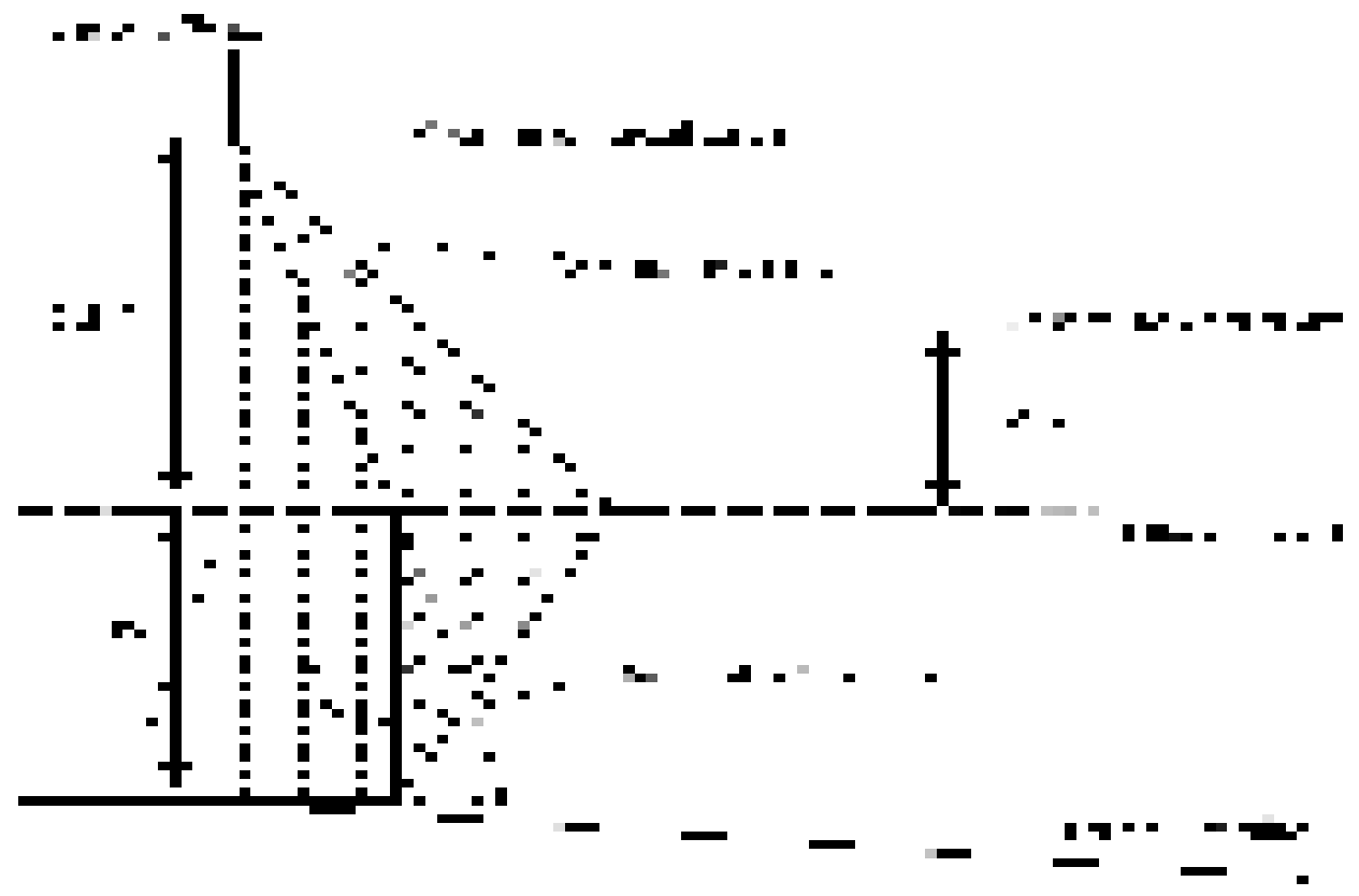
2.6.5 Soil and Hydrostatic Pressure
For structures or portions thereof, lying below ground level, loads due to soil and hydrostatic pressure shall be determined in accordance with the provisions of this Section and applied in addition to all other applicable loads.2.6.5.1 Pressure on basement wall:
In the design of basement walls and similar vertical or nearly vertical structures below grade, provision shall be made for the lateral pressure of adjacent soil. Allowance shall be made for possible surcharge due to fixed or moving loads. When a portion or the whole of the adjacent soil is below the surrounding water table, computations shall be based on the submerged unit weight of soil, plus full hydrostatic pressure.2.6.5.2 Uplift on floors:
In the design of basement floors and similar horizontal or nearly horizontal construction below grade, the upward pressure of water, if any, shall be taken as the full hydrostatic pressure applied over the entire area. The hydrostatic head shall be measured from the underside of the construction.2.6.6 Loads due to Explosions
Loads on buildings or portions thereof, shall be assessed in accordance with the provisions of this Section.2.6.6.1 Explosion effects in closed rooms
- (a) Determination of Loads and Response: Internal overpressure developed from an internal explosion such as that due to leaks in gas pipes, evaporation of volatile liquids, internal dust explosion etc., in rooms of sizes comparable to residential rooms and with ventilation areas consisting of window glass breaking at a pressure of 4 kN/m2 (3-4 mm machine made glass) may be calculated from the following method :
- (i) The overpressure, X; provided in Figure 6.2.33(a) shall be assumed to depend on a factor ;/=, where, ; is the total window area in m2 and = is the volume in m3 of the room considered,
- (ii) The internal pressure shall be assumed to act simultaneously upon all walls and floors in one closed room, and
- (iii) The action X; obtained from Figure 6.2.33(a) may be taken as static action.
- (b) Limitations : Procedure for determining explosion loads given in (a) above shall have the following limitations:
- (i) Values of qo given in Figure 6.2.33(a) are based on tests with gas explosions in room corresponding to ordinary residential flats, and may be applied to considerably different conditions with caution after appropriate adjustment of the values based on more accurate information.
- (ii) Figures 6.2.33(a) and 6.2.33(b) shall be taken as guides only, and probability of occurrence of an explosion shall be checked in each case using appropriate values.
2.6.6.2 Minimum design pressure
Walls, floors and roofs and their supporting members separating a use from an explosion exposure, shall be designed to sustain the anticipated maximum load effects resulting from such use including any dynamic effects, but for a minimum internal pressure or suction of 5 kN/m2 , in addition to all other loads specified in this Chapter.2.6.6.3 Design pressure on relief vents
When pressure-relief vents are used, such vents shall be designed to relieve at a maximum internal pressure of 1.0 kN/m2 .2.6.6.4 Loads due to other explosions
Loads arising from other types of explosions, such as those from external gas cloud explosions, external explosions due to high explosives (TNT) etc. shall be determined, for specific cases, by rational analyses based on information from reliable references or specialist advice shall be sought.2.6.7 Vertical Forces on Air Raid Shelters
For the design of air raid shelters located in a building e.g. in the basement below ground level, the characteristic vertical load shall be determined in accordance with provisions of Sec 2.6.7.1 below.2.6.7.1 Characteristic vertical loads
Buildings in which the individual floors are acted upon by a total distributed live load of up to 5.0 kN/m2 , vertical forces on air raid shelters generally located below ground level, such as a basement, shall be considered to have the characteristic values provided in Table 6.2.27. In the case of buildings having floors that are acted upon by a live load larger than 5.0 kN/m2 , above values shall be increased by the difference between the average live loads on all storeys above the one used as the shelter and 5.0 kN/m2 . Table 6.2.28: Characteristic Vertical Loads for an Air Raid Shelter in a Building
(2) Buildings of particularly stable construction shall mean buildings having bearing structural elements made from reinforced in-situ concrete.
2.6.8 Loads on Helicopter Landing Areas
In addition to all other applicable loads provided in this Chapter, including the dead load, the minimum live load on helicopter landing or touch down areas shall be one of the loads L 1 , L 2 or L 3 as given below producing the most unfavourable effect: Where,- I1 = Actual weight of the helicopter in kN,
- [ = A distributed load of 5.0 kN/m2 ,
- m = 0.75 for helicopters equipped with hydraulic - type shock absorbers, and
- = 1.5 for helicopters with rigid or skid-type landing gear.
2.6.9 Erection and Construction Loads
All loads required to be sustained by a structure or any portion thereof due to placing or storage of construction materials and erection equipment including those due to operation of such equipment shall be considered as erection loads. Provisions shall be made in design to account for all stresses due to such loads.2.7 Combinations of Loads
2.7.1 General
Buildings, foundations and structural members shall be investigated for adequate strength to resist the most unfavorable effect resulting from the various combinations of loads provided in this Section. The combination of loads may be selected using the provisions of either Sec 2.7.2 or Sec 2.7.3 whichever is applicable. However, once Sec 2.7.2 or Sec 2.7.3 is selected for a particular construction material, it must be used exclusively for proportioning elements of that material throughout the structure. In addition to the load combinations given in Sections 2.7.2 and 2.7.3 any other specific load combination provided elsewhere in this Code shall also be investigated to determine the most unfavourable effect. The most unfavourable effect of loads may also occur when one or more of the contributing loads are absent, or act in the reverse direction. Loads such as F , H or S shall be considered in design when their effects are significant. Floor live loads shall not be considered where their inclusion results in lower stresses in the member under consideration. The most unfavourable effects from both wind and earthquake loads shall be considered where appropriate, but they need not be assumed to act simultaneously.2.7.2 Combinations of Load effects for Allowable Stress/Strength Design Method
2.7.2.1 Basic combinations
Provisions of this Section shall apply to all construction materials permitting their use in proportioning structural members by allowable stress/strength design method. When this method is used in designing structural members, all loads listed herein shall be considered to act in the following combinations. The combination that produces the most unfavorable effect shall be used in design.- D + F
- D + H + F + L + T
- D + H + F + (Lr or R)
- D + H + F + 0.75 (L + T ) + (Lr or R)
- D + H + F + (W or 0.7 E)
- D + H + F + 0.75 (W or 0.7 E) + 0.75 L + 0.75 (Lr or R)
- 0.6 D + W + H
- 0.6 D + 0.7 E + H
- In Coastal Zones vulnerable to tidal surges, 1.5 Fa shall be added to other loads in combinations (5), (6); E shall be set equal to zero in (5) and (6).
- In non-coastal Zones, 0.75 Fa shall be added to combinations (5), (6) and (7); E shall be set equal to zero in (5) and (6).
2.7.2.2 Stress increase
Unless permitted elsewhere in this Code, increases in allowable stress shall not be used with the loads or load combinations given above in Sec 2.7.2.1.2.7.3 Combinations of Load effects for Strength Design Method
When strength design method is used, structural members and foundations shall be designed to have strength not less than that required to resist the most unfavorable effect of the combinations of factored loads listed in the following Sections:2.7.3.1 Basic combinations
- 1.4( D + F )
- 1.2( D + F + T ) + 1.6( L + H ) + 0.5( Lr or R )
- 1.2 D + 1.6( Lr or R ) + ( L or 0.8 W )
- 1.2 D + 1.6 W + L + 0.5( Lr or R )
- 1.2 D + 1.0 E + 1.0 L
- 0.9 D + 1.6 W + 1.6 H
- 0.9 D + 1.0 E + 1.6 H
- The load factor on live load L in combinations (3), (4), and (5) is permitted to be reduced to 0.5 for all occupancies in which minimum specified uniformly distributed live load is less than or equal to 5.0 kN/m2 , with the exception of garages or areas occupied as places of public assembly.
- The load factor on H shall be set equal to zero in combinations (6) and (7) if the structural action due to H counteracts that due to W or E . Where lateral earth pressure provides resistance to structural actions from other forces, it shall not be included in H but shall be included in the design resistance.
- For structures designed in accordance with the provisions of Chapter 6, Part 6 of this Code (reinforced concrete structures), where wind load W has not been reduced by a directionality factor, it shall be permitted to use 1.3 W in place of 1.6 W in (4) and (6) above.
- In Coastal Zones vulnerable to tidal surges, 1.6 W shall be replaced by 1.6 W +2.0 Fa in combinations (4) and (6).
- In Non-coastal Zones, 1.6 W shall be replaced by 0.8 W +1.0 Fa in combinations (4) and (6).
2.7.4 Load Combinations for Extraordinary Events
Where required by the applicable Code, standard, or the authority having jurisdiction, strength and stability shall be checked to ensure that structures are capable of withstanding the effects of extraordinary (i.e., low-probability) events, such as fires, explosions, and vehicular impact.2.7.5 Load Combination for Serviceability
Serviceability limit states of buildings and structures shall be checked for the load combinations set forth in this Section as well as mentioned elsewhere in this Code. For serviceability limit states involving visually objectionable deformations, repairable cracking or other damage to interior finishes, and other short term effects, the suggested load combinations for checking vertical deflection due to gravity load is1. D + L
For serviceability limit states involving creep, settlement, or similar long-term or permanent effects, the suggested load combination is:2. D + 0.5 L
The dead load effect, D , used in applying combinations 1 and 2 above may be that portion of dead load that occurs following attachment of nonstructural elements. In applying combination 2 above to account for long term creep effect, the immediate (e.g. elastic) deflection may be multiplied by a creep factor ranging from 1.5 to 2.0. Serviceability against gravity loads (vertical deflections) shall be checked against the limits set forth in Sec 1.2.5 Chapter 1 of this Part as well as mentioned elsewhere in this Code. For serviceability limit state against lateral deflection of buildings and structures due to wind effect, the following combination shall be used:- D + 0.5 L + 0.7 W