
7.1 Introduction
7.1.1 Scope
This Chapter of the Code covers the design, construction and quality control of masonry structures.7.1.2 Definitions
For the purpose of this Chapter, the following definitions shall be applicable.7.1.3 Symbols and Notation
The following units shall be generally implicit in this Chapter for the corresponding quantities:- = Cross-sectional area of anchor bolt
- = Effective area of masonry
- = Gross area of wall
- = Net area of masonry section bounded by wall thickness and length of section in the direction of shear force considered
- = Area of tension (pullout) cone of an embedded anchor bolt projected into the surface of masonry
- = Effective cross-sectional area of reinforcement in a flexural member
- = Area of steel required for shear reinforcement perpendicular to the longitudinal reinforcement
7.2 Materials
7.2.1 General
All materials used in masonry construction shall conform to the requirements specified in Part 5 of this Code. If no requirements are specified for a material, quality shall be based on generally accepted good practice, subject to the approval of the building official.7.2.2 Masonry Units
The following types of masonry units which conform to the standards mentioned in Sec 2.2.4 of Part 5 may be used in masonry construction:- (a) Common building clay bricks
- (b) Burnt clay hollow bricks
- (c) Burnt clay facing bricks
- (d) Hollow concrete blocks
7.2.3 Mortar and Grout
Mortar and grout for masonry construction shall conform to the requirements specified in Part 5 of this Code. Mix proportions and compressive strength of some commonly used mortars are given in Table 6.7.1.7.3 Allowable Stresses
7.3.1 General
Stresses in masonry shall not exceed the values given in this Section. All allowable stresses for working stress design may be increased one third when considering wind or earthquake forces either acting alone or combined with vertical loads. No increase shall be allowed for vertical loads acting alone. r17.3.2 Specified Compressive Strength of Masonry, r1
The allowable stresses for masonry construction shall be based on the value of fras determined by Sec 7.3.3 below. Table 6.7.1: Mix Proportion and Strength of Commonly used Mortars- 1 Sand and cement shall be measured in loose volume and sand shall be well graded with a minimum F.M. of 1.20
- 2 Lime to a maximum of one fourth (1/4) part by volume of cement may be used to increase workability.
7.3.3 Compliance with r1
Compliance with the requirements for the specified compressive strength of masonry, ‘_m$ shall be in accordance with the following:7.3.3.1
Masonry Prism Testing: The compressive strength of masonry based on tests at 28 days in accordance with “Standard Test Method for Compressive Strength of Masonry Prisms”, (ASTM E447) for each set of prisms shall equal or exceed ‘_m$ . Verification by masonry prism testing shall meet the following :- (a) Testing Prior to Construction: A set of five masonry prisms shall be built and tested in accordance with ASTM E447 prior to the start of construction. Materials used for prisms shall be same as used in the project. Prisms shall be constructed under the observation of the engineer or an approved agency and tested by an approved agency.
- (b) Testing During Construction: When full allowable stresses are used in design, a set of three prisms shall be built and tested during construction in accordance with (ASTM E447) for each 500 square meters of wall area, but not less than one set of three masonry prisms for any project. No testing during construction shall be required when 50% of the allowable stresses are used in design.
7.3.4 Quality Control
Quality control shall include, but not be limited to assure that:- (a) Masonry units, reinforcement, cement, lime, aggregate and all other materials meet the requirements of the applicable standard of quality and that they are properly stored and prepared for use.
- (b) Mortar and grout are properly mixed using specified proportions of ingredients. The method of measuring materials for mortar and grout shall be such that proportions of materials are controlled.
- (c) Construction details, procedures and workmanship are in accordance with the plans and specification.
- (d) Placement, splices and bar diameters are in accordance with the provisions of this Chapter and the plans and specifications.
7.3.5 Allowable Stresses in Masonry
When the quality control provisions specified in Sec 7.3.4 above do not include requirements for special inspection, the allowable design stresses in this Section shall be reduced by 50 percent.- (a) Axial Compressive Stress
- (i) Unreinforced masonry walls, columns and reinforced masonry wall
- (c) Tensile Stress of Walls in Flexure
- (d) Reinforcing Bond Stress, u
- (e) Shear Stress for Flexural Members,
- (i) When no shear reinforcement is used
- (i) When shear reinforcement is not provided to resist entire shear force, N/mm (6.7.4)
- (ii) When shear reinforcement is designed to take entire shear force, N/mm (6.7.5)
- (f) Shear Stress for Shear Walls,
- (i) Unreinforced masonry
- M1 or M2 Mortar: 0.20 N/mm2 M3 Mortar: 0.12 N/mm2
- (ii) The allowable shear stress for reinforced masonry shear walls shall be according to Table 6.7.4.
7.3.6 Allowable Stresses in Reinforcement
- (a) Tensile Stress
- (i) Deformed bars,
- (ii) Ties, anchors and plain bars,
- (b) Compressive Stress
- (i) Deformed bars in columns and shear walls,
- (ii) Deformed bars in flexural members
7.3.7 Combined Compressive Stress
Members subject to combined axial and flexural stresses shall be designed in accordance with accepted principles of mechanics or in accordance with the following formula:7.3.8 Modulus of Elasticity
The modulus of elasticity of masonry shall be determined by the secant method. The slope of the line connecting the points and on the stressstrain curve shall be taken as the modulus of elasticity of masonry. If required, actual values shall be established by tests. These values are not to be reduced by 50 per cent as specified in Sec 7.3.5(a).- (a) Modulus of Elasticity for Masonry
- (b) Modulus of Elasticity for Steel
- (c) Shear Modulus of Masonry
7.3.9 Shear and Tension on Embedded Anchor Bolts
7.3.9.1
Allowable loads and placement requirements for anchor bolts shall be in accordance with the following:- (a) Bent bar anchor bolts shall have a hook with a 90o bend with an inside diameter of plus an extension of at the free end.
- (b) Headed anchor bolts shall have a standard bolt head.
- (c) Plate anchor bolts shall have a plate welded to the shank to provide anchorage equivalent to headed anchor bolts.
7.3.9.2
The effective embedment length, for bent bar anchors shall be the length of embedment measured perpendicular from the surface of the masonry to the bearing surface of the bent end minus one anchor bolt diameter. For plate or headed anchor bolts shall be the length of embedment measured perpendicular from the surface of the masonry to the bearing surface of the plate or head of the anchorage. All bolts shall be grouted in place with at least 25 mm of grout between the bolt and the masonry except that 6 mm diameter bolts may be placed in bed joints which are at least twice as thick as the diameter of the bolt.7.3.9.3 Allowable shear force
Allowable loads in shear shall be according to Table 6.7.5 or lesser of the value obtained from the following formulae: When the distance is less than , the value of in Eq. 6.7.15 shall be reduced to zero at a distance equal to 40 mm. Where adjacent anchors are spaced closer than , the allowable shear of the adjacent anchors determined by Eq. 6.7.15 shall be reduced by interpolation to 0.75 times the allowable shear value at a centre to centre spacing of .7.3.9.4 Allowable tension
Allowable tension shall be the lesser value selected from Table 6.7.6 and Table 6.7.7 or shall be determined from lesser of the values obtained from the following formulae: The area shall be the lesser of the area obtained from Equations 6.7.17 and 6.7.18 and where the projected areas of adjacent anchor bolts overlap, of each anchor bolt shall be reduced by 50 percent of the overlapping area. Table 6.7.5: Allowable Shear, Bv for Embedded Anchor Bolts for Masonry, kN*- Values are for bolts of at least ASTM A307 quality. Bolts shall be those specified in Sec 4.3.9.1.
- 1 The allowable tension values are based on compressive strength of masonry assemblages. Where yield strength of anchor bolt steel governs, the allowable tension is given in Table 6.7.7.
- 2 Values are for bolts of at least ASTM A307 quality. Bolts shall be those specified in Sec 7.3.9.1.
7.3.9.5 Combined shear and tension
Anchor bolts subjected to combined shear and tension shall be designed in accordance with the formula given below:7.3.9.6 Minimum edge distance,
The minimum value of measured from the edge of the masonry parallel to the anchor bolt to the surface of the anchor bolt shall be 40 mm.7.3.9.7 Minimum embedment depth,
The minimum embedment depth shall be but not less than 50 mm.7.3.9.8 Minimum spacing between bolts
The minimum centre to centre spacing between anchors shall be .7.3.10 Load Test
For load test, the member shall be subject to a superimposed load equal to twice the design live load plus one-half of the dead load. This load shall be maintained for a period of 24 hours. If, during the test or upon removal of the load, the member shows evidence of failure, such changes or modifications as are necessary to make the structure adequate for the rated capacity shall be made; or where possible, a lower rating shall be established. A flexural member shall be considered to have passed the test if the maximum deflection at the end of the 24 hour period neither exceeds nor and the beam and slabs show a recovery of at least 75 percent of the observed deflection within 24 hours after removal of the load.7.3.11 Reuse of Masonry Units
Masonry units may be reused when clean, unbroken and conforms to the requirements of Part 5. All structural properties of masonry of reclaimed units, especially adhesion bond, shall be determined by approved test. The allowable working stress shall not exceed 50 percent of that permitted for new masonry units of the same properties.7.4 Basic Design Requirements
7.4.1 General
Masonry structures shall be designed according to the provisions of this Section. The required design strengths of masonry materials and any special requirements shall be specified in the plan submitted for approval.7.4.2 Design Considerations
7.4.2.1
Masonry structures shall be designed based on working stress and linear stress-strain distribution. Requirements for working stress design of unreinforced and reinforced masonry structures are provided in Sections 4.5 and 4.6 respectively. In lieu of the working stress design method, slender walls and shear walls may be designed by the strength design method specified in Sec 7.7. The structure shall be proportioned such that eccentricity of loading on the members is as small as possible. Eccentric loading shall preferably be avoided by providing:- (a) adequate bearing of floor/roof on the walls
- (b) adequate stiffness in slabs, and
- (c) fixity at the supports.
7.4.2.2 Effective height
- (a) Wall: The effective height of a wall shall be taken as the clear height between the lateral supports at top and bottom in a direction normal to the axis considered. For members not supported at the top normal to the axis considered, the effective height is twice the height of the member above the support. Effective height less than the clear height may be used if justified.
- (b) Column: Effective height of the column shall be taken as actual height for the direction it is laterally supported and twice the actual height for the direction it is not laterally supported at the top normal to the axis considered.
- (c) Opening in Wall: When openings occur in a wall such that masonry between the openings is by definition a column, effective height of masonry between the openings shall be obtained as follows:
- (i) When wall has full restraint at the top, effective height for the direction perpendicular to the plane of wall equals 0.75… plus 0.25…r , where … is the distance between supports and …r is the height of the taller opening; and effective height for the direction parallel to the wall equals ….
- (ii) When wall has partial restraint at the top and bottom, effective height for the direction perpendicular to the plane of wall equals … when height of neither opening exceeds 0.5… and it is equal to 2… when height of any opening exceeds0.5…; and effective height for the direction parallel to the plane of the wall equals 2….
7.4.2.3 Effective length
Effective length of a wall for different support conditions shall be as given in Table 6.7.8.7.4.2.4 Effective thickness
The effective thickness of walls and columns for use in the calculation of slenderness ratio, shall be defined as follows:- (a) Solid Walls: The effective thickness of solid walls, faced walls or grouted walls shall be the specified thickness of the wall.
- (b) Solid Walls with Raked Mortar Joints: The effective thickness of solid walls with raked mortar joints shall be the minimum thickness measured at the joint.
- (c) Cavity Walls: When both limbs of a cavity wall are axially loaded, each limb shall be considered independently and the effective thickness of each limb shall be determined as in (a) or (b) above. If one of the limbs is axially loaded, the effective thickness of the cavity wall shall be taken as the square root of the sum of the squares of the effective thicknesses of the limbs.
- (d) Walls Stiffened by Pilasters: When solid or cavity walls are stiffened by pilasters at intervals, the effective thickness to be used for the calculation of ratio shall be determined as follows:
- (i) Solid Walls: For stiffened solid walls the effective thickness shall be the specified thickness multiplied by the stiffening coefficient, k, values of which are given below:
- Linear interpolation is permitted for obtaining intermediate values of k
- Where, = centre to centre spacing of pilasters
- = thickness of pilaster including the wall
- = specified thickness of main wall
- = width of pilaster in the direction of wall
- (ii) Cavity Walls: When one or both limbs of a cavity wall are adequately bonded into pilasters at intervals, the effective thickness of each limb shall be determined separately as in (a), (b) or d above and the effective thickness of the stiffened cavity wall shall be determined in accordance with (c) above.
- (e) Columns: The effective thickness for rectangular columns in the direction considered is the actual thickness provided in that direction. The effective thickness for nonrectangular columns is the thickness of a square column with the same moment of inertia about its axis as that about the axis considered in the actual column.
7.4.2.5 Slenderness ratio
- (a) Walls: For a wall, slenderness ratio shall be the ratio of effective height to effective thickness or effective length to effective thickness whichever less is. In case of a load bearing wall, slenderness ratio shall not exceed 20.
- (b) Column: For a column, slenderness ratio shall be taken to be the greater of the ratio of effective heights to the respective effective thickness in the two principal directions. Slenderness ratio for a load bearing column shall not exceed 12.
7.4.2.6 Effective area
The effective cross-sectional area shall be based on the minimum bedded area of the hollow units, or the gross area of solid units plus any grouted area. If hollow units are used perpendicular to the direction of stress, the effective area shall be lesser of the minimum bedded area or the minimum cross-sectional area. If bed joints are raked, the effective area shall be correspondingly reduced. Effective areas for cavity walls shall be that of the loaded wythes.7.4.2.7 Flexural resistance of cavity walls
For computing the flexural resistance, lateral loads perpendicular to the plane of the wall shall be distributed to the wythes according to their respective flexural rigidities.7.4.2.8 Effective width of intersecting walls
Where a shear wall is anchored to an intersecting wall or walls, the width of the overhanging flange formed by the intersected walls on either side of the shear wall shall not exceed 6 times the thickness of the intersected wall. Limits of the effective flange may be waived if justified. Only the effective area of the wall parallel to the shear forces may be assumed to carry horizontal shear.7.4.3 Supports
7.4.3.1 Vertical support
Structural members providing vertical support of masonry shall provide a bearing surface on which the initial bed joint shall not be less than 6 mm or more than 25 mm and shall be of noncombustible materials, except where masonry is a nonstructural decorative feature or wearing surface.7.4.3.2 Vertical deflection
Elements supporting masonry shall be designed so that their vertical deflection does not exceed 1/600 of the clear span under total loads. Lintels shall be supported on each end such that allowable stresses in the supporting masonry are not exceeded. The minimum bearing length shall be 100 mm.7.4.3.3 Lateral support
- (a) Lateral support of masonry may be provided by cross walls, columns, piers, counter forts or buttresses when spanning horizontally or by floors, beams or roofs when spanning vertically.
- (b) Lateral supports for a masonry element such as load bearing wall or column shall be provided to
- (i) limit the slenderness of a masonry element so as to prevent or reduce possibility of buckling of the member due to vertical loads; and
- (ii) resist the horizontal components of forces so as to ensure stability of a structure against overturning.
- (c) From consideration of slenderness (i.e. requirement b(i) above), masonry elements may be considered to be laterally supported if
- (i) in case of a wall, where slenderness ratio is based on effective height, floor/roof slab (or beams and slab) irrespective of the direction of span, bears on the supported wall as well as cross walls, to the extent of at least 100 mm;
- (ii) in case of a wall, when slenderness ratio is based on its effective length, a cross wall/pier/buttress of thickness equal to or more than half the thickness of the supported wall or 125 mm, whichever is more and average length equal to or more than one-fifth of the height of the wall, is built at right angle to the wall and properly bonded;
- (iii) in case of a column, an RC or timber beam/RS joist/roof truss, is supported on the column. In this case, the column will not be considered to be laterally supported in the direction at right angle to it; and
- (iv) in case of a column, an RC beam forming a part of beam and slab construction, is supported on the column, and the slab adequately bears on stiffening walls. This construction will provide lateral support to the column, in the direction of both horizontal axes.
7.4.4 Stability
A wall or column subject to vertical and lateral loads may be considered to provide adequate lateral support from consideration of stability, if the construction providing the support is capable of resisting the following forces:- (a) Simple static reactions at the point of lateral support to all the lateral loads; plus
- (b) A lateral load equal to 2.5% of the total vertical load that the wall or column is designated to carry at the point of lateral support.
7.4.4.1
In case of load bearing buildings up to five storeys, stability requirements may be considered to have been satisfied if the following conditions are met.- (a) Height to width ratio of building does not exceed 2.
- (b) Cross walls acting as stiffening walls continuous from outer wall to outer wall or outer wall to a load bearing inner wall, and of thickness and spacing as given in Table 6.7.9 are provided.
- (c) Floors and roof either bear on cross walls or are properly anchored to those walls such that all lateral loads are safely transmitted to those walls and through them to the foundation.
- (d) Cross walls are built jointly with the bearing walls and jointly mortared, or interconnected by toothing.
- Storey height and maximum spacing as given are centre to centre dimensions.
7.4.4.2
In case of walls exceeding 8 m in length, safety and adequacy of lateral supports shall always be checked by structural analysis.7.4.4.3
A trussed roofing may not provide lateral support unless special measures are adopted to brace and anchor the roofing. However, in case of residential and similar buildings of conventional design with trussed roofing having cross walls, it may be assumed that stability requirements are met by the cross walls and structural analysis for stability may be dispensed with.7.4.4.4
In case of walls exceeding 8 m in length, safety and adequacy of lateral supports shall always be checked by structural analysis.7.4.4.5
A trussed roofing may not provide lateral support unless special measures are adopted to brace and anchor the roofing. However, in case of residential and similar buildings of conventional design with trussed roofing having cross walls, it may be assumed that stability requirements are met by the cross walls and structural analysis for stability may be dispensed with.7.4.4.6
In case of external walls of basement and plinth, stability requirements of Sec 7.4.4 may be considered to be satisfied if :- (a) Bricks used in basement and plinth have a minimum crushing strength of 5 N/mm² and mortar used in masonry is of Type M3 or better,
- (b) Clear height of ceiling in basement does not exceed 2.6 m,
- (c) In the zone of action of soil pressure on basement walls, traffic load excluding any surcharge due to adjoining buildings does not exceed 5 kN/m2 ,
- (d) Minimum thickness of basement walls is in accordance with Table 6.7.10.
7.4.4.7 Free standing wall
Free standing walls, subject to wind pressure or seismic forces shall be designed on the basis of permissible tensile stress in masonry or stability consideration. However in Seismic Zones 1 and 2, free standing walls may be proportioned without making any design calculations with the help of Table 6.7.11 provided the mortar used is of type not leaner than M3. For parapet wall see Sec 7.4.9.4.7.4.5 Structural Continuity
Intersecting structural elements intended to act as a unit shall be anchored together to resist the design forces. Walls shall be anchored together to all floors, roofs or other elements which provide lateral support for the wall. Where floors or roofs are designed to transmit horizontal forces to walls, the anchorages to the walls shall be designed to resist the horizontal forces. Table 6.7.11: Height to Thickness Ratio of Free Standing Wall7.4.5.1 Multi-wythe Walls
All wythes shall be bonded by grout or tied together by corrosion resistant wall ties or joint reinforcement as follows:- (a) Wall Ties in Cavity Wall Construction: Wall ties shall be of sufficient length to engage all wythes. The portion of the wall ties within the wythe shall be completely embedded in mortar or grout. The ends of the wall ties shall be bent to 90 degree angles with an extension not less than 50 mm long. Wall ties not completely embedded in mortar or grout between wythes shall be a single piece with each end engaged in each wythe.
- (b) Wall Ties for Grouted Multi-wythe Construction: The two wythes shall be bonded together with at least 6 mm diameter steel wall ties for each 0.20 m2 of area. Wall ties of different size and spacing may be used if they provide equivalent strength between wythes.
- (c) Joint Reinforcement: Prefabricated joint reinforcement for masonry walls shall have a minimum of one cross wire of at least 3 mm diameter steel for each 0.2 m2 of wall area. The vertical spacing of the joint reinforcement shall not exceed 400 mm. The longitudinal wires shall be thoroughly embedded in the bed joint mortar. The joint reinforcement shall engage all wythes.
7.4.6 Joint Reinforcement and Protection of Ties
The minimum mortar cover between ties or joint reinforcement and any exposed face shall be 15 mm. The thickness of grout or mortar between masonry units and joint reinforcement shall not be less than 6 mm, except that smaller diameter reinforcement or bolts may be placed in bed joints which are at least twice as thick as the diameter of the reinforcement.7.4.7 Pipes and Conduits
Pipe or conduit shall not be embedded in any masonry so as to reduce the capacity to less than that necessary for required stability or required fire protection, except the following:- (a) Rigid electrical conduit may be embedded in structural masonry when their location has been detailed on the approved plan.
- (b) Any pipe or conduit may pass vertically or horizontally through any masonry by means of a sleeve at least large enough to pass any hub or coupling on the pipeline. Such sleeves shall not be placed closer than three diameters, centre to centre, nor shall they unduly impair the strength of construction.
- (c) Placement of pipes or conduits in unfilled cores of hollow unit masonry shall not be considered as embedment.
7.4.8 Loads and Load Combination
7.4.8.1 Design loads
All design loads and other forces to be taken for the design of masonry structures shall conform to Chapter 2, Loads.7.4.8.2 Load dispersion
The angle of dispersion of vertical load on walls shall be taken as not more than 30o from the vertical.7.4.8.3 Distribution of concentrated vertical loads in walls
The length of wall, laid up in running bond, which may be considered capable of working at the maximum allowable compressive stresses to resist vertical concentrated loads, shall not exceed the centre to centre distance between such loads, nor the width of bearing area plus four times the wall thickness. Concentrated vertical loads shall not be assumed distributed across continuous vertical mortar or control joints unless elements designed to distribute the concentrated vertical loads are employed.7.4.8.4 Loads on non-bearing wall
Masonry walls used as interior partition or as exterior surfaces of building which do not carry vertical loads imposed by other elements of the building shall be designed to carry their own weight plus any superimposed finish and lateral forces. Bonding or anchorage of nonbearing walls shall be adequate to support the walls and to transfer lateral forces to the supporting structures.7.4.8.5 Load combinations
Load combination for design of masonry structures shall conform to requirements of Sec 2.7 Chapter 2 Part 6.7.4.9 Minimum Design Dimensions
7.4.9.1 Minimum thickness of load bearing walls
The nominal thickness of masonry bearing walls in building shall not be less than 250 mm. Exception: Stiffened solid masonry bearing walls in one-storey buildings may have a minimum effective thickness of 165 mm when not over 3 m in height, provided that when gable construction is used an additional 1.5 m height may be permitted at the peak of the gable.7.4.9.2 Variation in thickness
When a change in thickness due to minimum thickness requirements occurs between floor levels, the greater thickness shall be carried up to the higher floor level.7.4.9.3 Decrease in thickness
When walls of masonry of hollow units or masonry bonded hollow walls are decreased in thickness, a course or courses of solid masonry shall be constructed between the walls below and the thinner wall above, or special units or construction shall be used to transmit the loads from wythes to the walls below.7.4.9.4 Parapet wall
Parapet walls shall be at least 200 mm thick and height shall not exceed 4 times the thickness. The parapet wall shall not be thinner than the wall below.7.5 Design of Unreinforced Masonry
7.5.1 General
The requirements of this Section are applicable to unreinforced masonry in addition to the requirements of Sec 7.4.7.5.2 Design of Members Subjected to Axial Compression
The stresses due to compressive forces applied at the centroid of any load bearing wall, column and pilaster may be computed by Eq. 6.7.22 below assuming uniform distribution over the effective area.7.5.3 Design of Members Subjected to Combined Bending and Axial Compression
- (a) Compressive stresses due to combined bending and axial load shall satisfy the requirements of Sec 7.3.5.
- (b) Resultant tensile stress due to combined bending and axial load shall not exceed the allowable flexural tensile stress, as specified in Sec 7.3.
7.5.4 Design of Members Subjected to Flexure
Stresses due to flexure calculated by Eq. 6.7.23 below shall not exceed the values given in Sec 7.3.5.7.5.5 Design of Members Subjected to Shear
Shear calculations in flexural members and shear walls shall be based on Eq. 6.7.24 below.7.5.6 Design of Arches
Geometrical form and the cross-sectional dimensions of masonry arch shall be selected such that the line of thrust at any section of the arch is kept within the middle third of the section of the arch rib. The elastic theory of arches shall be permitted for the analysis of unreinforced masonry arches. All supports of arches shall be capable of developing the required horizontal thrust without suffering unacceptable displacements. Every arch must be designed to resist the stresses due to the following loads:- (a) Gravity loads :
- (i) Dead loads shall be placed in conformity with their actual distribution.
- (ii) Live loads shall be positioned to cover entire span or part of the span as necessary to produce the maximum stresses at the crown, springing and all other sections of the arch rib.
- (b) Loads due to temperature change.
- (c) Shrinkage load due to setting and hardening.
- (d) Shortening of arch rib under thrust caused by loads.
7.5.7 Footings and Corbels
The slope of footing and corbelling (measured from the horizontal to the face of the corbelled surface) shall not be less than 60 degrees. The maximum horizontal projection of corbelling from the plane of the wall shall be such that stress at any section does not exceed the allowable value.7.6 Design of Reinforced Masonry
7.6.1 General
The requirements of this Section are in addition to those specified in Sec 7.4 and are applicable to reinforced masonry. Plain bars larger than 6 mm in diameter shall not be used.7.6.1.1 Assumptions
The following assumptions shall be applicable for this Section.- (a) Masonry carries no tensile stress.
- (b) Reinforcement is completely surrounded by and bonded to masonry material so that they work together as a homogeneous material within the range of working stresses.
7.6.2 Design of Members Subjected to Axial Compression
Stresses due to compressive forces applied at the centroid of load bearing wall, column and pilaster may be computed assuming uniform distribution over the effective area. Stress shall be calculated from Eq. 6.7.25 below:7.6.3 Design of Members Subjected to Combined Bending and Axial Compression
Stress due to combined bending and axial loads shall satisfy the requirements of Sec 7.3.5. Columns and walls subjected to bending with or without axial loads shall meet all applicable requirements for flexural design. The design of walls with an ratio larger than 30 shall be based on forces and moments determined from analysis of structure. Such analysis shall take into account influence of axial loads and variable moment of inertia on member stiffness and fixed end moments, effect of deflections on moments and forces, and the effects of duration of loads.7.6.4 Design of Members Subjected to Shear Force
Shearing stresses in flexural members and shear walls shall be computed by When the computed shear stress exceeds the allowable value, web reinforcement shall be provided and designed to carry the total shear force. Both vertical and horizontal shear stresses shall be considered. The area required for shear reinforcement placed perpendicular to the longitudinal reinforcement shall be computed by Eq. 6.7.27 below: Spacing of vertical shear reinforcement shall not exceed d/2, nor 600 mm. Inclined shear reinforcement shall have a maximum spacing of , but not greater than 600 mm, where α is the acute angle between inclined bar and the horizontal.7.6.5 Design of Members Subjected to Flexural Stress
7.6.5.1 Rectangular elements
Rectangular flexural elements shall be designed in accordance with the following equations or other methods based on the simplified assumptions.- (a) Compressive stress in the masonry:
7.6.5.2 Nonrectangular sections
Flexural elements of nonrectangular cross-section shall be designed in accordance with the assumptions given in Sec 7.4.2.1 and 7.6.1.1.7.6.5.3 Lateral support
The clear distance between lateral supports of a beam shall not exceed 32 times the least depth of compression area.7.6.5.4 Effective width
In computing flexural stresses in walls where reinforcement occurs, the effective width assumed for running bond masonry shall not exceed 6 times the nominal wall thickness or the centre to centre distance between reinforcement. Where stack bond is used, the effective width shall not exceed 3 times the nominal wall thickness or the centre to centre distance between reinforcement or the length of one unit, unless grouted solid using open-ended joints.7.6.5.5 Bond
In flexural members in which tensile reinforcement is parallel to the compressive face, the bond stress shall be computed by the formula:7.6.6 Reinforcement Requirements and Details
7.6.6.1 Column reinforcement
- (a) Vertical Reinforcement: The area of vertical reinforcement shall not be less than and not more than . At least four 10 mm diameter bars shall be provided.
- (b) Lateral Ties: All longitudinal bars for columns shall be enclosed by lateral ties. Lateral support shall be provided to the longitudinal bars by the corner of a complete tie having an included angle of not more than 135 degrees or by a hook at the end of a tie. The corner bars shall have such support provided by a complete tie enclosing the longitudinal bars. Alternate longitudinal bars shall have such lateral support provided by ties and no bar shall be farther than 150 mm from such a laterally supported bar.
- (c) Anchor Bolt Ties: Additional ties shall be provided around anchor bolts which are set in the top of the column. Such ties shall engage at least four bolts or, alternatively at least four vertical column bars or a combination of bolts and bars totaling four in number. Such ties shall be located within the top 125 mm of the column and shall provide a total of 250 square millimeters or more in cross-sectional area. The upper most ties shall be within 50 mm of the top of the column.
7.6.6.2 Maximum reinforcement size
The maximum size of reinforcing bars shall be 35 mm. Maximum steel area in cell shall be 6 percent of the cell area without splices and 12 percent of cell area with splices.7.6.6.3 Spacing of longitudinal reinforcement
The clear distance between parallel bars, except in columns, shall not be less than the nominal diameter of the bars or 25 mm, except that bars in a splice may be in contact. This clear distance requirement applies to the clear distance between a contact splice and adjacent splices or bars. The minimum clear distance between parallel bars in columns shall be two and one-half times the bar diameter. The clear distance between the surface of a bar and any surface of a masonry unit shall not be less than 6 mm for fine grout and 12 mm for coarse grout. Cross webs of hollow units may be used as support for horizontal reinforcement. All reinforcing bars, except joint reinforcing, shall be completely embedded in mortar or grout and have a minimum cover, including the masonry unit, as specified below:- (a) 20 mm when not exposed to weather
- (b) 40 mm when exposed to weather
- (c) 50 mm when exposed to soil
7.6.6.4 Anchorage of Flexural Reinforcement
- (a) The tension or compression in any bar at any section must be developed on each side of that section by the required development length. The development length of the bar may be achieved by a combination of an embedment length, anchorage or, for tension only, hooks.
- (b) Except at supports, or at the free end of cantilevers, every reinforcing bar shall be extended beyond the point at which it is no longer needed to resist tensile stress for a distance equal to 12 bar diameters or the depth of the flexural member, whichever is greater. No flexural bars shall be terminated in a tensile zone unless one of the following conditions is satisfied:
- (i) The shear is not over one-half of that permitted, including allowance for shear reinforcement, if any.
- (ii) Additional shear reinforcement in excess of that required is provided each way from the cutoff a distance equal to the depth of the beam. The shear reinforcement spacing shall not exceed d/8rb, where rbis the ratio of the area of bars cutoff to the total area of bars at the section.
- (iii) The continuing bars provide double the area required for flexure at that point or double the perimeter required for reinforcing bond.
- (c) At least one third of the total reinforcement provided for negative moment at the support shall be extended beyond the extreme position of the point of inflection a distance sufficient to develop one half the allowable stress in the bar, one sixteenth of the clear span, or the depth d of the member, whichever is greater.
- (d) Tensile reinforcement of negative moment in any span of a continuous restrained or cantilever beam, or in any member of a rigid frame, shall be adequately anchored by reinforcing bond, hooks or mechanical anchors in or through the supporting member.
- (e) At least one third of the required positive moment reinforcement in simple beams or at the freely supported end of continuous beams shall extend along the same face of the beam into the support at least 150 mm. At least one fourth of the required positive moment reinforcement at the continuous end of continuous beams shall extend along the same face of the beam into the support at least 150 mm.
- (f) Compression reinforcement in flexural members shall be anchored by ties or stirrups not less than 6 mm in diameter, spaced not farther apart than 16 bar diameters or 48 tie diameters whichever is smaller. Such ties or stirrups shall be used throughout the distance where compression steel is required.
- (g) In regions of moment where the design tensile stresses in the steel are greater than 80 percent of the allowable steel tensile stress (Fs), the lap length of splices shall be increased not less than 50 percent of the minimum required length. Other equivalent means of stress transfer to accomplish the same 50 percent increase may be used.
7.6.6.5 Anchorage of shear reinforcement
- (a) Single separate bars used as shear reinforcement shall be anchored at each end by one of the following methods:
- (i) Hooking tightly around the longitudinal reinforcement through 180 degrees.
- (ii) Embedment above or below the mid-depth of the beam on the compression side a distance sufficient to develop the stress in the bar for plane or deformed bars.
- (iii) By a standard hook (see Sec 7.6.6.6) considered as developing 50 N/mm² , plus embedment sufficient to develop the remainder of the stress to which the bars are subject. The effective embedded length shall not be assumed to exceed the distance between the mid-depth of the beam and the tangent of the hook.
- (b) The ends of bars forming single U or multiple U stirrups shall be anchored by one of the methods specified above or shall be bent through an angle of at least 90 degrees tightly around a longitudinal reinforcing bar not less in diameter than the stirrup bar, and shall project beyond the bend at least 12 diameters of the stirrup.
- (c) The loops or closed ends of single U or multiple U stirrups shall be anchored by bending around the longitudinal reinforcement through an angle of at least 90 degrees and project beyond the end of the bend at least 12 diameters of the stirrup.
7.6.6.6 Hooks
- (a) The term “standard hook” shall mean one of the following:
- (i) A 180 degree turn plus an extension of at least 4 bar diameters but not less than 65 mm at the free end of the bar.
- (ii) 90 degree turn plus an extension of at least 12 bar diameters at the free end of the bar.
- (iii) For stirrup and tie anchorage only either a 90 degree or a 135 degree turn, plus an extension of at least 6 bar diameters but not less than 65 mm at the free end of the bar.
- (b) The diameter of bend measured on the inside of the bar other than stirrups and ties, shall not be less than that set forth in Table 6.7.12.
- (c) Inside diameter of bend for 12 mm diameter or smaller stirrups and ties shall not be less than 4 bar diameters. Inside diameter of bend for 16 mm diameter or larger stirrups and ties shall not be less than that given in Table 6.7.12.
- (d) Hooks shall not be permitted in the tension portion of any beam, except at the ends of simple or cantilever beams or at the freely supported ends of continuous or restrained beams.
- (e) Hooks shall not be assumed to carry a load which would produce a tensile stress in the bar greater than 50 N/mm² .
- (f) Hooks shall not be considered effective in adding to the compressive resistance of bars.
- (g) Any mechanical device capable of developing the strength of the bar without damage to the masonry may be used in lieu of a hook. Data must be presented to show the adequacy of such devices.
7.6.6.7 Splices
The amount of lap of lapped splices shall be sufficient to transfer the allowable stress of the reinforcement as in Sec 7.6.6.4. In no case shall the length of the lapped splice be less than 30 bar diameters for compression and 40 bar diameters for tension. Welded or mechanical connections shall develop 125 percent of the specified yield strength of the bar in tension, except for connections of compression bars in columns that are not part of the seismic system and are not subject to flexure, where the compressive strength only need be developed. When adjacent splices in grouted masonry are separated by 75 mm or less, the lap length shall be increased by 30 percent or the splice may be staggered at least 24 bar diameters with no increase in lap length.7.7 Strength Design of Slender Walls and Shear Walls
7.7.1 Design of Slender Walls
In lieu of the procedure set forth in Sec 7.6, the procedures prescribed in this Section, which consider the slenderness of walls by representing effects of axial forces and deflection in calculation of moments, may be used when the vertical load stress at the location of maximum moment computed by Eq. 6.7.36 does not exceed . The value of shall not exceed 40 N/mm². Slender masonry walls shall have a minimum nominal thickness of 150 mm.7.7.1.1 Slender wall design procedure
- (a) Maximum Reinforcement: The reinforcement ratio shall not exceed , where is the balanced steel ratio.
- (b) Moment and Deflection Calculation: All moments and deflections of slender walls shall be calculated based on simple support conditions at top and bottom. For other support and fixity conditions, moments and deflections shall be calculated using established principles of mechanics.
7.7.1.2 Strength design
- (a) Loads: Factored loads shall be determined in accordance with Chapter 2, Loads.
- (b) Required Moment: Required moment and axial force shall be determined at the mid-height of the wall and shall be used for design. The factored moment, Mu, at the mid-height of the wall shall be determined by Eq. 6.7.37.
- = horizontal deflection at mid-height under factored load; P - Delta effects shall be included in deflection calculation.
- = eccentricity of
- = axial load at mid-height of wall, including tributary wall weight.
- (c) Design Strength: Design strength in flexure is the nominal moment strength, multiplied by the strength reduction factor, and shall equal or exceed the factored moment, .
- (d) Design Assumptions: The following are the design assumptions for calculation of nominal strength.
- (i) Nominal strength of singly reinforced masonry wall crosssections subject to combined flexure and axial load shall be based on applicable conditions of equilibrium and compatibility of strains.
- (ii) Strain in reinforcement and masonry walls shall be assumed directly proportional to the distance from the neutral axis.
- (iii) Maximum usable strain at extreme masonry compression fibre shall be assumed equal to 0.003.
- (iv) Stress in reinforcement below specified yield strength shall be taken as times steel strain. For strains greater than that corresponding to stress in reinforcement shall be considered independent of strain and equal to.
- (v) Tensile strength of masonry walls shall be neglected in flexural calculations of strength, except for deflection calculation.
- (vi) Relationship between masonry compressive stress and masonry strain may be assumed to be rectangular as defined by the following:
- Masonry stress of 0.85’_m$ shall be assumed uniformly distributed over an equivalent compression zone bounded by edges of the cross-section and a straight line located parallel to the neutral axis at a distance a = 0.85c from the fibre of maximum compressive strain.
- Distance c from fibre of maximum strain to the neutral axis shall be measured in a direction perpendicular to that axis.
7.7.1.3 Deflection calculation
The mid-height deflection, ∆ under service lateral and vertical loads (without load factors) shall be limited to: The mid-height deflection shall be computed by: When, When, The cracking moment strength of the wall shall be determined by: The modulus of rupture, shall be determined form Table 6.7.13. Table 6.7.13: Values of the Modulus of Rupture,7.7.2 Design of Shear Walls
Based on ultimate strength design, the procedures described below may be used as an alternative to the procedure specified in Sec 7.6 for the design of reinforced hollow unit masonry shear walls. Provisions for quality control during construction of the shear wall are specified in Sec 7.3.47.7.2.1 Required strength
The required strength to resist different combinations of loads shall be determined in accordance with Sec 2.7.3.1 Chapter 2 of this Part.7.7.2.2 Design strength
Shear walls shall be proportioned such that the design strength exceeds the required strength. Design strength in terms of axial force, shear force and moment provided by the shear wall shall be computed as the nominal strength multiplied by the strength reduction factor . Strength reduction factor shall be as follows:- (a) For axial load and axial load with flexure = 0.65
- (b) For members with less than 410 N/mm and with symmetrical reinforcement, may be increased linearly to 0.85 as decreases from or to zero.
- (c) For shear = 0.60. The shear strength reduction factor may be increased to 0.80 for any shear wall when its nominal shear strength exceeds the shear corresponding to development of its nominal flexural strength for the factored load combination.
7.7.2.3 Design Assumptions for Nominal Strength
- (a) Nominal strength of shear wall cross-sections shall be based on assumptions specified in Sec 7.7.1.2(d).
- (b) The maximum usable strain , at the extreme masonry compression fibre shall not exceed 0.003.
- (c) shall not be less than 7 N/mm² or greater than 20 N/mm².
7.7.2.4 Axial Strength
The nominal axial strength of shear walls supporting axial loads only shall be calculated by Eq 6.7.44. The shear wall shall be designed for the axial strength Pu, such that7.7.2.5 Shear strength
- (a) The nominal shear strength shall be determined by the provisions as specified in (b) or (c) below. The maximum nominal shear strength values are given in Table 6.7.14.
- (b) The nominal shear strength of shear walls except for shear walls specified in (c) below shall be determined by Eq. 6.7.46.
- (c) For a shear wall whose nominal shear strength exceeds the shear corresponding to development of its nominal flexural strength, two shear regions exist.
- (i) For all cross-sections within the region defined by the base of the shear wall and a plane at a distance above the base of the shear wall, the nominal shear strength shall be determined by Eq. 6.7.49
- (ii) For the other region, the nominal shear strength of the shear wall shall be determined by Eq. 6.7.46.
7.7.2.6 Reinforcement
Reinforcement shall be in accordance with the following:- (a) Minimum reinforcement shall be provided in accordance with Sec 7.8.5.1 for all seismic areas using this method of analysis.
- (b) When the shear wall failure mode is in flexure, the nominal flexural strength of the shear wall shall be at least 1.8 times the cracking moment strength of a fully grouted wall or 3.0 times the cracking moment strength of a partially grouted wall as obtained from Eq. 6.7.42.
- (c) All continuous reinforcement shall be anchored or spliced in accordance with Sec 7.6.6.4 with .
- (d) Vertical reinforcement shall not be less than 50 percent of the horizontal reinforcement.
- (e) Spacing of horizontal reinforcement within the region defined in Sec 7.7.2.5(c) shall not exceed three times the nominal wall thickness or 600 mm, whichever is smaller.
7.7.2.7 Boundary member
Boundary members shall be as follows:- (a) The need for boundary members at boundaries of shear wall shall be determined using the provisions set forth in (b) or (c) below.
- (b) Boundary members shall be provided when the failure mode is flexure and the maximum extreme fibre stress exceeds . The boundary members may be discontinued where the calculated compressive stresses are less than . Stresses may be calculated for the factored forces using a linearly elastic model and gross section properties.
- (c) When the failure mode is flexure, boundary member shall be provided to confine all vertical reinforcement whose corresponding masonry compressive stress exceeds . The minimum length of the boundary member shall be 3 times the thickness of the wall.
- (d) Boundary members shall be confined with minimum of 10 mm diameter bars at a maximum of 200 mm spacing or equivalent within the grouted core and within the region defined by the base of the shear wall and a plane at a distance above the base of the shear wall.
7.8 Earthquake Resistant Design
7.8.1 General
All masonry structures constructed in the Seismic Zones 2, 3 and 4 shown in Figure 6.2.13 shall be designed in accordance with the provisions of this Section.7.8.2 Loads
Seismic forces on masonry structures shall be determined in accordance with the provisions of Sec 2.5 Chapter 2 of this Part.7.8.3 Materials
- (a) Well burnt clay bricks and concrete hollow blocks having a crushing strength not less than 12 N/mm² shall be used.
- (b) Mortar not leaner than p½ shall be used for masonry constructions.
7.8.4 Provisions for Seismic Zone 2 and 3
7.8.4.1 Wall Reinforcement
Vertical reinforcement of at least 12 mm diameter shall be provided continuously from support to support at each corner, at each side of each opening, at the ends of walls and at a maximum spacing of 1.2 m horizontally throughout the wall. Horizontal reinforcement not less than 12 mm diameter shall be provided:- (a) at the bottom and top of wall openings and shall extend at least 40 bar diameters, with a minimum of 600 mm, past the opening,
- (b) continuously at structurally connected roof and floor levels and at the top of walls,
- (c) at the bottom of the wall or in the top of the foundations when dowelled to the wall,
- (d) at maximum spacing of 3.0 m unless uniformly distributed joint reinforcement is provided. Reinforcement at the top and bottom of openings when continuous in the wall may be used in determining the maximum spacing specified in item (a) above.
7.8.4.2 Stack bond
Where stack bond is used, the minimum horizontal reinforcement ratio shall be . This ratio shall be satisfied by uniformly distributed joint reinforcement or by horizontal reinforcement spaced not more than 1.2 m and fully embedded in grout or mortar.7.8.4.3 Columns
Columns shall be reinforced as specified in Sec 7.6.6.1.7.8.5 Provisions for Seismic Zone 4
All masonry structures built in Seismic Zone 4 shall be designed and constructed in accordance with requirements for Seismic Zone 2 and with the following additional requirements and limitations. Reinforced hollow unit stack bond construction which is part of the seismic resisting system shall use open-end units so that all head joints are made solid, shall use bond beam units to facilitate the flow of grout and shall be grouted solid.7.8.5.1 Wall reinforcement
Reinforced masonry walls shall be reinforced with both vertical and horizontal reinforcement. The sum of the areas of horizontal and vertical reinforcement shall be at least 0.002 times the gross cross-sectional area of the wall and the area of reinforcement in either direction shall not be less than 0.0007 times the gross cross-sectional area of the wall. The spacing of reinforcement shall not exceed 1.20 m. The diameter of reinforcing bar shall not be less than 10 mm except that joint reinforcement may be considered as part of all of the requirements for minimum reinforcement. Reinforcement shall be continuous around wall corners and through intersections. Only reinforcement which is continuous in the wall or element shall be considered in computing the minimum area of reinforcement. Reinforcement with splices conforming to Sec 7.6.6.7 shall be considered as continuous reinforcement.7.8.5.2 Column reinforcement
The spacing of column ties shall be not more than 225 mm for the full height of columns stressed by tensile or compressive axial overturning forces due to the seismic loads, and 225 mm for the tops and bottoms of all other columns for a distance of one sixth of the clear column height, but not less than 450 mm or maximum column dimension. Tie spacing for the remaining column height shall be not more than 16 bar diameters, 48 tie diameters or the least column dimension, but not more than 450 mm.7.8.5.3 Stack bond
Where stack bond is used, the minimum horizontal reinforcement ratio shall be . If open-end units are used and grouted solid, the minimum horizontal reinforcement ratio shall be .7.8.5.4 Minimum dimension
- (a) Bearing Walls: The nominal thickness of reinforced masonry bearing walls shall be not less than 150 mm except that nominal 100 mm thick load bearing reinforced hollow clay unit masonry walls may be used, provided net area unit strength exceeds 55 N/mm² , units are laid in running bond, bar sizes do not exceed 12 mm with no more than two bars or one splice in a cell, and joints are flush cut, concave or a protruding V section.
- (b) Columns: The least nominal dimension of a reinforced masonry column shall be 375 mm except that if the allowable stresses are reduced to 50 percent of the values given in Sec 7.3, the minimum nominal dimension shall be 250 mm.
7.8.5.5 Shear wall
- (a) When calculating shear or diagonal tension stresses, shear walls which resist seismic forces shall be designed to resist 1.5 times the forces specified in Chapter 2, Loads.
- (b) The portion of the reinforcement required to resist shear shall be uniformly distributed and shall be joint reinforcing, deformed bars, or a combination thereof. The maximum spacing of reinforcement in each direction shall be not less than the smaller of one-half the length or height of the element or more than 1.20 m.
- (c) Multi-wythe grouted masonry shear walls shall be designed with consideration of the adhesion bond strength between the grout and masonry units. When bond strengths are not known from previous tests, the bond strength shall be determined by test.
7.8.5.6 Hook
The standard hook for tie anchorage shall have a minimum turn of 135 degrees plus an extension of at least 6 bar diameters, but not less than 100 mm at the free end of the bar. Where the ties are placed in the horizontal bed joints, the hook shall consist of a 90 degree bend having a radius of not less than 4 tie diameters plus an extension of 32 tie diameters.7.8.5.7 Mortar joints between masonry and concrete
Concrete abutting structural masonry such as at starter courses or at wall intersections not designed as true separation joints shall be roughened to a full amplitude of` 1.5 mm and shall be bonded to the masonry as per the requirements of this Section as if it were masonry.7.8.6 Additional Requirements
7.8.6.1 Opening in bearing walls
- (a) Tops of all openings in a storey shall preferably be at the same level so that a continuous band could be provided over them, including the lintels throughout the building.
- (b) The total width of the openings shall not be more than half of the length of the walls between the adjacent cross walls, except as provided in (f) below.
- (c) The opening shall preferably be located away from the corner by a clear distance of at least one-eighth of the height of the opening for Seismic Zones 2 and 3, and one-fourth of the height for Seismic Zone 4.
- (d) The horizontal distance between two openings shall not be less than one-fourth of the height of the shorter opening for Seismic Zones 2 and 3, and one-half of the height for Seismic Zone 4.
- (e) The vertical distance between openings one above the other shall be not less than 600 mm.
- (f) Where openings do not comply with the requirements of (b) and (c) above, they shall be strengthened in accordance with Sec 7.8.6.5.
- (g) If a window or ventilator is to be projected out, the projection shall be in reinforced masonry or concrete and well anchored.
- (h) If the height of an opening is approximately full height of a wall, dividing the wall into two portions, these portions of the wall shall be reinforced with horizontal reinforcement of 6 mm diameter bars at not more than 600 mm intervals, one on inner and one on outer face, properly tied to vertical steel at jambs and corners or junctions of walls where used.
- (i) The use of arches to span over the openings is a source of weakness and shall be avoided unless steel ties are provided.
7.8.6.2 Strengthening arrangements
All masonry buildings shall be strengthened by the methods specified in Table 6.7.15. Table 6.7.15: Strengthening of Masonry Buildings for Earthquake- At tie level all the trusses and the gable end shall be provided with diagonal bracing in plan so as to transmit the lateral shear due to earthquake force to the gable walls acting as shear walls at the ends.
7.8.6.3 Bands
Roof band need not be provided underneath reinforced concrete or brickwork slabs resting on bearing walls, provided that the slabs are continuous over parts between crumple sections, if any, and cover the width of end walls fully. The band shall be made of reinforced concrete with rnot less than 20 N/mm2 or reinforced brickwork in cement mortar not leaner than 1: 4. The bands shall be to the full width of the wall and not less than 75 mm in depth and shall be reinforced as indicated in Table 6.7.16. In case of reinforced brickwork, the thickness of joints containing steel bars shall be increased so as to have a minimum mortar cover of 6 mm around the bar. In bands of reinforced brickwork, the area of steel provided shall be equal to that specified above for reinforced concrete bands. Table 6.7.16: Band Reinforcement7.8.6.4 Strengthening of corner and junctions
Vertical steel at corners and junctions of walls which are up to one and a half bricks thick shall be provided either with mild steel or high strength deformed bars as specified in Table 6.7.17. For thicker walls, reinforcement shall be increased proportionately. The reinforcement shall be properly embedded in the plinth masonry of foundations and roof slab or roof band so as to develop its tensile strength in bond and passing through the lintel bands in all storeys. Bars in different storeys may be welded or suitably lapped.- (a) Typical details of vertical steel in brickwork and hollow block at corners, T-junctions and jambs of opening are shown in Figures 6.7.1 and 6.7.2.
- (b) Details of vertical reinforcement given in Table 6.7.17 are applicable to brick masonry and hollow block masonry.
7.8.6.5 Strengthening of jambs of openings
Openings in bearing walls shall be strengthened, where necessary, by providing reinforced concrete members or reinforcing the brickwork around them as shown in Figure 6.7.3.7.8.6.6 Walls adjoining structural framing
Where walls are dependent on the structural frame for lateral support they shall be anchored to the structural members with metal ties or keyed to the structural members. Horizontal ties shall consist of 6 mm diameter U-bars spaced at a maximum of 450 mm on centre and embedded at least 250 mm into the masonry and properly tied to the vertical steel of the same member. Table 6.7.17: Vertical Reinforcement for Brick and Hollow Block Masonry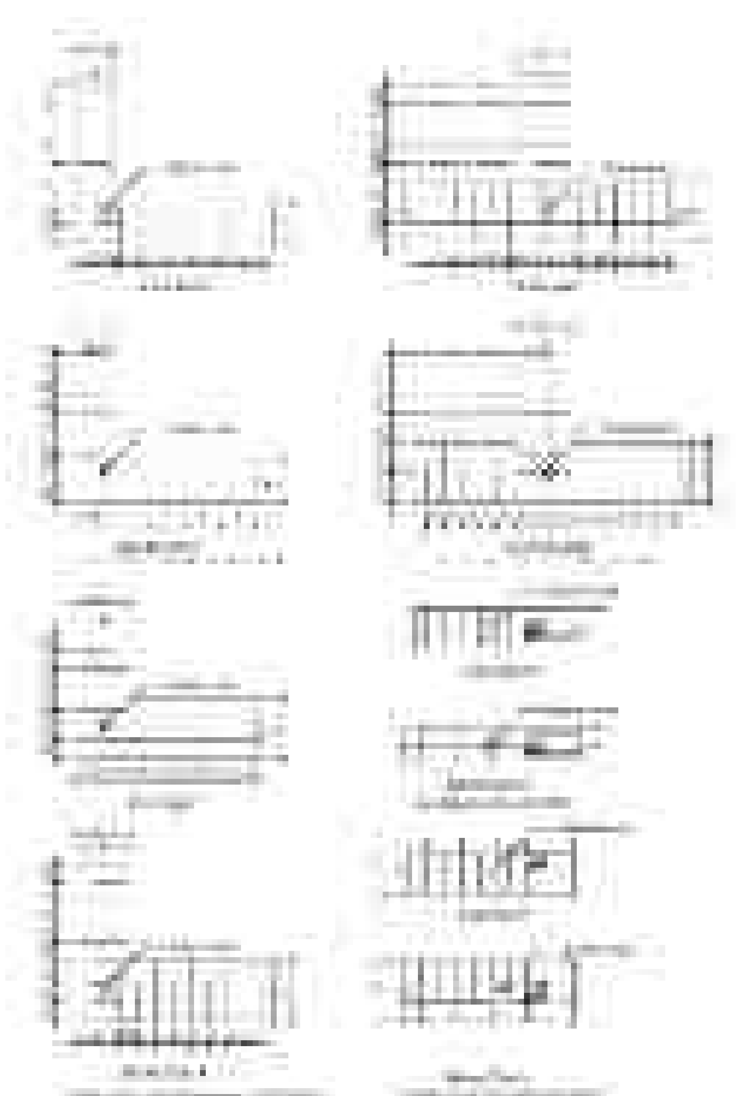
Figure 6.7.1 Typical details of vertical reinforcement in brick masonry
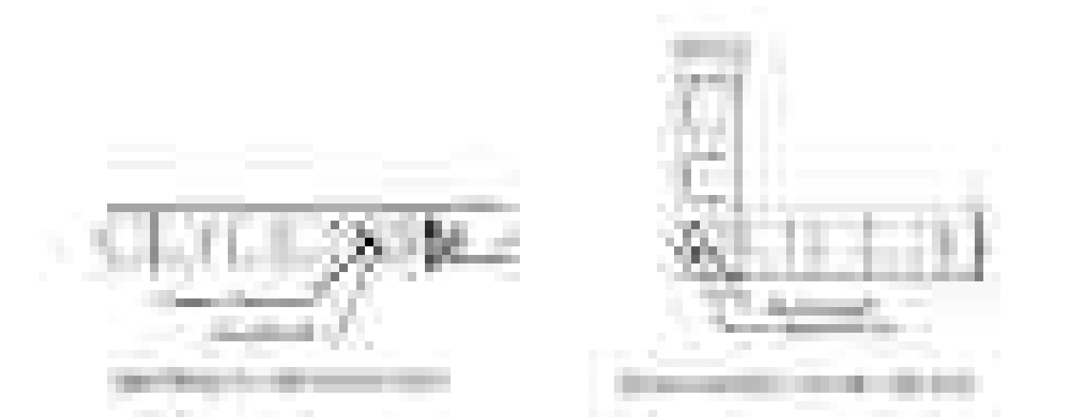
Figure 6.7.2 Typical details of vertical reinforcement in hollow block masonry
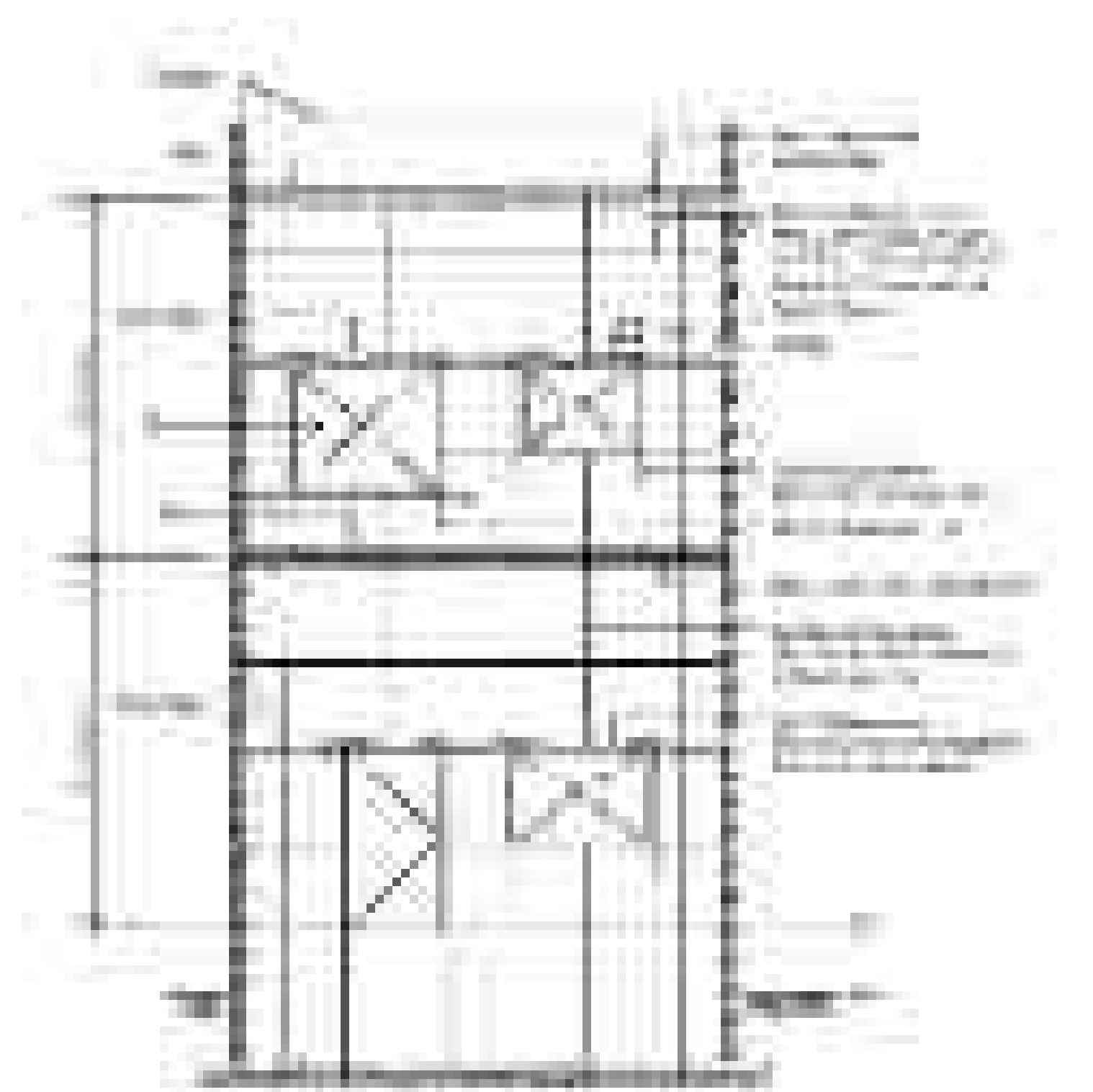
Figure 6.7.3 Minimum reinforcement in walls and around openings in Seismic Zones 2, 3 and 4
7.9 Provisions For High Wind Regions
7.9.1 General
The provisions of this Section shall apply to masonry structures located at regions where the basic wind speed is greater than 200 km/h.7.9.2 Materials
Materials for masonry structures shall generally comply with the provisions of Part 5; however, there are some special requirements for masonry construction in high wind regions, which are given below:- (a) Burnt clay bricks shall have a compressive strength not less than 15 N/mm² ,
- (b) Grout shall have a minimum compressive strength of 12.5 N/mm² ,
- (c)Mortar for exterior walls and interior shear walls shall be type M 1or M 2,
- (d) Unburnt clay masonry units shall not be used.
7.9.3 Construction Requirements
Masonry construction shall comply with the provisions of Sec 7.10.7.9.4 Foundation
Footings shall have a thickness of not less than 375 mm and shall be extended 450 mm below the undisturbed ground surface. Foundation stem wall shall have the same width and reinforcement as the wall it supports.7.9.5 Drainage
Walls retaining more than 1 m of earth and enclosing interior spaces or floors below grade shall have minimum 100 mm diameter footing drain. A slope of 1:50 away from the building shall be provided around the building.7.9.6 Wall Construction
7.9.6.1
Minimum thickness of different types of wall shall be as given in Table 6.7.18.7.9.6.2
All walls shall be laterally supported at the top and bottom. The maximum unsupported height of bearing walls or other masonry walls shall be 3.5 m. Gable end walls may be 4.5 m high at their peak.7.9.6.3
The span of lintels over openings shall not exceed 3.5 m. All lintels shall be reinforced and the reinforcement bars shall extend not less than 600 mm beyond the edge of opening and into lintel supports.7.9.6.4
Walls shall be adequately reinforced.7.9.6.5
Anchors between walls and floors or roofs shall be embedded in grouted cells or cavities and shall conform to Sec 7.9.7 below. Table 6.7.18: Minimum thickness of Walls in High Wind Region7.9.7 Floor and Roof Systems
Floors and roofs of all masonry structures shall be adequately anchored with the wall it supports to resist lateral and uplift forces due to wind specified in Sec 2.4 of this Part.7.9.8 Lateral Force Resistance
7.9.8.1
Strapping, approved framing anchors and mechanical fasteners, bond beams and vertical reinforcement shall be installed to provide a continuous tie from the roof to foundation system as shown in Figure 6.7.4. In addition, roof and floor systems, masonry shear walls, or masonry or wood cross walls shall be provided for lateral stability.7.9.8.2
Floor and roof diaphragms shall be properly connected to masonry walls. Gable and sloped roof members not supported at the ridge shall be tied by the ceiling joist or equivalent lateral ties located as close to where the roof members bear on the wall as practically possible and not at more than 1.2 m on centers. Collar ties shall not be used for these lateral ties.7.9.8.3
Masonry walls shall be provided around all sides of floor and roof systems in accordance with Figure 6.7.5. The cumulative length of exterior masonry walls along each side of the floor or roof systems shall be at least 20 percent of the parallel dimension. Required elements shall be without openings and shall not be less that 1.25 m in width. Interior cross walls at right angles to bearing walls shall be provided when the length of the building perpendicular to the span of the floor of roof framing exceeds twice the distance between shear walls or 10 m, whichever is greater.7.9.8.4
When required interior cross wall shall be at least 1.8 m long and reinforced with 2 mm wire joint reinforcement spaced not more than 400 mm on centre.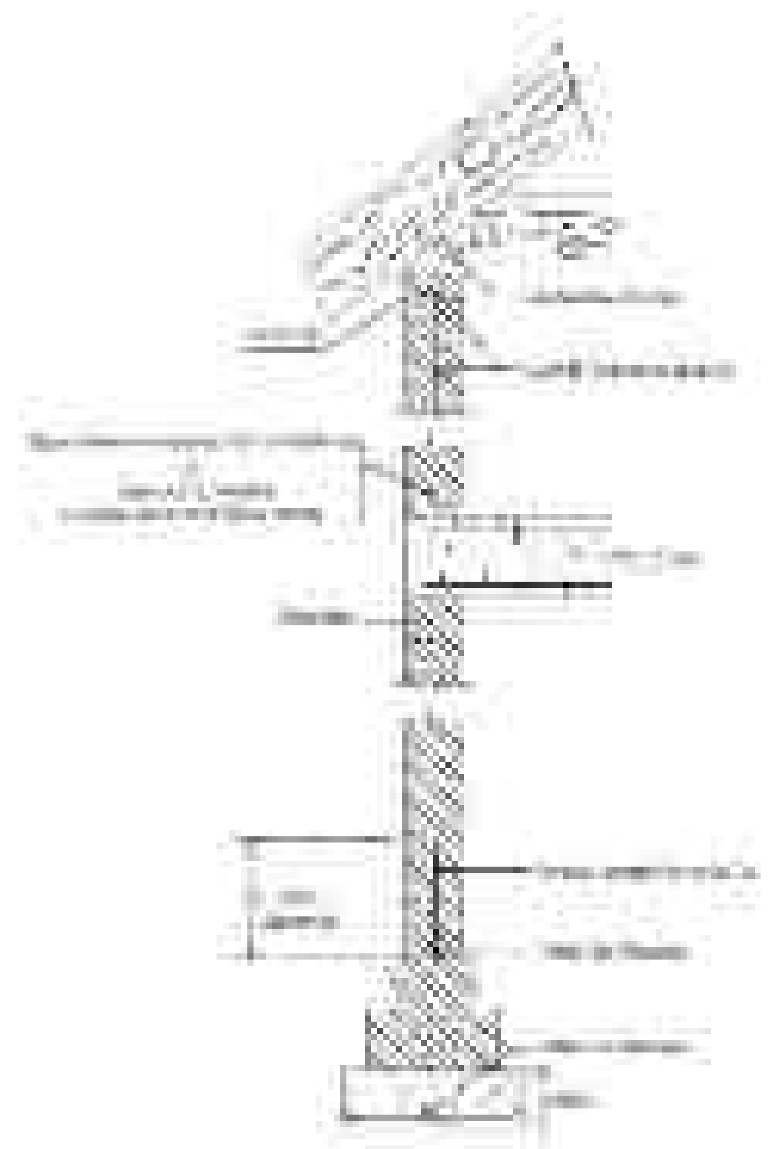
Figure 6.7.4 Continuous tie from roof to foundation of masonry structure
Figure 6.7.5 Masonry walls required in high wind regions
7.10 Construction
7.10.1 General
Masonry shall be constructed according to the provisions of this Section.7.10.2 Storage and Preparation of Construction Materials
Storage, handling and preparation at the site shall conform to the following:- (a) Masonry materials shall be stored in such a way that at the time of use the materials are clean and structurally suitable for the intended use.
- (b) All metal reinforcement shall be free from loose rust and other coatings that inhibit reinforcing bond.
- (c) Burnt clay units shall have a rate of absorption per minute not exceeding 1 litre/m2 at the time of lying. In the absorption test the surface of the unit shall be held 3 mm below the surface of the water.
- (d) Burnt clay units shall be thoroughly wetted before placing. Concrete masonry units shall not be wetted unless otherwise approved.
- (e) Materials shall be stored in such a manner that deterioration or intrusion of foreign materials is prevented and at the time of mixing the material conforms to the applicable requirements.
- (f) The method of measuring materials for mortar and grout shall be such that proportions of the materials can be easily controlled.
- (g) Mortar or grout mixed at the job site shall be mixed for a period of time not less than 3 minutes or more than 10 minutes in a mechanical mixer with the amount of water required to provide the desired workability. Hand mixing of small amounts of mortar is permitted. Mortar may be retempered. Mortar or grout which has hardened or stiffened due to hydration of the cement shall not be used, but under no case shall mortar be used two and one-half hours, nor grout used one and one-half hours, after the initial mixing water has been added to the dry ingredients at the job site.
7.10.3 Placing Masonry Units
- (a) The mortar shall be sufficiently plastic and units shall be placed with sufficient pressure to extrude mortar from the joint and produce a tight joint. Deep furrowing which produces voids shall not be used.
- (b) All surfaces in contact with mortar or grout shall be clean and free of deleterious materials.
- (c) Solid masonry units shall have full head and bed joints.
- (d) All head and bed joints shall be filled solidly with mortar for a distance from the face of the unit not less than the thickness of the shell. Head joints of open-end units with beveled ends need not be mortared. The beveled ends shall form a grout key which permits grout within 16 mm of the face of the unit. The units shall be tightly butted to prevent leakage of grout.
7.10.4 Verticality and Alignment
All masonry shall be built true and plumb within the tolerances prescribed below. Care shall be taken to keep the perpends properly aligned.- (a) Deviation from vertical within a storey shall not exceed 6 mm per 3m height.
- (b) Deviation in verticality in total height of any wall of a building more than one storey in height shall not exceed 12 mm.
- (c) Deviation from position shown on plan of any brickwork shall not exceed 12 mm.
- (d) Relative displacement between load bearing walls in adjacent storeys intended to be in vertical alignment shall not exceed 6 mm.
- (e) Deviation of bed joint from horizontal in a length of 12 m shall not exceed 6 mm subject to a maximum deviation of 12 mm.
- (f) Deviation from the specified thickness of bed joints, cross joints and perpends shall not exceed one-fifth of the specified thickness.
7.10.5 Reinforcement Placing
Reinforcing details shall conform to the requirements of Sec 7.6.6. Metal reinforcement shall be located in accordance with the plans and specifications. Reinforcement shall be secured against displacement prior to grouting by wire positioners or other suitable devices at intervals not exceeding 20 bar diameters. Tolerances for the placement of steel in walls and flexural elements shall be ±12 mm for 0 ≤200 mm, ±25 mm for 200 mm ≤0 ≤600 mm and ± 30 mm for 0 > 600 mm. Tolerance for longitudinal location of reinforcement shall be ± 50 mm.7.10.6 Grouted Masonry
Grouted masonry shall be constructed in such a manner that all elements act together as a structural element. Space to be filled with grout shall be clean and shall not contain any foreign materials. Grout materials and water content shall be controlled to provide adequate workability and shall be mixed thoroughly. The grouting of any section of wall shall be completed in one day with no interruptions greater than one hour. Size and height limitations of the grout space or cell shall not be less than those shown in Table 6.7.19. Higher grout pours or smaller cavity widths or cell size than shown in Table 6.7.19 may be used when approved, if it can be demonstrated that grout spaces are properly filled. Cleanouts are required for all grout pours over 1.5 m in height. When required, cleanouts shall be provided in the bottom course at every vertical bar but shall not be spaced more than 800 mm on centre for solidly grouted masonry. When cleanouts are required, they shall be sealed after inspection and before grouting. When cleanouts are not provided, special provisions must be made to keep the bottom and sides of the grout spaces, as well as the minimum total clear area as required by Table 6.7.19, clean and clear prior to grouting. Table 6.7.19: Grouting Limitations7.10.7 Chases, Recesses and Holes
- (a) Chases, recesses and holes may be permitted in masonry provided either they are considered in the structural design or they are not cut into walls made of hollow or perforated units, or vertical chases are planned instead of horizontal chases.
- (b) Depth of vertical and horizontal chases in load bearing walls shall not exceed one-third and one-sixth of the wall thickness respectively.
- (c) Vertical chases shall not be closer than 2 m in any stretch of wall and shall not be located within 350 mm of an opening or within 230 mm of a cross wall that serves as stiffening wall for stability. Width of a vertical chase shall not exceed the thickness of wall in which it occurs.
- (d) Horizontal chases shall be located in the upper or lower middle third height of wall at a distance not less than 600 mm from lateral support. No horizontal chase shall exceed one metre in length and there shall not be more than 2 chases in any one wall. Horizontal chases shall have minimum mutual separation distance of 500 mm. Sum of lengths of all chases and recesses in any horizontal plane shall not exceed one-fourth the length of the wall.
- (e) Lintel shall not be used to support masonry directly above a recess or a hole wider than 300 mm. No lintel however, is necessary in case of a circular recess or hole exceeding 300 mm in diameter provided upper half of the recess or hole is built as a semi-circular arch of adequate thickness and there is adequate length of masonry on the sides of openings to resist the horizontal thrust.
- (f) Recesses and holes in masonry shall be kept at the time of construction so as to avoid subsequent cutting. If cutting is necessary, it shall be done using sharp tools without causing heavy impact and damage to the surrounding areas.
- (g) No chase, recess or hole shall be provided in half-brick load bearing wall, excepting the minimum number of holes needed for scaffolding.
7.11 Confined Masonry
7.11.1 General
Confined masonry construction consists of masonry walls (made either of clay brick or concrete block units) and horizontal and vertical RC confining members built on all four sides of a masonry wall panel. Vertical members, called tiecolumns or practical columns, resemble columns in RC frame construction except that they tend to be of far smaller cross-section. Horizontal elements, called tie-beams, resemble beams in RC frame construction. To emphasize that confining elements are not beams and columns, alternative terms horizontal ties and vertical ties could be used instead of tie-beams and tie-columns. The confining members are effective in- (a) Enhancing the stability and integrity of masonry walls for in-plane and out-of-plane earthquake loads (confining members can effectively contain damaged masonry walls),
- (b) Enhancing the strength (resistance) of masonry walls under lateral earthquake loads, and
- (c) Reducing the brittleness of masonry walls under earthquake loads and hence improving their earthquake performance.
- (a) Masonry walls – transmit the gravity load from the slab(s) above down to the foundation. The walls act as bracing panels, which resist horizontal earthquake forces. The walls must be confined by concrete tie-beams and tie-columns to ensure satisfactory earthquake performance.
- (b) Confining elements (tie-columns and tie-beams) - provide restraint to masonry walls and protect them from complete disintegration even in major earthquakes.
- (a) Floor and roof slabs - transmit both gravity and lateral loads to the walls. In an earthquake, slabs behave like horizontal beams and are called diaphragms.
- (b) Plinth band - transmits the load from the walls down to the foundation. It also protects the ground floor walls from excessive settlement in soft soil conditions.
- (c) Foundation - transmits the loads from the structure to the ground.

Figure 6.7.6 Typical confined masonry building
7.11.2 Difference of Confined Masonry from RC Frame Construction
The appearance of a finished confined masonry construction and a RC frame construction with masonry in fills may look alike, however these two construction systems are substantially different. The main differences are related to the construction sequence, as well as to the manner in which these structures resist gravity and lateral loads. These differences are summarized in Table 6.7.20 and are illustrated by diagrams in Figure 6.7.7. In confined masonry construction, confining elements are not designed to act as a moment-resisting frame; as a result, detailing of reinforcement is simple. In general, confining elements have smaller cross-sectional dimensions than the corresponding beams and columns in a RC frame building. It should be noted that the most important difference between the confined masonry walls and infill walls is that infill walls are not load-bearing walls, while the walls in a confined masonry building are. A transition from RC frame to confined masonry construction in most cases leads to savings related to concrete cost, since confining elements are smaller in size than the corresponding RC frame members. Table 6.7.20: Comparison between confined masonry and RC frame construction7.11.3 Mechanism of Resisting Earthquake Effects
A confined masonry building subjected to earthquake ground shaking can be modeled as a vertical truss, as shown in Figure 6.7.8. Masonry walls act as diagonal struts subjected to compression, while reinforced concrete confining members act in tension and/or compression, depending on the direction of lateral earthquake forces. This model is appropriate before the cracking in the walls takes place. Subsequently, the cracking is concentrated at the ground floor level and significant lateral deformations take place. Under severe earthquake ground shaking, the collapse of confined masonry buildings may take place due to soft storey effect similar to the one observed in RC frames with masonry in fills, as shown in Figure 6.7.8. The following failure modes are characteristic of confined masonry walls: (a) Shear failure mode, and; (b) Flexural failure mode. Note that, in confined masonry structures, shear failure mode develops due to in-plane seismic loads (acting along in the plane of the wall), whereas flexural failure mode may develop either due to in-plane or out-of-plane loads (acting perpendicular to the wall plane). Shear failure mode is characterized by distributed diagonal cracking in the wall. These cracks propagate into the tie-columns at higher load levels, as shown in Figure 6.7.9. Initially, a masonry wall panel resists the effects of lateral earthquake loads by itself while the confining elements (tie-columns) do not play a significant role. However, once the cracking takes place, the wall pushes the tie-columns sideways. At that stage, vertical reinforcement in tie-columns becomes engaged in resisting tension and compression stresses. Damage in the tie-columns at the ultimate load level is concentrated at the top and the bottom of the panel. These locations, characterized by extensive crushing of concrete and yielding of steel reinforcement, are called plastic hinges (Figure 6.7.10). Note that the term plastic hinge has a different meaning in the context of confined masonry components than that referred to in relation to RC beams and columns, where these hinges form due to flexure and axial loads. In confined masonry construction, tie-beams and tie-columns resist axial loads. Shear failure can lead to severe damage in the masonry wall and the top and bottom of the tie-columns.
Figure 6.7.7 (a) RC frame construction; (b) Confined masonry construction
Figure 6.7.8 Confined masonry building: (a) Vertical truss model; (b) Collapse at the ground floor level
Figure 6.7.9 Shear failure of confined masonry walls
Figure 6.7.10 Plastic hinge developed in a confined masonry wall
7.11.4 Key Factors Influencing Seismic Resistance
7.11.4.1 Wall density
Wall density is believed to be one of the key parameters influencing the seismic performance of confined masonry buildings. It can be determined as the transverse area of walls in each principal direction divided by the total floor area of the building.7.11.4.2 Masonry units and mortar
The lateral load resistance of confined masonry walls strongly depends on the strength of the masonry units and the mortar used. The walls built using lowstrength bricks or ungrouted hollow block units had the lowest strength while the ones built using grouted or solid units had the largest strength. However, the use of grouted and solid units results in an increase both in wall mass and seismic loads. Also, the weaker the mortar the lower the masonry strength (due to the unit-mortar interaction, the masonry strength is always lower than the unit strength). There is no significant difference in strength between unreinforced and confined masonry wall specimens with the same geometry and material properties.7.11.4.3 Tie-columns
Tie-columns significantly influence the ductility and stability of cracked confined masonry walls. The provision of closely spaced transverse reinforcement (ties) at the top and bottom ends of tie-columns results in improved wall stability and ductility in the post-cracking stage.7.11.4.4 Horizontal wall reinforcement
Horizontal reinforcement has a beneficial effect on wall ductility. Specimens with horizontal reinforcement showed a more uniform distribution of inclined shear cracks than the unreinforced specimens. Horizontal rebars should be anchored into the tie-columns; the anchorage should be provided with 900 hooks at the far end of the tie-column (Figure 6.7.12). The hooks should be embedded in the concrete within the tie-column (note that the tie-column reinforcement was omitted from the figure). The bar diameter should be larger than 3.5 mm and less than ¾ the joint thickness.7.11.4.5 Openings
When the opening area is less than approximately 10 percent of the total wall area, the wall lateral load resistance is not significantly reduced as compared to a solid wall (i.e. wall without openings). The walls with larger openings develop diagonal cracks (same as solid walls), except that the cracks are formed in the piers between the openings; thus, diagonal struts form in the piers, as shown in Figure 6.7.13.7.11.5 Verification of Members
7.11.5.1
In the verification of confined masonry members subjected to bending and/or axial loading, the assumptions for reinforced masonry members should be adopted. In determining the design value of the moment of resistance of a section a rectangular stress distribution may be assumed, based on the strength of the masonry, only. Reinforcement in compression should also be ignored.7.11.5.2
In the verification of confined masonry members subjected to shear loading the shear resistance of the member should be taken as the sum of the shear resistance of the masonry and of the concrete of the confining elements. In calculating the shear resistance of the masonry the rules for unreinforced masonry walls subjected to shear loading should be used, considering the length of the masonry element. Reinforcement of confining elements should not be taken into account.7.11.5.3
In the verification of confined masonry members subjected to lateral loading, the assumptions set out for unreinforced and reinforced masonry walls should be used. The contribution of the reinforcement of the confining elements should be considered.
Figure 6.7.11 Flexural failure of confined masonry walls
Figure 6.7.12 Horizontal reinforcement in confined masonry walls
Figure 6.7.13 Failure modes in the confined masonry walls with openings
7.11.6 Confined Masonry Members
7.11.6.1
Confined masonry members shall not exhibit flexural cracking nor deflect excessively under serviceability loading conditions.7.11.6.2
The verification of confined masonry members at the serviceability limit states shall be based on the assumptions given for unreinforced masonry members.7.11.7 Architectural Guideline
7.11.7.1 Building Layout
- (a) The building should not be excessively long relative to its width; ideally, the length-to-width ratio should not exceed 4.
- (b) The walls should be continuous up the building height.
- (c) Openings (doors and windows) should be placed in the same position up the building height.
7.11.7.2 Walls
- (a) At least two fully confined walls should be provided in each direction.
- (b) For Seismic Zone 1 and 2, wall density of at least 2 percent in each of two orthogonal directions is required to ensure good earthquake performance of confined masonry construction. The wall density for Seismic Zones 3 and 4 should be at least 4 percent and 5 percent respectively. Wall density can be defined as the total cross sectional area of all walls in one direction divided by the sum of the floor plan areas for all floors in a building.
7.11.7.3 Building Height
Confined masonry is suitable for low- to medium-rise building construction. Confined masonry buildings will be subject to the following height restrictions:- (a) Up to 4-storey high for Seismic Zone 1 and 2
- (b) Up to 3-storey high for Seismic Zone 3
- (c) Up to 2-storey high for Seismic Zone 4
7.11.8 Confined Masonry Details
7.11.8.1
Confined masonry walls shall be provided with vertical and horizontal reinforced concrete or reinforced masonry confining elements so that they act together as a single structural member.7.11.8.2
Top and sides confining elements shall be cast after the masonry has been built so that they will be duly anchored together.7.11.8.3
Vertical confining elements should be placed:- (a) at the free edges of each structural wall element;
- (b) at both sides of any wall opening with an area of more than 1.5 m2 ;
- (c) within the wall if necessary in order not to exceed a spacing of 5 m between the confining elements;
- (d) at the intersections of structural walls, wherever the confining elements imposed by the above rules are at a distance larger than 1.5 m.
7.11.8.4
Horizontal confining elements shall be placed in the plane of the wall at every floor level and in any case with a vertical spacing of not more than 4 m.7.11.8.5
Confining elements should have a cross-sectional area not less than 0.02 m2 , with a minimum dimension of 150 mm in the plan of the wall. In double-leaf walls the thickness of confining elements should assure the connection of the two leaves and their effective confinement.7.11.8.6
The longitudinal reinforcement of confining elements may not have a cross-sectional area less than 300 mm2 , nor than 1 percent of the cross-sectional area of the confining element. The detailing of the reinforcements should be in accordance with Chapter 8.7.11.8.7
Stirrups not less than 6 mm in diameter and spaced not more than 300 mm should be provided around the longitudinal reinforcement. Column ties should preferably have 135° hooks – the use of 90° hooks is not recommended. At a minimum, 6 mm ties at 200 mm spacing (6 mm@200 mm) should be provided. It is recommended to use 6 mm ties at 100 mm spacing (6 mm@100 mm) in the column end-zones (top and bottom).7.11.8.8
To ensure the effectiveness of tie-beams in resisting earthquake loads, longitudinal bars should have a 90° hooked anchorage at intersections, as shown in Figure 6.7.14. The hook length should be at least 500 mm.7.11.8.9
Proper detailing of the tie-beam-to-tie-column connections is a must for satisfactory earthquake performance of the entire building. Reinforcing bars must be properly anchored. A typical connection detail at the roof level is shown in Figure 6.7.15. Note that the tie-column reinforcement needs to be extended into the tie-beam as much as possible, preferably up to the underside of the top tie-beam reinforcement. A hooked anchorage needs to be provided (90° hooks) both for the tie-column and tie-beam reinforcement.7.11.8.10
Special lintel beams may be required across larger openings having a width exceeding 1.5 m. Additional reinforcement bars need to be provided. Lintel beams can be integrated with the tie-beams at the floor level.7.11.8.11
Lap splices may not be less than 60 bar diameters or 500 mm in length. Splicing should take place at column mid height, except for the ground floor level (where splicing is not permitted).7.11.8.12
The minimum wall thickness should not be less than 100 mm. The wall height/thickness ratio should not exceed 30.7.11.8.13
Toothed edges should be left on each side of the wall, as shown in Figure 6.7.16(a). Toothed edges are essential for adequate wall confinement, which contributes to satisfactory earthquake performance. Alternatively, when the interface between the masonry wall and the concrete tie-column needs to remain smooth for appearance’s sake, steel dowels should be provided in mortar bed joints to ensure interaction between the masonry and the concrete during an earthquake, Figure 6.7.16(b).7.11.8.14
Concrete in the tie-columns can be poured once the desired wall height has been reached. The masonry walls provide formwork for the tiecolumns on two sides; however the formwork must be placed on the remaining two sides.7.11.9 Foundation and Plinth Construction
The foundation should be constructed as in traditional brick masonry construction. Either an uncoursed random rubble stone masonry footing or a RC strip footing can be used. A RC plinth band should be constructed on top of the foundation. In confined masonry construction, plinth band is essential for preventing building settlements in soft soil areas. An alternative foundation solution with RC strip footing is also illustrated in Figure 6.7.17.
Figure 6.7.14 Tie-beam construction: (a) Wall intersections; (b) Hooked anchorage to longitudinal reinforcement

Figure 6.7.15 Detailing requirement for the tie-beam-to-tie-column connection
Figure 6.7.16 (a) Toothed wall construction; (b) Horizontal dowels at the wall-to-column interface
Figure 6.7.17 Foundation construction: (a) RC plinth band and stone masonry foundation; (b) RC strip footing